
Related Manuals for Viessmann VITOCROSSAL CI


Summary of Contents for Viessmann VITOCROSSAL CI
- Page 1 VIESMANN Operating instructions for the system user Vitocrossal, type CI with Vitotronic 200 control unit, type GW7B, for weather-compensated operation VITOCROSSAL Please keep safe. 5814953 GB 1/2018...
- Page 2 Safety instructions For your safety Please follow these safety instructions closely to prevent accidents and material losses. Safety instructions explained Danger Note This symbol warns against the risk of injury. Details identified by the word "Note" contain additional information. Please note This symbol warns against the risk of material losses and environmental pollution.
-
Page 3: Safety Instructions
Safety instructions For your safety (cont.) If you smell gas Danger Escaping gas can lead to explosions which may result in serious injury. ■ Never smoke. Prevent naked flames and sparks. Never switch lights or electrical appli- ances on or off. Close the gas shut-off valve. - Page 4 Safety instructions For your safety (cont.) Installation room requirements Danger Please note Sealed vents result in a lack of combustion air. Incorrect ambient conditions can lead to heating This leads to incomplete combustion and the system damage and can put safe operation at formation of life threatening carbon monoxide.
- Page 5 Index Index 1. Information Symbols ....................Intended use ..................2. Introductory information Commissioning ..................Terminology ................... Your system is preset ................Tips on saving energy ................Tips for greater comfort ................. 3. Operation Opening the control unit ................. 10 Programming unit .................. 10 "Help"...
- Page 6 Index Index (cont.) Naming heating circuits ................. 26 Setting the preferred heating circuit for the standard menu ....27 Setting the time and date ............... 27 Setting the language ................27 Setting the temperature unit (°C/°F) ............27 Restoring factory settings ..............28 8.
-
Page 7: Intended Use
Information Symbols Symbol Meaning Reference to other document containing further information Step in a diagram: The numbers correspond to the order in which the steps are carried out. Warning of material losses and environ- mental pollution Live electrical area Pay particular attention. Component must audibly click into place. -
Page 8: Tips On Saving Energy
Introductory information Commissioning The commissioning and matching of the control unit to As the user of new combustion equipment, you may be local conditions and building characteristics, as well as obliged to notify your local flue gas inspector of the instructing the user in the operation of the system, installation [check local regulations]. -
Page 9: Introductory Information
Introductory information Tips on saving energy (cont.) ■ Holidays (see page 22): DHW heating If you are going away, select the "Holiday pro- gram": DHW circulation pump (see page 25): ■ The room temperature is reduced and DHW heating Only activate the DHW circulation pump for periods is turned off. -
Page 10: Programming Unit
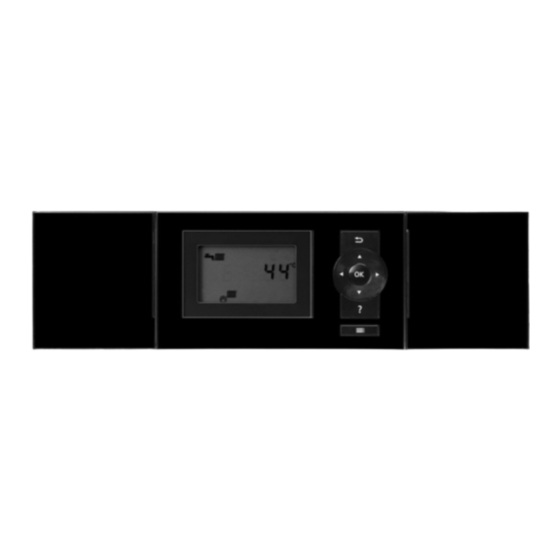
Operation Opening the control unit 21°C 14°C Fig. 1 Programming unit You can change any setting on your heating system Note centrally at the programming unit of the control unit. The programming unit can be placed in a wall mount- If remote control units are installed in your rooms, you ing base. -
Page 11: Operation
Operation Programming unit (cont.) Symbols These symbols are not always displayed, but appear Burner in operation subject to the system version and the operating condi- Emissions test mode active tion. Heating circuits: Displays: HC... Heating circuit ... Frost protection is active. Central heating to standard room temperature Operating programs: Central heating with reduced room temperature... -
Page 12: Extended Menu
Operation Standard menu (cont.) Setting the operating program for the preferred heating circuit Press the following keys: for the required operating program Extended menu In the extended menu, you can call up and adjust all Note the settings from the Vitotronic control unit range of Your heating contractor can block operation for the functions, e.g. - Page 13 Operation How to use the controls (cont.) 1. Press OK. This takes you to the standard menu Adjustments to the central heating can be made for (see page 11). every heating circuit. It is therefore necessary to select the required heating circuit prior to making any adjust- 2.
-
Page 14: Time Program
Operation Operating program Operating programs for central heating, DHW, frost protection Symbol Operating program Function Central heating and DHW heating "Heating and DHW" The rooms of the selected heating circuit are ■ heated in accordance with the room temperature and time program specified (see chapter "Central heating"). - Page 15 Operation Time program (cont.) ■ For each time phase you set the start and end points. The selected time phase is illustrated by a white bar on the time chart. ■ In the extended menu, you can call up the time pro- grams under "Information"...
- Page 16 Operation Time program (cont.) Example: You want to set a different time program for Monday: 1. Select "Monday-Sunday". Set the time program. Heating time program Note Monday-Sunday The tick is always set at the sections of the week ê ç with identical time phases.
-
Page 17: Switching On The Heating System
Start-up/shutdown Switching on the heating system 21°C 14°C Kesseltemperatur 48°C Fig. 12 Fault indicator (red) Reset button ON indicator (green) ON/OFF switch Ask your heating contractor about the following: 3. Open the gas shut-off valve. ■ Level of the required system pressure Position of the following components: 4. - Page 18 Start-up/shutdown Shutting down the heating system (cont.) For the preferred heating circuit For all heating circuits Standard menu Extended menu 1. / for the operating program "Standby mode" (frost protection monitoring). 2. "Heating" 2. OK 3. / for the required heating circuit if necessary 4.
-
Page 19: Room Temperature
Central heating Room temperature Further information can be found in chapter "Terminology" in the appendix. Setting the standard room temperature Factory setting: 20 °C For the preferred heating circuit For all heating circuits Standard menu Extended menu 1. / for the required value 2. -
Page 20: Heating Curve
Central heating Time program (cont.) Setting the time program for central heating Factory setting: One time phase from 06:00 to 22:00 h Note for every day of the week When adjusting the setting, bear in mind that your heating system requires some time to heat the rooms Extended menu: to the required temperature. -
Page 21: Boiler Temperature
Central heating Comfort function "Party mode" Setting "Party mode" Extended menu Display in the standard menu 2. "Heating" 3. / for the required heating circuit if necessary 4. "Party mode" 5. Set the required room temperature for "Party mode". 21°C 14°C Party mode Boiler temperature... -
Page 22: Holiday Program
Central heating Energy saving function "Economy mode" (cont.) Display in the standard menu Note The display of the set room temperature does not change. 21°C 14°C Boiler temperature 48°C Fig. 16 Terminating "Economy mode" Ends automatically when the system switches to ■... - Page 23 Central heating "Holiday program" energy saving function (cont.) Display in the extended menu In the extended menu, you can call up the set holiday program under "Information" (see page 38). Cancelling or deleting the "Holiday program" Extended menu 3. "Holiday program" 4.
-
Page 24: Dhw Temperature
DHW heating DHW temperature Factory setting: 50 °C 3. "Set DHW temperature" 4. Set the required value. Extended menu 2. "DHW" Heating program Further information can be found in chapter "Terminology" in the appendix. Setting the operating program for DHW heating For the preferred heating circuit For all heating circuits Standard menu... -
Page 25: Switching Off Dhw Heating
DHW heating Time program (cont.) DHW heating once, outside the time program Note 3. "Party mode" The "Heating and DHW" or "Only DHW" operating 4. Confirm the party temperature with "OK". program must be set for at least one system heating 5. -
Page 26: Setting The Display Brightness
Further adjustments Setting the display contrast You can make the menu texts easier to read. To do so, 2. "Settings" adjust the contrast of the display to suit the lighting conditions in the room. 3. "Contrast" 1. Extended menu: 4. Set the required contrast. Setting the display brightness You would like to be able to read the text in the menu 2. -
Page 27: Setting The Language
Further adjustments Naming heating circuits (cont.) The menu shows "Apartment" for "Heating circuit 2". Apartment Ù Ú Party mode 22°C Economy mode ß Set room temperature Set reduced room temp Select with Fig. 21 Setting the preferred heating circuit for the standard menu If your heating system has several heating circuits, Extended menu you can select the heating circuit to be displayed in the... -
Page 28: Restoring Factory Settings
Further adjustments Setting the temperature unit (°C/°F) (cont.) 2. "Settings" 4. Select the temperature unit "°C" or "°F". 3. "Temperature unit" Restoring factory settings You can reset the factory settings of all modified values 3. "Standard setting" for each heating circuit separately. 4. -
Page 29: Scanning Information
Calling up information Scanning information Subject to the components connected and the settings Solar energy made, you can scan current temperatures and operat- ing conditions. In the extended menu, information is split into groups: ■ "General" ■ "Heating circuit 1" Su Mo ■... - Page 30 Calling up information Scanning service messages (cont.) 1. You can call up the reason for the service with OK. Note If the service cannot be carried out until a later date, Service the service message will be displayed again the follow- ing Monday.
-
Page 31: Scanning Fault Messages
Calling up information Scanning fault messages If any faults have occurred in your heating system, the 3. Make a note of the cause of the fault and the fault symbol flashes on the display and "Fault" is shown. code next to it on the right. In the example: "Out- The red fault indicator flashes (see chapter "Starting side t sens 18"... -
Page 32: Test Mode
Emissions test mode Emissions test mode Emissions test mode for testing flue gas with briefly Note raised boiler water temperature. The flue gas inspector can also activate emissions test Emissions test mode should only be activated by your mode if the controls have been locked by your heating flue gas inspector during the annual inspection. -
Page 33: Rooms Are Too Cold
What to do if... Rooms are too cold Cause Remedy The heating system is switched off. Turn on the ON/OFF switch (see diagrams from ■ page 17). Switch ON the mains isolator if installed (outside the ■ boiler room). Set the MCB in the power distribution board (main do- ■... -
Page 34: Rooms Are Too Hot
What to do if... Rooms are too hot Cause Remedy Control unit incorrectly adjusted. Check the settings and correct if required: ■ The remote control (if installed) is set incorrectly. Operating program (see page 19) ■ ■ Separate operating instructions Room temperature (see page 19) ■... -
Page 35: Ã Flashes And "Fault" Is Displayed
What to do if... flashes and "Fault" is displayed ã Cause Remedy Heating system fault Proceed as described on page 31. flashes and "Service" is displayed ë Cause Remedy The time for a service, as specified by your heating Proceed as described on page 29. contractor, has arrived. -
Page 36: Inspection And Maintenance
Maintenance Cleaning All equipment can be cleaned with a commercially available domestic cleaning agent (non-scouring). Clean the surface of the programming unit with the microfibre cloth provided. Inspection and maintenance The inspection and maintenance of a heating system Regular maintenance ensures trouble-free, energy effi- is prescribed by the Energy Saving Ordinance [EnEV - cient, environmentally responsible and safe heating. -
Page 37: Damaged Cables / Lines
If there is damage to the connecting cables or lines of the appliance or externally installed accessories, these must be replaced with special cables or lines. Only use Viessmann cables / lines as replacement. For this, notify your qualified contractor. - Page 38 Appendix Overview of extended menu Fig. 32 Scanning options under "Information" Note "Hours run" Subject to the features of your heating system, not all "Burner stage 1" of the information listed here may be available to call "Hours run" You can call up more details where information is "Burner stage 2"...
- Page 39 Appendix Scanning options under "Information" (cont.) "Wireless remote control" "Time program" "Time" "Set room temperature" "Date" "Room temperature" "Radio clock signal" "Set reduced room temp" "Set ext. room temp" Heating circuit 1 (HC1) "Set party temp" "Operating program" "Slope" "External hook-up" ■...
- Page 40 Appendix Terminology (cont.) Operating program Heating mode You define the following with the operating program: Standard heating mode Central heating and DHW heating ■ For periods when you will be at home during the day, ■ DHW heating only, no central heating heat your rooms to the standard room temperature.
- Page 41 Appendix Terminology (cont.) Slope Outside temperature in °C Fig. 33 Example: Heating circuit pump For outside temperature 14 °C: − Underfloor heating system, slope 0.2 to 0.8 Circulation pump for circulating the heating water in Low temperature heating system, slope 0.8 to 1.6 the heating circuit Heating system with a boiler water temperature in Mixer...
- Page 42 Appendix Terminology (cont.) Safety valve Safety equipment that must be installed in the cold water pipe by your heating contractor. The safety valve opens automatically to prevent excess pressure in the DHW cylinder. Solar circuit pump In conjunction with solar thermal systems. The solar circuit pump delivers the cooled heat transfer medium from the indirect coil of the DHW cylinder to the solar collectors.
- Page 43 Keyword index Keyword index Energy saving function Actual temperature scanning........29 – Economy mode, central heating......21 Appliance start-up............17 – Holiday program............22 Extended menu............12 Extension kit...............40 Brightness, setting............26 External hook-up............14 External program............14 Central heating – Factory setting............8 Factory setting..............8 –...
- Page 44 Keyword index Keyword index (cont.) Room sealed operation..........41 Language setting............27 Room temperature Level of heating curve.......... 20, 40 – Energy saving............8 – For reduced heating mode........19 – Preferred heating circuit.......... 11 Maintenance...............36 – Reduced..............19 Maintenance contract..........36 – Standard..............19 Menu –...
- Page 45 Keyword index Keyword index (cont.) Temperature Underfloor heating............40 – Scanning..............29 – Setting..............19 – Standard room temperature........11 Water too cold............34 Temperature unit............27 Water too hot..............34 Terminology..............39 Weather-compensated mode........42 Test mode..............32 Window ventilation............9 Time, setting...............27 Winter mode...............40 Time/date, factory setting..........
-
Page 48: Your Contact
Your contact Contact your local contractor if you have any questions about your system or wish to arrange maintenance or repair work. You can find local contractors on the internet at www.viessmann.de. Viessmann Werke GmbH & Co. KG Viessmann Limited...
Need help?
Do you have a question about the VITOCROSSAL CI and is the answer not in the manual?
Questions and answers