
Related Manuals for BERMAD BIC-F


Summary of Contents for BERMAD BIC-F
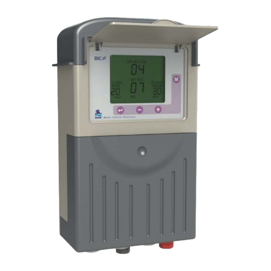
- Page 1 BIC-F Modular Backflushing Controller BERMAD Irrigation Control System DP ACTUAL BIC-F DP SET FLUSH FLUSH TIME MODE Operation Manual...
-
Page 2: Table Of Contents
BERMAD Operation Manual Controllers Contents Page Features and Benefits Program the Controller Description of Editable Fields Configuration Process Handling Endless Looping Problems Handling Low Pressure Connecting the DP Sensor to the Filter System Low Battery Manual Activation Timing Diagram Wiring Diagram... -
Page 3: Features And Benefits
Manage Pressure Sustaining or Main Valve – » Conserve energy by holding back pressure only during flush » Allows full flow when irrigating » Use BERMAD model x30-59 • Alarm output – » Alert locally or remote of filter system problems •... -
Page 4: Program The Controller
BERMAD Operation Manual Controllers 2. Program the Controller The controller is equipped with an LCD display and 4 keys (see image below). When the unit is left untouched for one minute the display switches off and the unit beeps every 20 seconds to indicate that the controller is still operating. -
Page 5: Description Of Editable Fields
BERMAD Operation Manual Controllers 3. Description of Editable Fields This section describes the options for each editable field. The image below illustrates the order in which the fields are activated when scrolling through them with the ENTER button. NOTE: The DP SET PoINT field is only enabled when the built-in electronic DP is used. -
Page 6: Configuration Process
BERMAD Operation Manual Controllers Flush Mode Defines how the flushing cycles are triggered. Select one of the following options: • OFF – no flushing occurs. • Time – flushing cycles are repeated in a defined interval or are triggered by the DP signal - whichever happens first. -
Page 7: Handling Endless Looping Problems
BERMAD Operation Manual Controllers its allocated function appears in large letters in the center of the screen. Notice that the number of possible outputs that can be used is always an even number since it results from the number of plug-in boards included (each board with 2 outputs) . -
Page 8: Handling Low Pressure
A small 120 mesh filter must be installed between the red fitting and the high pressure connection point (see image below). This filter is not supplied by Bermad and must be provided by the user. 120 mesh filter Filter Station Main irrigation line 8. -
Page 9: Timing Diagram
BERMAD Operation Manual Controllers 10. Timing Diagram Without Delay Valve Main valve Flush time Dwell Valve 1 Dwell time Valve 2 Valve 3 Valve 4 Including Delay Valve Main valve Dwell Valve 1 Dwell time Valve 2 Valve 3 Valve 4... -
Page 10: Wiring Diagram
BERMAD Operation Manual Controllers 11. Wiring Diagram DC MoDEL The image below shows the wiring of the DC model controller. Notice that: • The external DP sensor is optional and it is intended for use when there is no Embedded Electronic DP included. - Page 11 BERMAD Operation Manual Controllers AC MoDEL The drawing below shows the wiring of the AC model controller. Notice that: • The External DP sensor is optional and it is intended for use when there is no Embedded Electronic DP included.
-
Page 12: Technical Data
BERMAD Operation Manual Controllers 12. TECHNICAL DATA DC MoDEL • Power source - one of the following: » 6V supplied by 4 x 1.5 “D” size alkaline batteries » 12V DC dry battery » 12V rechargeable battery with solar panel of 2 watts •... - Page 13 BERMAD Water Control Solutions info@bermad.com • www.bermad.com © Copyright 2007-2012 Bermad CS Ltd. All Rights Reserved. The information contained in this document is subject to change without notice. BERMAD shall not be liable for any errors contained herein. May 2016...
Need help?
Do you have a question about the BIC-F and is the answer not in the manual?
Questions and answers