Table of Contents
Advertisement
Quick Links
Advertisement
Table of Contents

Related Manuals for metso automation maxPAC

Summary of Contents for metso automation maxPAC
- Page 1 Hardware Reference Guide 277596 Rev. C1...
- Page 2 Metso Automation MAX Controls, Inc. 1180 Church Road Lansdale, PA 19446 Attention: Manager, Technical Publications Copyright 2000-2002 by Metso Automation MAX Controls Inc. Printed in the United States of America All rights reserved Metso Automation MAX Controls Inc. • 277596 •...
-
Page 3: Table Of Contents
Redundant Configuration ..........................1-15 Mixed Configuration............................1-15 Remote I/O................................1-16 Specifications...............................1-18 Environment..............................1-18 I/O Bus................................1-18 Inputs/Outputs..............................1-18 CHAPTER 2 ........................2-1 Analog Input Modules Isolated Input Module IOP301 ................... 2-1 Overview..................................2-1 LED Indication ..............................2-1 Bus Address ................................2-2 Metso Automation MAX Controls Inc. • 277596 •... - Page 4 Module Operation ..............................5-2 Diagnostics................................5-3 Module Specifications............................5-4 Field Wiring ................................5-5 Field Wiring For Redundant Modules with Common TC..................5-6 CHAPTER 6........................6-1 Analog Output Modules 4-20 mA Output Module IOP320 ..................6-1 Metso Automation MAX Controls Inc. • 277596 •...
- Page 5 Contents LED Indication ..............................6-1 Bus Address ................................6-2 Jumper Configuration ............................6-2 Module Operation ..............................6-3 Diagnostics................................6-4 Module Specifications ............................6-5 Field Wiring................................6-6 Field wiring for redundant modules with common end element ................6-7 CHAPTER 7 ........................7-1 Digital Input Modules 24V Common Input Module IOP330 48V Common Input Module IOP331 ....7-1 Overview..................................7-1 LED Indication ..............................7-1 Bus Address ................................7-2...
- Page 6 Jumper Configuration............................11-2 DPU Compatibility............................11-4 I/O Bus Loading.............................. 11-4 BEM Operation..............................11-5 Optical Cabling ............................... 11-7 Model 564 and maxPAC I/O Compatibility....................11-7 Termination Requirements ..........................11-7 Redundant Configuration Approaches ........................ 11-7 Four Configuration Approaches........................11-7 Configuring Remote I/O only.......................... 11-8 Configuring Local Common I/O ........................
-
Page 7: Preface
Preface This publication, which describes the installation and operation of maxPAC, assumes familiarity with the DPU and its configuration. For additional information on related topics, refer to the following publications: Book No. Book Title 277522 Model PDP DPU Preparation and Adjustment... -
Page 8: Chapter 1
Input/Output Subsystem Overview The maxPAC Input/Output System links the maxDNA Distributed Control System to real world process control inputs and outputs. The Input/Output system uses a compact design to provide the system with greatly enhanced I/O capacity in relatively little space. A close relationship exists, in turn, between this I/O system and the maxDNA Distributed Processing Unit (DPU) which it serves. -
Page 9: Chassis Assembly
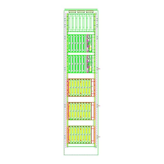
IOP383 Six-pack assembly to accommodate a DPU or a Model 564 I/O module in the right most position along with six maxPAC I/O modules; the DPU takes up the equivalent of two maxPAC I/O module positions. IOP381 Four-pack assembly to accommodate four maxPAC or Model 564 I/O modules. - Page 10 I/O bus to the maximum number of modules supported by the DPU. System 24V I/O Bus I/O Bus Connector Connectors Field 48V Field 24V Figure 1-2. Eight-Pack Rack Figure 1-3. Six Wide Rack with DPU Metso Automation MAX Controls Inc. • 277596 •...
-
Page 11: Dpu Mounting
The TC module includes front-end connectors with thermistors to measure the junction temperature for cold junction compensation. The I/O modules may be inserted and withdrawn safely with 24 Vdc and field power applied. Metso Automation MAX Controls Inc. • 277596 •... -
Page 12: I/O Module Types
48 Vdc common input; 16 channels IOP332 120 Vac/dc isolated input; 16 channels IOP333 240 Vac/Vdc isolated input; 16 channels IOP350 Form C relay; 10 channels IOP351 Form A/B relay; 16 channels *ac Voltages/currents are RMS Metso Automation MAX Controls Inc. • 277596 •... -
Page 13: Power Supply
I/O. This Power Supply Assembly consists of a 19-inch rack mount or flush mount chassis accommodating up to six independent 10 amp power supply modules. Metso Automation MAX Controls typically installs the power supply modules in an N + 1 redundancy configuration. Because each module is individually isolated, the chassis can be split to provide both system power and loop power. -
Page 14: Field Termination Options
Input/Output Subsystem Field Termination Options A maxPAC system uses two field cable termination approaches: Local Terminations Field cables terminate directly on the I/O module. Remote Terminations Field cables terminate on terminal blocks remotely module with interconnecting cable back to the I/O module. -
Page 15: Sequence Of Mounting Operations
Model IOP chassis assembly. 2. The holes in the maxDNA cabinet rear mounting rails are arranged in a repeating pattern of two holes close together separated by a single hole. Metso Automation MAX Controls Inc. • 277596 •... -
Page 16: Cabling, Power, And Ground Wiring
The I/O system requires a 24 Vdc ±4.0 Vdc power supply. Normally, this is a maxDNA power supply mounted in the cabinet holding the DPU; to ensure reliability, Metso Automation MAX Controls recommends using a maxDNA power supply exclusively. If another 24 Vdc power supply is used, it must meet the same specification requirements as the maxDNA supply. -
Page 17: Interconnecting Adjacent I/O Chassis
(CPO307), a 15-foot cable (CPO315), or a special length cable. The maximum number of modules supported by the DPU4E within a cabinet or cabinet pairs is 60 maxPAC modules. This number of modules is reduced when the I/O bus is extended to other cabinets. A bus terminator (CPO402) must be installed at the end of the I/O bus connection. -
Page 18: Module Mounting Considerations
I/O bus cable. Additionally, connect the cabinet frame ground to the Model IOP I/O chassis assembly before installing an I/O module in the extreme left position of a chassis assembly. Refer to "Cabling, Power, and Ground Wiring." Metso Automation MAX Controls Inc. • 277596 • 1-11... -
Page 19: Module Addressing
The lower switch is the low order address and the upper switch is the high order address. maxPAC modules use one, two or eight addresses. The address set on the module is its base address. For the eight-address module the base address is the address of channel 1. -
Page 20: Backup Configuration Options
Model IOP parallel modules. See Figure 1-6. Both DPUs share the I/O bus but only the active DPU (primary or secondary) receives data from, and sends data to, the set of common I/O modules. Redundant network I/O Bus Figure 1-6. Shared Configuration Metso Automation MAX Controls Inc. • 277596 • 1-13... -
Page 21: Redundant Configuration
In redundant or mixed configurations, the inactive DPU polls its redundant modules for hardware failures when it is not performing control actions. No transfer of control will occur if a failure is detected by the inactive DPU. The Metso Automation MAX Controls Inc. • 277596 • 1-14... -
Page 22: Remote I/O
DPU pair, and a BEM pair. This is connected via I/O optical cable to a ruggedized remote cabinet containing I/O modules, and a second BEM pair. The optical link is established between the local and remote Metso Automation MAX Controls Inc. • 277596 • 1-15... - Page 23 Any DPU or redundant pair of DPUs, can communicate with I/O that are locally and/or remotely mounted. See Figure 1-9. redundant network ADAPTER Control Room backplane backplane Optical Cable Remote location Figure 1-9. Typical Bus Expander Module Configuration Metso Automation MAX Controls Inc. • 277596 • 1-16...
-
Page 24: Specifications
Each output also has a deadman timer (approximately 1 second) that can be optionally used to freeze or drop out all outputs if the module is not updated by the DPU. Metso Automation MAX Controls Inc. • 277596 • 1-17... -
Page 25: Chapter 2
IOP302 input module. LED Indication A green LED, labeled Active at the bottom of the module front panel, is on when system power is present and the module is communicating with the Metso Automation MAX Controls Inc. • 277596 •... -
Page 26: Bus Address
These resistors can be used to scale a voltage input to the 2.4V span of the A/D measurement. These resistors are identified as follows: Channel Series R Shunt R Metso Automation MAX Controls Inc. • 277596 •... - Page 27 Rs = 0. 24V(+) From backplane 24V(-) Xmitter 4-20 ma powered by system Voltage Voltage input Xmitter 4-20 ma powered externally, internal shunt Metso Automation MAX Controls Inc. • 277596 •...
-
Page 28: Module Operation
I/O bus interface logic; its program is loaded from the FLASH on power up. Module calibration is done automatically at power up following startup diagnostics. Calibration is repeated periodically online to compensate for temperature effects. Metso Automation MAX Controls Inc. • 277596 •... -
Page 29: Diagnostics
Error Condition Code A/D send fault 0x12 A/D receive fault 0x13 A/D self calibration failure 0x14 Bad A/D communication 0x15 A/D does not complete conversion 0x16 RAM Test Failure (power-on) 0x22 Metso Automation MAX Controls Inc. • 277596 •... -
Page 30: Module Specifications
500 Volts ac or peak ac Common Mode Rejection 120db @ 50/60 Hz, 100 Ohm imbalance Isolation 1500 Vac (field to logic) 500 Vac (channel to channel) Input Power 400 mA (from 24V system supply) Metso Automation MAX Controls Inc. • 277596 •... -
Page 31: Field Wiring
24V,In(-) 24V,In(-) Channel 5 Channel 13 In(+) In(+) 24V,In(-) 24V,In(-) Channel 6 Channel 14 In(+) In(+) 24V,In(-) 24V,In(-) Channel 7 Channel 15 In(+) In(+) 24V,In(-) 24V,In(-) Channel 8 Channel 16 In(+) In(+) Metso Automation MAX Controls Inc. • 277596 •... -
Page 32: Field Wiring For Redundant Modules With Common Transmitter
250 Ohms. Kit IOP306 supplies 16 pairs of 100-Ohm shunts and thermistors to support two IOP301 analog input modules. pair Twisted 4 wire Transmitter thermistor Primary IOP301 AI Module Secondary IOP301 AI Module Four Wire Transmitter Metso Automation MAX Controls Inc. • 277596 •... - Page 33 Analog Input Modules Isolated Input Module IOP301 pair Twisted Supply thermistor Primary IOP301 AI Module 2 wire Transmitter Secondary IOP301 AI Module Two Wire Transmitter Metso Automation MAX Controls Inc. • 277596 •...
-
Page 34: Chapter 3
24V transmitter power for each channel. LED Indication A green LED, labeled Active at the bottom of the module front panel, is on when system power is present and the module is communicating with the Metso Automation MAX Controls Inc. • 277596 •... -
Page 35: Bus Address
FPGA. The FPGA provides the I/O bus interface logic; its program is loaded from the FLASH on power up. Module calibration is done automatically at power up following startup diagnostics. Calibration is repeated periodically online to compensate for temperature effects. Metso Automation MAX Controls Inc. • 277596 •... - Page 36 100 Volts. The 24-volt supply is available to the module from the backplane. Current Limit 24V(-) From backplane 24V(+) Fuse The following sketch shows the input circuit for the voltage-input module. Metso Automation MAX Controls Inc. • 277596 •...
-
Page 37: Diagnostics
Input Impedance IOP302, 300 Ohms; IOP305, 1mOhm Normal Mode Voltage IOP302, 50 Volts; IOP305, 24 Volts Normal Mode Rejection 60db @ 50/60 Hz Input Power 125 mA (from 24V system supply) Metso Automation MAX Controls Inc. • 277596 •... -
Page 38: Field Wiring For Iop302
Channel 11 Channel 4 Channel 12 Transmitter Transmitter Channel 5 Transmitter Transmitter Channel 13 Channel 6 Transmitter Transmitter Channel 14 Transmitter Transmitter Channel 7 Channel 15 Transmitter Channel 8 Transmitter Channel 16 Metso Automation MAX Controls Inc. • 277596 •... -
Page 39: Field Wiring - Iop 305 Analog Input Module
Channel 3 Channel 12 Channel 4 0-2.4V 0-2.4V Channel 13 Channel 5 0-2.4V 0-2.4V Channel 14 Channel 6 0-2.4V 0-2.4V Channel 15 0-2.4V Channel 7 0-2.4V Channel 16 Channel 8 0-2.4V 0-2.4V Metso Automation MAX Controls Inc. • 277596 •... -
Page 40: Field Wiring For Redundant Modules With Common Transmitter
Ohms. Kit IOP306 supplies 16 pairs of 100-Ohm shunts and thermistors to support two IOP305 analog input modules. DCS 24V Loop Supply pair Twisted Transmitter 2-wire thermistor Primary IOP305 AI Module Secondary IOP 305 AI Module Metso Automation MAX Controls Inc. • 277596 •... -
Page 41: Chapter 4
DPU. This LED blinks on and off when the module is not being scanned by the DPU. It is also used to display errors detected by diagnostics. Metso Automation MAX Controls Inc. • 277596 •... -
Page 42: Bus Address
A/D is serial at 100kHz. Optical isolators provide the isolation between the A/D and the serial logic circuits. The microprocessor provides the input data to the DPU on demand Metso Automation MAX Controls Inc. • 277596 •... - Page 43 Calibration is repeated periodically online to compensate for temperature effects. 5V - logic Regulator DC/DC 5V - field Excitation FLASH Current Channel 1 Field OPTO Field Interface Interface I/O Bus Circuits Circuits Channel 8 optical isolation field to logic Metso Automation MAX Controls Inc. • 277596 •...
-
Page 44: Diagnostics
Normal Mode Rejection 60db @ 50/60 Hz Common Mode Rejection 120db @ 50/60Hz, 100 Ohm imbalance Common Mode Voltage 240V rms, 350V dc peak Input Power 125 mA (from 24V system supply) Metso Automation MAX Controls Inc. • 277596 •... -
Page 45: Field Wiring
Analog Input Modules 3-Wire RTD Module IOP 303 Field Wiring Channel 1 Channel5 Channel 2 Channel 6 Channel 3 Channel 7 Channel 4 Channel 8 Note: Field wires must be of equal length Metso Automation MAX Controls Inc. • 277596 •... -
Page 46: Field Wiring For Redundant Modules With Common Rtd
Hardware Reference Guide Field Wiring For Redundant Modules with Common RTD pair, same length Twisted Primary IOP303 RTD Module W2 – not installed Secondary IOP 303 RTD Module W2 - not installed Metso Automation MAX Controls Inc. • 277596 •... -
Page 47: Chapter 5
DPU. This LED blinks on and off at a constant rate when the module is not being scanned by the DPU. Metso Automation MAX Controls Inc. • 277596 •... -
Page 48: Bus Address
The inputs are multiplexed with optical relays to provide channel to channel isolation. Immediately following each measurement, open TC and over range conditions are checked. A DC/DC converter circuit provides isolated power Metso Automation MAX Controls Inc. • 277596 •... -
Page 49: Diagnostics
The module executes diagnostics on power up. When an error is detected on power-up or during online operation, the front-panel green LED, labeled Active, blinks the first digit at a slower rate and the second digit at a faster Metso Automation MAX Controls Inc. • 277596 •... -
Page 50: Module Specifications
Normal Mode Rejection 60db @ 50/60 Hz Common Mode Rejection 120db @ 50/60 Hz, 100 Ohm imbalance Common Mode Voltage 240V rms, 350V dc peak Input Power 125 mA (from 24V system supply) Metso Automation MAX Controls Inc. • 277596 •... -
Page 51: Field Wiring
Channel 1 Channel 9 Channel 2 Channel 10 Channel 3 Channel 11 Channel 4 Channel 12 Channel 5 Channel 13 Channel 6 Channel 14 Channel 7 Channel 15 Channel 8 Channel 16 Metso Automation MAX Controls Inc. • 277596 •... -
Page 52: Field Wiring For Redundant Modules With Common Tc
Field Wiring For Redundant Modules with Common TC Primary IOP304 TC Module TC extension wire W2 – not installed Secondary IOP 304 TC Module W2- not installed Note: Thermistors must be installed in both modules. Metso Automation MAX Controls Inc. • 277596 •... -
Page 53: Chapter 6
DPU. This LED blinks on and off when the module is not being scanned by the DPU. A second green LED provides the status of the loop power fuse disconnect. Metso Automation MAX Controls Inc. • 277596 •... -
Page 54: Bus Address
For modules with only one rotary switch, use the following definition: W6 base address = x8 (hexadecimal) W7 base address = x0 (hexadecimal) Where x is the rotary switch setting. Refer to the following table: Metso Automation MAX Controls Inc. • 277596 •... -
Page 55: Module Operation
A watchdog timer function is included to monitor communications on the I/O bus. The watchdog timers will timeout if there is no communications on the I/O bus for longer than 0.7 seconds. When this occurs, the outputs will Metso Automation MAX Controls Inc. • 277596 •... -
Page 56: Diagnostics
Active, blinks the first digit at a slower rate and the second digit at a faster rate. During normal operation the active LED is on continuously or flashes at a steady one-second rate when the module is not being scanned. The diagnostic codes are as follows: Metso Automation MAX Controls Inc. • 277596 •... -
Page 57: Module Specifications
±0.1% of reading ± .05% of span at 25 Span 4 to 20 mA. Calibration Self-calibration on power up with calibration jumper set Load Impedance 0 – 800 Ohms Input Power 175 mA (from 24V system supply) Metso Automation MAX Controls Inc. • 277596 •... -
Page 58: Field Wiring
Channel 1 Load Return Channel 2 Load Return Channel 3 Load Return Channel 4 Load Return Channel 5 Load Return Channel 6 Load Return Channel 7 Load Return Channel 8 Load Return Metso Automation MAX Controls Inc. • 277596 •... -
Page 59: Field Wiring For Redundant Modules With Common End Element
Primary IOP320 AO Module W2 – not installed W3 – not installed W4 - not installed Secondary IOP 320 AO Module W2 – not installed W3 – installed W4 – not installed Metso Automation MAX Controls Inc. • 277596 •... -
Page 60: Chapter 7
A green LED, labeled Active at the bottom of the module front panel, is on when system power is present and the module is communicating with the DPU. This LED blinks on and off when the module is not being Metso Automation MAX Controls Inc. • 277596 •... -
Page 61: Bus Address
They are routed to the module from the backplane via a fuse disconnect which is accessible from the front of the module. 24V/48V(-) 24V/48V(+) Fuse disconnect I/O BUS Signal Interface Conditioning Circuit Circuit To other channels Metso Automation MAX Controls Inc. • 277596 •... -
Page 62: Module Specifications
1 LED per point provides status indication. LED provides power and communication indication. LED provides loop power disconnect status I/O Bus Address One address Input Power 50 mA (from 24V system supply) Metso Automation MAX Controls Inc. • 277596 •... -
Page 63: Field Wiring
Channel 1 Channel 9 Channel 2 Channel 10 Channel 3 Channel 11 Channel 4 Channel 12 Channel 5 Channel 13 Channel 6 Channel 14 Channel 7 Channel 15 Channel 8 Channel 16 Metso Automation MAX Controls Inc. • 277596 •... -
Page 64: Field Wiring For Redundant Modules With Common Di
Digital Input Modules 24V Common Input Module IOP330 48V Common Input Module IOP331 Field Wiring For Redundant Modules with Common DI Primary IOP30,331 DI Module Secondary IOP 330,331 DI Module Metso Automation MAX Controls Inc. • 277596 •... -
Page 65: Chapter 8
These modules provide16 isolated digital inputs LED Indication Individual red front-panel LEDs provide the input status indication for each channel. A green LED, labeled Active at the bottom of the module front Metso Automation MAX Controls Inc. • 277596 •... -
Page 66: Bus Address
LED, causing it to blink when the module is not scanned for 0.7 seconds. Signal I/O BUS Interface Conditioning Input Voltage Circuit Circuit Metso Automation MAX Controls Inc. • 277596 •... -
Page 67: Module Specifications
1 LED per point provides status indication LED provides power and communication indication LED provides the status of the loop power fuse disconnect I/O Bus Address One address Input Power 50 mA (from 24V system supply) Metso Automation MAX Controls Inc. • 277596 •... -
Page 68: Field Wiring
Channel 11 Channel 12 Channel 4 AC/DC AC/DC AC/DC AC/DC Channel 13 Channel 5 AC/DC AC/DC Channel 14 Channel 6 AC/DC AC/DC Channel 15 Channel 7 AC/DC AC/DC Channel 16 Channel 8 Metso Automation MAX Controls Inc. • 277596 •... -
Page 69: Field Wiring For Redundant Modules With Isolated Di
24V DC Isolated Input Module IOP334 120V AC/DC Isolated Input Module IOP332 240V AC/DC Isolated Input Module IOP333 Field Wiring For Redundant Modules with Isolated DI AC/DC Primary DI Module Secondary DI Module Metso Automation MAX Controls Inc. • 277596 •... -
Page 70: Chapter 9
This module only requires two addresses. It is compatible with DPU4E only. Jumper Configuration A two-position jumper is used to select the input voltage for each input. The input number identifies the jumpers. The two positions are A and B as follows: Metso Automation MAX Controls Inc. • 277596 •... - Page 71 Net counts of OFF to ON transitions in input1 and input2. Input1 counts up and input2 counts down. Mode 4 – On-Time Timer The timebase frequency (0.5 usec/count) is counted while input1 = ON. Input 2 provides an external reset. Metso Automation MAX Controls Inc. • 277596 •...
-
Page 72: Module Operation
During normal operation this LED stays on or flashes at a steady one-second rate when the module is not being scanned. The diagnostic codes are as follows: Metso Automation MAX Controls Inc. • 277596 •... -
Page 73: Module Specifications
Accuracy 1 cycle or ±0.15%, whichever is greater Maximum frequency 32KHz Minimum Pulse Width 10 usecs Common Mode Voltage 240Vac rms, 350V dc peak Input Power 150 mA (from 24V system supply) Metso Automation MAX Controls Inc. • 277596 •... -
Page 74: Field Wiring
Channel 2 Channel 6 Input 4 Input 12 Input 5 Input 13 Channel 3 Channel 7 Input 6 Input 14 Input 7 Input 15 Channel 4 Channel 8 Input8 Input 16 Metso Automation MAX Controls Inc. • 277596 • 11-5... -
Page 75: Chapter 10
DPU. This LED blinks on and off when the module is not being scanned by the DPU. Metso Automation MAX Controls Inc. • 277596 •... -
Page 76: Bus Address
LED, causing it to blink when the module is not scanned for 0.7 seconds. It also controls the state of the outputs on loss of communications. Metso Automation MAX Controls Inc. • 277596 • 10-2... -
Page 77: Module Specifications
5 msec. Maximum (excluding bounce) LED Indication 1 LED per point provides output status indication active LED provides power and communication indication I/O Bus Address One address Input Power 400 mA (from 24V system supply) Metso Automation MAX Controls Inc. • 277596 • 10-3... - Page 78 Hardware Reference Guide Channel 1 BUFFER I/O Bus I/O Bus Interface Circuit Channel 16 PROM optical isolation field to logic Metso Automation MAX Controls Inc. • 277596 • 10-4...
-
Page 79: Field Wiring - Iop 351
Channel 1 Channel 9 Channel 2 Channel 10 Channel 3 Channel 11 Channel 4 Channel 12 Channel 5 Channel 13 Channel 6 Channel 14 Channel 7 Channel 15 Channel 8 Channel 16 Metso Automation MAX Controls Inc. • 277596 • 10-5... -
Page 80: Wiring - Iop350
Hardware Reference Guide Wiring – IOP350 Channel 1 Channel 6 Channel 7 Channel 2 Channel 8 Channel 3 Channel 9 Channel 4 Channel 10 Channel 5 Metso Automation MAX Controls Inc. • 277596 • 10-6... -
Page 81: Field Wiring For Redundant Modules With Common End Element
Form A/B of Relay Module IOP351 Form C Relay Module IOP350 Field Wiring For Redundant Modules with Common End Element Power Source Primary Switched Relay Module Device W1 – installed Secondary Relay Module W1 – installed Metso Automation MAX Controls Inc. • 277596 • 10-7... -
Page 82: Chapter 11
Placing I/O in remote cabinets closer to a given process typically reduces tray loading and the number of required junction boxes since remote I/O cabinets are substituted. It also shortens wiring distances to field devices, such as thermocouples and RTDs. Metso Automation MAX Controls Inc. • 277596 •... -
Page 83: Bem Front Panel
I/O bus at the remote location. A single DPU, or redundant pair of DPUs, can communicate with I/O modules that are locally and/or remotely mounted. In a typical configuration Metso Automation MAX Controls Inc. • 277596 • 11-2... - Page 84 I/O. When multiple BEM modules are connected to different parts of the system, all BEMs connected to a DPU must share the same I/O bus as the DPU, as shown in figure 10-2. See also, "Redundant Configuration Approaches." Metso Automation MAX Controls Inc. • 277596 • 11-3...
-
Page 85: Dpu Compatibility
DPU3, DPU4 or controller file models. To use a bus Extender with DPU 4A and 4B, firmware EPLD may need to be updated. Contact Metso Automation MAX Controls Customer Care for assistance. I/O Bus Loading BEMs may also be used to expand the number of I/O modules that may be configured locally. -
Page 86: Bem Operation
Frame Clock – 8 MHz clock initiates the serial conversion of the I/O bus data. Thus a snapshot of the Model IOP bus is sent every 125 nsecs. This corresponds to a serial speed of 160Mb of the optical transceivers. Metso Automation MAX Controls Inc. • 277596 • 11-5... - Page 87 TTL level serial data. A second transceiver supports redundant links for single DPU applications. The transmitter/receiver chip pair detects the operational state of the active link. Metso Automation MAX Controls Inc. • 277596 • 11-6...
-
Page 88: Optical Cabling
Because the Extender module has the same form factor as the Model IOP I/O modules, it can be used in either Model 564 or maxPAC applications. The module installs in an IOP015 4-pack I/O Chassis or any of the maxPAC chassis described in chapter 1. -
Page 89: Configuring Remote I/O Only
I/O applications. For common I/O applications the two remote BEM modules, connected to primary and secondary DPUs, are connected to the same Parallel I/O backplane or daisy chained Parallel I/O backplanes. Metso Automation MAX Controls Inc. • 277596 • 11-8... -
Page 90: Single Dpu Configurations
This applies to Part No. 04374 and the mix cable adapter. Additionally, special jumper considerations as listed in "Configuring Local Common I/O" do not apply. See Figure 10-5. Metso Automation MAX Controls Inc. • 277596 • 11-9... - Page 91 Cable To other Locations Optical Redundant Cable Remote location Figure 10-6. Single DPU with common and remote I/O configuration. The redundant optical cables shown in this illustration are optional but recommended. Metso Automation MAX Controls Inc. • 277596 • 11-10...
-
Page 92: Bem Configuration Considerations
Table 2. Number of Modules Supported by Distance Meters Feet DPU 4A/4B DPU4E maximum maximum SOE cards SOE cards Metso Automation MAX Controls Inc. • 277596 • 11-11... -
Page 93: Ensuring Link Availability
A failure in the remote location will only affect the remote I/O modules associated with the remote Extender. Refer to the front-panel LEDs and a digital output to identify fault conditions detected by the link, specifically loss of lock and receive error. Metso Automation MAX Controls Inc. • 277596 • 11-12... -
Page 94: Detecting Failover Conditions
Use a front panel pushbutton to test the redundant links. The pushbutton initiates a failover between the two links. Cabling Recommendations To augment cable reliability, Metso Automation MAX Controls recommends the following cabling practices: For configurations using either single or redundant pairs of BEMs, use two separate, four-fiber optical cables (Part No. - Page 95 C at a relative humidity range of 0 to 90%, noncondensing. Optical cable 62.5/125 µm multimode fiber optic cable CON062-LLLL Two- fiber optical cable CON064-LLLL Four-fiber optical cable Operating wavelength λ 1300 nm. Metso Automation MAX Controls Inc. • 277596 • 11-14...
Need help?
Do you have a question about the maxPAC and is the answer not in the manual?
Questions and answers