Table of Contents
Advertisement
Quick Links
Advertisement
Table of Contents

Related Manuals for Pembina BP1100 Series

Summary of Contents for Pembina BP1100 Series
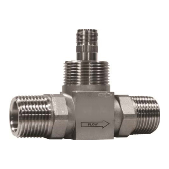
- Page 1 Turbine Flow Meter BP1100 Series Turbine Meter User Manual...
-
Page 2: Table Of Contents
Turbine Flow Meters, BP1100 Series CONTENTS Introduction . . . . . . . . . . . . . . . . . . . . . . . . . . . . . . . . . . . . . . . . . . . . . . . . . . . . . . . . . . . . . . . . . . . . . . . . . . 3 Operating Principle . -
Page 3: Introduction
Introduction INTRODUCTION Designed to withstand the demands of the most rigorous flow measurement applications, the Model BP1100 turbine flow meter is reliable, rugged and cost effective . Originally developed for the secondary oil recovery market, the Model BP1100 is an ideal meter for liquid flow measurement on or off the oil field . The meter features a rugged 316 stainless steel housing and rotor support assemblies, CD4MCU stainless steel rotor, and abrasive-resistant tungsten carbide rotor, shaft, and journal bearings . -
Page 4: Specifications
Though the meter is designed to function in any position, where possible, install it horizontally with the conduit adapter facing upward . 3 . Thread a magnetic pickup (Pembina model BP111109 or equivalent) into the conduit adapter completely finger tight without forcing . Secure with a lock nut if supplied . - Page 5 . Pembina Controls Inc. recommends installation of a minimum straight pipe length, equal to ten (10) pipe diameters on the upstream side and five (5) diameters on the downstream side of the flow meter . Otherwise, meter accuracy may be affected .
- Page 6 Installation BP3000 Electronic Flow Monitor Isolation and Isolation Valve Flow Rate Control Valve 10 Pipe Turbine 5 Pipe Diameters Flow Meter Diameters Bypass Valve Figure 3: Meter installation with a bypass line BP3000 Electronic Flow Monitor Control Valve 10 Pipe Turbine 5 Pipe Diameters...
-
Page 7: Pressure Drop In Water
Pressure drop in water PRESSURE DROP IN WATER Pressure Drop vs Flow Rate Pressure Drop vs Flow Rate 3/8” 3/4” 1” 2” 4” 8” 1/2” 7/8” 1-1/2” 3” 6” 10” 1/2” 7/8” 1-1/2” 3” 6” 10” 3/8” 2” 4” 3/4” 1”... -
Page 8: Turbine Replacement
Turbine replacement TURBINE REPLACEMENT The Model BP1100 turbine flow meter uses wear-resistant moving parts to provide trouble-free operation and long service life . Designed for easy field service of a damaged flow meter, Model BP1100 repair kits replace only the internal parts, not the entire flow meter . -
Page 9: Disassembly
Turbine replacement Disassembly 1 . Refer to Figure Figure 8 Figure 9 for relative positions of repair kit components . 2 . Remove the magnetic pickup from the meter body to avoid damage during repair . 3 . Remove the retaining ring from one end of the meter . 4 . -
Page 10: New Turbine Kit Installation
NOTEE: At this time, electronics require recalibration . Refer to the display's user manual . If there are any questions on recalibration, contact Pembina Controls Inc . or the manufacturer of the associated electronics . 6 . Install the magnetic pickup . -
Page 11: Part Number Information
Part number information PART NUMBER INFORMATION Flow Ranges Approx. Meter Part End Connec- Max. Strainer End to End Bore Size K-factor Weight Number tions Mesh Length gpm (lpm) m3/d Pulse/Gal (lb) 3/8 in . 0 .6…3 3 .00 in . BP110-375-½... -
Page 12: Troubleshooting Guide
. The Pembina BP1100 is proprietary to Pembina Controls Inc. and a private labeled Blancett product. Blancett is a registered trademark of Badger Meter, Inc. Other trademarks appearing in this document are the property of their respective entities. Due to continuous research, product improvements and enhancements, Badger Meter reserves the right to change product or system specifications without notice, except to the extent an outstanding contractual obligation exists.