
Related Manuals for Major Science SmartView Pro 2300

Summary of Contents for Major Science SmartView Pro 2300
- Page 1 SmartView Pro 2300/2400 Imager System Instruction Manual Catalogue No. UVCI-2300 UVCI-2400 www.majorsci.com service@majorsci.com Version 07A Revised on : 2018/11/07...
-
Page 2: Packing List
- 4 x M3 screws Signed by: Date: Major Science is liable for all missing or damaged parts / accessories within 7 days after customer received this instrument package. Please contact Major Science immediately regarding this issue. If no response within such time period from consignee party, that will be consignee party’s whole responsibility. -
Page 3: Table Of Contents
Table of Contents Packing list ..................... 1 Warning ......................6 Introduction ..................12 1.1 Overview ....................12 1.2 Feature ....................12 1.3 Components Guide ................13 Technical Specification ..............14 Installation Instructions ..............16 3.1 Installing Blue Light Plate (Optional) ............ 16 3.2 Installing White Light Plate (Optional) ........... - Page 4 4.8.7 Copy All to USB ..............51 4.8.8 Delete Selected ..............52 4.8.9 Delete All ................52 4.8.10 Screen Saver ................ 52 4.8.11 Create Folder ................ 52 4.8.12 Remove Folder ..............53 4.8.13 Network Settings..............54 4.9 Reverse out ..................54 4.10 Freeze ....................
- Page 5 4.8.5 Optional Devices..............76 4.8.6 Copy to USB ................76 4.8.7 Copy All to USB ..............76 4.8.8 Delete Selected ..............77 4.8.9 Delete All ................77 4.8.10 Screen Saver ................ 77 4.8.11 Create Folder ................ 77 4.8.12 Remove Folder ..............78 4.8.13 Network Settings..............
- Page 6 Ordering Information ..............141 Warranty ..................142...
-
Page 7: Warning
Warning Warning This device complies with Part 15 of the FCC Rules. Operation is subject to the following two conditions: (1) this device may not cause harmful interference, and (2) this device must accept any interference received, including interference that may cause undesired operation. NOTE: This equipment has been tested and found to comply with the limits for a Class B digital device, pursuant to Part 15 of the FCC Rules. - Page 8 Warning Major Science SmartView Pro Imager System series has been tested and found to comply with the limits for the CE regulation. Also, SmartView Pro Imager System series is RoHS compliant to deliver confident product which meets the environmental directive. These limits are designed to provide reasonable protection against harmful interference when the instrument series is operated in a commercial environment.
- Page 9 Follow the guidelines below to ensure safe operation of the unit. SmartView Pro Imager System series has been designed to use with shielded wires thus minimizing any potential shock hazard to the user. Major Science recommends against the use of unshielded wires.
- Page 10 1. Carry the device at least two people. 2. Do not over than knuckle height when you moving the device. 3. Move the device by cart and assist the device do not drop. Symbols The symbols used on SmartView Pro 2300 Imager System are explained below.
- Page 11 Warning Indicates an area where a potential shock hazard may exist. Consult the manual to avoid possible personal injury or instrument damage. Indicate a warning of UV radiation. While using the UV Transilluminator, be sure the operating personnel is properly protected. Indicates disposal instruction.
- Page 12 Warning 2. Preventative measures of risk Potential Risk Preventive measures Do not put the machine near the table edge. Bruise Move the machine by cart. Pinch Do not put your hands on the open door. Slash Prevent hard impact on the acrylic panel. radiation Do not open the darkroom door while you turn on the dangerous...
-
Page 13: Introduction
Introduction 1 Introduction 1.1 Overview SmartView Pro Imager System is the next generation of gel documentation instrument. It is specifically designed for ease of use for any lab experiment with gel imaging. SmartView Pro Imager System is packed with 2.0 megapixels high sensitivity and resolution scientific grade camera for outstanding imaging quality. -
Page 14: Components Guide
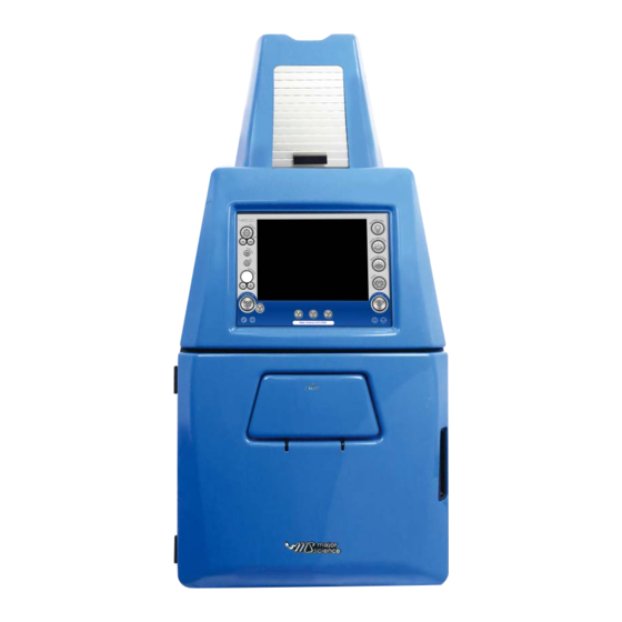
1.3 Components Guide 1.3 Components Guide Front View CCD camera and lens Touch panel Darkroom door Viewing window Inching switch of the door (UVCI-2300 only) USB port Ethernet Port Power switch Power socket & Fuse holder Rear View Side View... -
Page 15: Technical Specification
Specification 2 Technical Specification Model Name UVCI-2300 UVCI-2400 Total Weight Approx. 32.34 kg Approx. 25.4 kg Unit Dimension 400× 425 × 900 mm 410 × 405 × 915 mm (W × D × H) Display 10" TFT display Touch Sceen Image capture Download Images USB or web... - Page 16 Specification Manual Zoom Lens Operation Range Iris Manual control, F1.2-F16C Operation Range Focus Manual control, 1m - Inf. Operation Range Zoom Manual control, 12.5mm - 75mm Filter size M55mm Close-up Lens +1 close up ★ Filter (for camera) Ordered Separately ...
-
Page 17: Installation Instructions
3.1-3.2 Installing Optional Light Plate Installation Instructions SmartView Pro Imager System comes with epi white light and trans-UV (UVCI-2300) as standard. Optional blue light plate or white light plate is offered for expansion to offer higher flexibility. There are few procedures to install the optional devices: place the unit on a sturdy, level safe and dry place, then follow the instruction below for installation. - Page 18 3.1-3.2 Installing Optional Light Plate Step2 Open the darkroom door. *The Blue Light Plate will be installed under the White Light Plate. White Light Plate Blue Light Plate Step3 Fasten the Blue Light Plate onto device with a regular screwdriver and four screws.
- Page 19 3.1-3.2 Installing Optional Light Plate Step4 Connect the Blue Light Plate cable to darkroom inner socket. NOTICE: Blue Light Plate cable connects to the upper socket. Finished...
-
Page 20: Installing White Light Plate (Optional)
3.1-3.2 Installing Optional Light Plate 3.2 Installing White Light Plate (Optional) Step1 Get the White Light Plate ready. Step2 Open the darkroom door. Place the White Light Plate as the picture below. Align four screw holes (in yellow circles). White Light Plate... - Page 21 3.1-3.2 Installing Optional Light Plate Step3 Fasten the White Light Plate onto device with a regular screwdriver and four screws. Step4 Connect the White Light Plate cable to darkroom inner socket. NOTICE: White Light Plate cable connects to the lower socket. Finished...
- Page 22 3.1-3.2 Installing Optional Light Plate Note: If necessary, please manually adjust the aperture to have the best performance while working with White Light Table. Aperture ring F1.2 - Close...
-
Page 23: Installing Smartview 1D Analysis Software
3.3 Installing SmartView 1D Analysis Software 3.3 Installing SmartView 1D Analysis Software *To install the program, please log in as an administrator on the computer. Please refer to the Web link to change the account of computer: a. For Windows® XP http://www.microsoft.com/resources/documentation/windows/xp/all/proddocs/en-us/windows_ security_runas.mspx?mfr=true b. - Page 24 3.3 Installing SmartView 1D Analysis Software Step2 Activate SmartView 1D Analysis Software installation program. Step3 Click ”Next” to proceed. Step4 Accept the license agreement then press “Next” to proceed.
- Page 25 3.3 Installing SmartView 1D Analysis Software Step5 Save this program in your specifying location then press “Next” to proceed. Step6 Click “Install” to begin the installation.
- Page 26 3.3 Installing SmartView 1D Analysis Software Step7 Press "Finish" to complete the program installation. Step8 A dialog will pop up to ask you to restart your system, press “Yes” to restart now or “No” if you plan to manually restart later. Note: Please restart the computer when you have all needed software installed.
- Page 27 3.3 Installing SmartView 1D Analysis Software Step9 The SmartView 1D Analysis Software icon will be shown on desktop. Step10 Click to open SmartView 1D Analysis Software. For the first installation, you will need to enter the corresponding IP address of your device and license key.
- Page 28 3.3 Installing SmartView 1D Analysis Software NOTICE: You may find your IP address by checking your UVCI-2300/2400 interface> System Setup> IP address. Find your license key as following instruction. License Key Note: The license key must match the camera serial number. Note: Do not unplug the Ethernet cord of SmartView Pro Imager System when you operate the analysis software.
-
Page 29: Ip Address Setup
Operation Instruction-UVCI-2300 3.3.1 IP Address Setup In some cases, user might not be able to connect the remote control when user completes all the installation. So we suggest user check the IP address of user’s computer. Follow the instructions below. Step1 Open “Control Panel”... - Page 30 Operation Instruction-UVCI-2300 Step2. Click on “Change adapter settings”. User can see the connected LAN (Local Area Network). “Enabled” means the network that user’s computer is using, and the network is connected. Step2-1 Step2-2...
- Page 31 Operation Instruction-UVCI-2300 Step3. Right click on the connected network, and select “Properties”. The Network properties dialogue will pop up on the screen. Step3 Step4. Select “Internet Protocol Version 4 (TCP/IPv4)”; then click “Properties” Step4-1 Step4-2...
- Page 32 Operation Instruction-UVCI-2300 Step5. Check the IP address of user’s computer to see if user’s computer IP conflicts with the IP address of UVCI-2300/2400 or other computers. To set up a new IP address, the first 3 numbers should be the same as the first 3 numbers of user’s network IP address.
- Page 33 Operation Instruction-UVCI-2300 For example, if the IP address of the conflicted IP address is “10.0.0.103”, and the UVCI-2300/2400 IP address is “10.0.0.166”. Then the IP address of user’s computer should be set up like “10.0.0.152”. User can use the numbers ranging from 1 to 254 except 103 (the conflicted IP address) and 166 (the UVCI-2300/2400 IP address).
- Page 34 Operation Instruction-UVCI-2300 Step6. After finishing the setting, press “OK” to confirm the settings and exit the dialogue.
-
Page 35: Ip Address Confirm
Operation Instruction-UVCI-2300 3.3.2 IP Address Confirm To confirm the new IP address. Follow the next step. Step7. Click on the “Start” button. Type “cmd” in the search bar and press “Enter” key to execute the program. MS-DOS will pop up on the screen. - Page 36 Operation Instruction-UVCI-2300 Step8. Type “ipconfig” after the flashing cursor. And press “Enter” key. Step9. System then shows the IP address of user’s, the example in step 5, user’s IP has been changed to “10.0.0.152”, therefore the same IP address is showed in the screen.
- Page 37 Operation Instruction-UVCI-2300 Step10. Then type “ping + (Space) + UVCI-2300/2400’s IP address” right after the flashing cursor. For instance, the IP address of the used UVCI-2300/2400 is “10.0.0.166”; then type “ping 10.0.0.166”, and press “Enter”. Step11. The program will start connecting user’s computer to UVCI-2300/2400. The information showed on the screen tells user if the network is connected.
- Page 38 Operation Instruction-UVCI-2300 This means the network is working--computer and controller are not connecting to each other. If the network is still not connected, please check the connection and settings of user’s network equipment.
-
Page 39: Operation Instructions
Operation Instruction-UVCI-2300 4 Operation Instructions HMI Interface (UVCI-2300) 4.1 Start the System Plug on power cord to your socket. Turn on device via the power switch on side of UVCI-2300. Opening Interface... - Page 40 Operation Instruction-UVCI-2300 HMI Interface (optional devices disabled) HMI Interface (optional devices enabled) (With “white light plate” and “blue light plate” optional devices connected)
-
Page 41: Select The Uv Intensity
Operation Instruction-UVCI-2300 4.2 Select the UV Intensity Press “UV” icon to turn on or off UV transilluminator, select 70/100 (%) to set the UV light intensity. 4.3 Add Info Press “Add Info” icon to enable the function of date, exposure time stamp on the left corner of picture and the title on the middle above. -
Page 42: Title
Operation Instruction-UVCI-2300 4.4 Title Press “Title” icon to rename the title. 4.5 Adjust the Volume of Exposure Key in the desired value of exposure time (0.001-30 sec.) - Page 43 Operation Instruction-UVCI-2300 Press”+” or”-“under the column of “Exposure” to increase/decrease 0.001 sec. of the value of exposure user sets.
-
Page 44: Capture
Operation Instruction-UVCI-2300 4.6 Capture Press “Capture” icon to capture a picture at the present. The capture dialogue would pop out. -
Page 45: Save Pictures To Remote Computer
Operation Instruction-UVCI-2300 (A) Select either “Internal disk” or “External USB” to decide the loction of the storage. (B) Tap the button behind “Save in folder” to choose the folder that desired to be saved. Note: Users could create their own folder up to 3 layers of folder. Please go to System Setup>... - Page 46 Operation Instruction-UVCI-2300 NOTICE: You may find your IP address by checking your UVCI-2300/2400 interface> System Setup> IP address. Input the user name and the password. NOTICE: You may find and change your user name and password by checking your UVCI-2300/2400 interface> Default Setting>Remote login.
-
Page 47: Default Setting
Operation Instruction-UVCI-2300 4.7 Default Setting Press to open “Default Setting” dialogue. In “Default Setting” page, user can set various items as default setting. See detailed description below. Start up settings In this column, user can set the lighting module on or off as default setting. Also, user can set the intensity of UV light ( UVCI-2300 only), its auto-shut-off time, and the default exposure time. - Page 48 Operation Instruction-UVCI-2300 Advanced features Here user could set “Saturation detection” on/off and its value as default setting. NOTICE: If the current saturation value is above the set value and the mechanism is on, this signal picture will show beside “Default Setting” button. In case user accidentally delete all the files, the default setting of “Delete all”...
-
Page 49: System Setup
Operation Instruction-UVCI-2300 4.8 System Setup Press “System Setup” icon and open the system setup page. See detailed description in the following sections. System Setup Page... -
Page 50: Touch Screen Calibration
Operation Instruction-UVCI-2300 4.8.1 Touch Screen Calibration Press system will transfer to the page of screen calibration. Click the middle of the cross until finish the calibration process. After finish screen calibration process, system will return to the prior page automatically. 4.8.2 System Information Press to read... -
Page 51: System Time
Operation Instruction-UVCI-2300 4.8.3 System Time Press icon read or set system time. Press ”Set” save “Cancel” to cancel and close the dialogue. 4.8.4 System Upgrade If there is a need of system upgrade, plug the USB with the upgrade file in and press If user does not plug in the USB or the USB does not contain the corresponding... -
Page 52: Optional Devices
Operation Instruction-UVCI-2300 Plug the USB with upgrade file, system will pop up a warning to confirm, press “Yes” to continue or “No” to cancel. NOTE: System will reboot automatically after upgrade. 4.8.5 Optional Devices Press to enable the optional devices. Press and turn on/off the lighting module. -
Page 53: Delete Selected
Operation Instruction-UVCI-2300 4.8.8 Delete Selected If user would like to delete any file. Select the files and press 4.8.9 Delete All If user would like to delete all files, press . System will delete all files automatically. Note: User has to enable this function in Default Setting first; otherwise this button will not show up. -
Page 54: Remove Folder
Operation Instruction-UVCI-2300 4.8.12 Remove Folder If user would like to delete any folder in the list, select the folders and press... -
Page 55: Network Settings
Operation Instruction-UVCI-2300 4.8.13 Network Settings Press to set detail information. Press “Apply” to apply or “Cancel” to cancel and close the dialogue. 4.9 Reverse out Press the icon to reverse the color of present picture from black to white, white to black. -
Page 56: Freeze
Operation Instruction-UVCI-2300 4.10 Freeze Press to freeze the present picture on the screen. System will have the picture stay on the screen as long as user needs. If user would like to save the freeze picture, press “Capture” and press “Save”. During the period of “freeze,”... -
Page 57: Turn On/Off The Lighting Modules
Operation Instruction-UVCI-2300 4.11 Turn ON/OFF the Lighting Modules Press the icon of “Epi White Light” to turn on/off the Epi white light. Press the icon of “White Light Plate” to turn on/off the white light. Press the icon of “Blue Light Plate” to turn on/off the blue light. -
Page 58: Print
Operation Instruction-UVCI-2300 4.12 Print Press the icon of “Print” to print the present picture on the screen. NOTICE that system will not save a digital format of the picture automatically only by pressing “Print” button. 4.13 Load and Edit the Picture Press “Load”... - Page 59 Operation Instruction-UVCI-2300 Editing Interface Close/Cancel Save Anti-white Flip upside down Flip horizontally Turn counterclockwise Turn clockwise Brightness adjust Crop Text...
-
Page 60: Anti-White
Operation Instruction-UVCI-2300 4.13.1 Anti-white Press to anti-white the screen. 4.13.2 Flip upside down Press to turn the picture upside down. 4.13.3 Flip horizontally Press to flip the picture horizontally. -
Page 61: Turn Counterclockwise
Operation Instruction-UVCI-2300 4.13.4 Turn counterclockwise Press to turn the picture counterclockwise. 4.13.5 Turn clockwise Press to turn the picture clockwise. 4.13.6 Brightness adjust Press to increase or decrease the brightness of the picture. -
Page 62: Crop
Operation Instruction-UVCI-2300 4.13.7 Crop Press to crop the picture. Press one point on the screen and drag to crop. NOTICE: The minimum area of cropping is 256*256 pixels. If the crop square shows red, it is too small; if it is green, it is in possible size. - Page 63 Operation Instruction-UVCI-2300 3. Press to edit the content of the text. Press “Create” to apply the setting. Note: all letters are in capital. “Esc” is to delete all text in column; backspace. Press “Cancel” to cancel editing and close 4. Press to adjust the front size.
-
Page 64: Undo And Redo
Operation Instruction-UVCI-2300 4.13.9 Undo and redo On the editing page, any changing can be undone or redone by buttons along right bar. 4.14 Signals Indication CCD Camera Connected Door Opened Printer Connected USB Enabled 4.13 WARNINGS: If the UV transilluminator is on while the door is opened, UV light will be turned off automatically, and the warning will pop up to warn users that the UV light is harmful to... -
Page 65: Hmi Interface (Uvci-2400)
Operation Instruction-UVCI-2400 HMI Interface (UVCI-2400) 4.1 Start the System Plug on power cord to your socket. Turn on device via the power switch on side of UVCI-2400. Opening Interface... - Page 66 Operation Instruction-UVCI-2400 HMI Interface (optional device disabled) HMI Interface (optional device enabled) (With optional device “white light plate” connected)
-
Page 67: Add Info
Operation Instruction-UVCI-2400 4.3 Add Info Press “Add Info” icon to enable the function of date, exposure time stamp on the left corner of picture and the title on the middle above. If user wants to show only certain item, press to enter Default Setting>Add Info for further changing. -
Page 68: Adjust The Volume Of Exposure
Operation Instruction-UVCI-2400 4.5 Adjust the Volume of Exposure Key in the desired value of exposure time (0.001-30 sec.) Press”+” or”-“under the column of “Exposure” to increase/decrease 0.001 sec. of the value of exposure user sets. -
Page 69: Capture
Operation Instruction-UVCI-2400 4.6 Capture Press “Capture” icon to capture a picture at the present. (A) Select either “Internal disk” or “External USB” to decide the loction of the storage. (B) Tap the button behind “Save in folder” to choose the folder that desired to be saved. -
Page 70: Save Pictures To Remote Computer
Operation Instruction-UVCI-2400 (C) Type the file name(system default is the date and time of the picture been taken). The file can be named up to 128 characters. Select either “8 bit” or “16 bit” and the file format user would like to save. Note: All file format can be saved as 8 bit while only tiff and png can be saved as 16 bit. - Page 71 Operation Instruction-UVCI-2400 3. Input the user name and the password. NOTICE: You may find and change your user name and password by checking your UVCI-2300/2400 interface> Default Setting>Remote login. 4. List of current pictures saved in “Internal disk” then could be viewed and saved from the computer.
-
Page 72: Default Setting
Operation Instruction-UVCI-2400 4.7 Default Setting Press to open ”Default Setting” dialogue. In “Default Setting” page, user can set various items as default setting. See detailed description below. Start up settings In this column, user can set the lighting module on or off as default setting. User can set the auto-shut-off time of white light, and the default exposure time. - Page 73 Operation Instruction-UVCI-2400 Advanced features Here user could set “Saturation detection” on/off and its value as default setting. NOTICE: If the current saturation value is above the set value and the mechanism is on, this signal picture will show beside “Default Setting” button. In case user accidentally delete all the files, the default setting of “Delete all”...
-
Page 74: System Setup
Operation Instruction-UVCI-2400 4.8 System Setup Press “System Setup” icon and open the system setup page. See detailed description in the following sections. System Setup Page... -
Page 75: Touch Screen Calibration
Operation Instruction-UVCI-2400 4.8.1 Touch Screen Calibration Press system will transfer to the page of screen calibration. Click the middle of the cross until finish the calibration process. After finish screen calibration process, system will return to the prior page automatically. 4.8.2 System Information Press to read... -
Page 76: System Time
Operation Instruction-UVCI-2400 4.8.3 System Time Press icon read or set system time. Press ”Set” save “Cancel” to cancel and close the dialogue. 4.8.4 System Upgrade If there is a need of system upgrade, plug the USB with the upgrade file in and press If user does not plug in the USB or the USB does not contain the corresponding... -
Page 77: Optional Devices
Operation Instruction-UVCI-2400 Plug the USB with upgrade file, system will pop up a warning to confirm, press “Yes” to continue or “No” to cancel. NOTE: System will reboot automatically after upgrade. 4.8.5 Optional Devices Press to enable the optional devices. Press and turn on/off the lighting module. -
Page 78: Delete Selected
Operation Instruction-UVCI-2400 4.8.8 Delete Selected If user would like to delete any file. Select the files and press 4.8.9 Delete All If user would like to delete all files, press . System will delete all files automatically. Note: User has to enable this function in Default Setting first; otherwise this button will not show up. -
Page 79: Remove Folder
Operation Instruction-UVCI-2400 4.8.12 Remove Folder If user would like to delete any folder in the list, select the folders and press... -
Page 80: Network Settings
Operation Instruction-UVCI-2400 4.8.13 Network Settings Press to set detail information. Press “Apply” to apply or “Cancel” to cancel and close the dialogue. -
Page 81: Reverse Out
Operation Instruction-UVCI-2400 4.9 Reverse out Press the icon to reverse the color of present picture from black to white, white to black. 4.10 Freeze Press to freeze the present picture on the screen. System will have the picture stay on the screen as long as user needs. If user would like to save the freeze picture, press “Capture”... -
Page 82: Turn On/Off The Lighting Modules
Operation Instruction-UVCI-2400 4.11 Turn ON/OFF the Lighting Modules Press the icon of “Epi White Light” to turn on/off the Epi white light. Press the icon of “White Light Plate” to turn on/off the white light. Press the icon of Blue Light” to turn on/off the blue light. -
Page 83: Print
Operation Instruction-UVCI-2400 4.12 Print Press the icon of “Print” to print the present picture on the screen. NOTICE that system will not save a digital format of the picture automatically only by pressing “Print” button. 4.13 Load and Edit the Picture Press “Load”... - Page 84 Operation Instruction-UVCI-2400 Editing Interface Close/Cancel Save Anti-white Flip upside down Flip horizontally Turn counterclockwise Turn clockwise Brightness adjust Crop Text...
-
Page 85: Anti-White
Operation Instruction-UVCI-2400 4.13.1 Anti-white Press to anti-white the screen. 4.13.2 Flip upside down Press to turn the picture upside down. 4.13.3 Flip horizontally Press to flip the picture horizontally. -
Page 86: Turn Counterclockwise
Operation Instruction-UVCI-2400 4.13.4 Turn counterclockwise Press to turn the picture counterclockwise. 4.13.5 Turn clockwise Press to turn the picture clockwise. 4.13.6 Brightness adjust Press to increase or decrease the brightness of the picture. -
Page 87: Crop
Operation Instruction-UVCI-2400 4.13.7 Crop Press crop picture. Press one point on the screen and drag to crop. 4.13.8 Text 1. Press to create a new text on the picture. Locate one point and press to add a new text. Cross indicates the location of the text. - Page 88 Operation Instruction-UVCI-2400 3. Press to edit the content of the text. Press “Create” to apply the setting. Note: all letters are in capital. “Esc” is to delete all text in column; backspace. Press “Cancel” to cancel editing and close 4. Press to adjust the front size.
-
Page 89: Undo And Redo
Operation Instruction-UVCI-2400 4.13.9 Undo and redo On the editing page, any changing can be undone or redone by buttons along right bar. 4.14 Signals Indication CCD Camera Connected Door Opened Printer Connected USB Enabled... -
Page 90: Smartview 1D Analysis Software
SmartView 1D Analysis Software 5 SmartView 1D Analysis Software 5.1 Process SmartView 1D Analysis Software 2.-13. a. Open the data file. b. Save the file. c. Exit the program. - Page 91 SmartView 1D Analysis Software Step: Next Step: Go to next step to select analysis mode: gel positive/ gel negative/ dot positive/ dot negative. Process: Crop: Select the cropping area of the image. Rotate: Rotate the image. Flip: Flip the image according to the orientation you desired. Brightness: Adjust the brightness of the image.
- Page 92 SmartView 1D Analysis Software Crop: Crop the image by press the “Crop” button (as box 1). In order to select the cropping area of the image, hold and drag the cursor to select the area you want (as box 2). Once you are done. Press “” (as box 3) button to confirm or press “x”...
- Page 93 SmartView 1D Analysis Software SmartView 1D Analysis Software You may rotate the image counter-clock wise or clock wise in two ways: a. Using the toolbar labelled as box 1, press "" to confirm action. b. Input the desired angle (0~359) directly in the blank space labelled as box 2, press ENTER first before pressing ""...
- Page 94 SmartView 1D Analysis Software Flip: To flip the image according to the orientation you desired. : Invert the image upside down. SmartView 1D Analysis Software : Invert the image from left to right. SmartView 1D Analysis Software...
- Page 95 SmartView 1D Analysis Software : Confirm action : Cancel Brightness: Adjusting the brightness of the image by pressing on the “Brightness” button (as box 1), then use the scrollbar (as box 2) to adjust the brightness level. : Low – High SmartView 1D Analysis Software The result of Brightness is shown below.
- Page 96 SmartView 1D Analysis Software Contrast: Adjusting the contrast level of the image by pressing the “Contrast” button (as box 1), then use the scrollbar (as box 2) to adjust the contrast level. : Low – High SmartView 1D Analysis Software The result of Contrast is shown below.
- Page 97 SmartView 1D Analysis Software SmartView 1D Analysis Software Negative: To reverse the image between black and white by pressing on the “Negative” button (as box 1). If you don’t want to negative the image, you can press the “Negative” button again or you can press the “Undo” button (as box 2) to recover the image.
- Page 98 SmartView 1D Analysis Software Zoom: Adjusting the zoom of the image by pressing on the “Zoom” button (as box 1) and then a toolbar will pop out. If you want to zoom in the image, press the ”+” button (as box 2). If you want to zoom out the image, press the “-“ button (as box 2).
- Page 99 SmartView 1D Analysis Software Text: You could add any text onto the image. Click on the “Text” button (as box 1) and then the toolbar (as box 2) will show up. The sample text (as box 3) will show on middle of the screen.
- Page 100 SmartView 1D Analysis Software Input box: Type in your text here, press ENTER first before pressing "" to confirm action. : Confirm action : Cancel Note: 1. To add another set of text, please press "TEXT" again. 2. To remove a text, please use “Undo”. Original: This is the master undo button.
- Page 101 SmartView 1D Analysis Software Next Step: Press “Next Step” button (as box1) to continue the analysis. There are 4 analysis methods for you to choose depending on your application. For example here, we choose “Gel Negative” (as box 2) for DNA gel electrophoresis. (This instruction for operating under Gel Positive and Gel Negative is the same) SmartView 1D Analysis Software...
-
Page 102: Editor
SmartView 1D Analysis Software 5.2 Editor SmartView 1D Analysis Software 1.-4. Step: Previous Step: Return to previous step, current setting will be deleted. Next Step: Go to next step. Editor: Add Lane: Add the lane to analysis. Delete Lane: To cancel the lane. -
Page 103: Selecting The Image Lane
SmartView 1D Analysis Software Note: Make sure to add all lanes you wish to analyze before you proceed to the next step. 5.3 Selecting the Image Lane Add Lane: Selecting your lane by creating a long rectangular box along the lane. Press “Add Lane”... - Page 104 SmartView 1D Analysis Software Delete Lane: Press “Del Lane” button (as box 1), and then click the center of rectangular box you want to delete. After selecting all lanes, click “Next Step” button (as box 2) to move forward. Note: Make sure your bands are straight and enclosed inside the rectangular box.
-
Page 105: Analyze
SmartView 1D Analysis Software 5.4 Analyze SmartView 1D Analysis Software 1.-9. - Page 106 SmartView 1D Analysis Software Step: Previous Step: Return to previous step, current setting will be deleted. Next Step: Go to next step. Home: Return to Image Process Interface. Analyze: Auto Find: Find the peaks automatically. Add Peak: Add the peak manually. Delete Peak: Delete the peak manually.
- Page 107 SmartView 1D Analysis Software The analysis software will analyze the bands inside the lane to create a histogram. SmartView 1D Analysis Software Auto Find: Click on the “Auto Find” button (as box 1), the software will allow you to adjust the sensitivity level according to your needs.
- Page 108 SmartView 1D Analysis Software Any peaks above your adjusted sensitivity level will turn “RED”. Example A: Sensitivity level 1 SmartView 1D Analysis Software Example B: Sensitivity level 10 SmartView 1D Analysis Software If the density of band (as box 1) is not clear, the Auto Find (as box 2) function...
- Page 109 SmartView 1D Analysis Software cannot find any peaks. The warning dialogue will pop up on the screen (as box 3). SmartView 1D Analysis Software Add Peak: Click “Add Peak” button (as box 1), choose two points which covers the range of the peak from the screen (select one point from the left side and a second point from the right side of the desired peak) to add a peak (as box 2) and then click the “”.
- Page 110 SmartView 1D Analysis Software The peak will turn “RED”. The new peak number is 5 (shown below). SmartView 1D Analysis Software Delete Peak: Press “Delete Peak” button (as box1), click on that peak (as box 2), the peak will turn gray and then click “” to finished. SmartView 1D Analysis Software...
- Page 111 SmartView 1D Analysis Software The peak will turn white. The white peak will not be included in the calculation. The order of the peaks will be rearranged. SmartView 1D Analysis Software...
- Page 112 SmartView 1D Analysis Software Base Line: This feature is used to help you increase (or cut off) the peaks you want (or do not want) to include in the quantification step. Press “Base Line” button (as box 1) a green line will show up on the screen, you could move the line to the position you desiredand the peaks above the base line will be selected, then press “”...
- Page 113 SmartView 1D Analysis Software The software will only count the peaks that are above the base line. There were three lanes selected (as box 1) in this example, so you need to press on the “Next Lane” button (as box 2) go to select peaks for lane3 before proceeding to summarizing the data.
-
Page 114: Summary
SmartView 1D Analysis Software 5.5 Summary SmartView 1D Analysis Software 1.-2. Step: Previous Step: Return to previous step, current setting will be deleted. Home: Return to Image Process Interface. - Page 115 SmartView 1D Analysis Software Calculating the density Step1 When clicking the “Density” worksheet (as box 1), you need to input two known concentration from two of the bands from the lane(s). Step2 Double click the blank L1 Concentration box associated with the known marker size.
- Page 116 SmartView 1D Analysis Software Step3 Entering the second value of known concentration then hit Enter on your keyboard to finish, the analysis software will project all the other unknown concentrations based on the 2 known (input) concentrations. Step4 Click “Save image” button (as box 1) to store this image from the screen. Choose a destination location to save your image.
- Page 117 SmartView 1D Analysis Software Step5 Click on the “Export Data” button (as box1), a window pops up to ask you to select a destination location to save your file. Give the data a file name (as box 2) and press “Save” (as box 3). (Data is then exported using the CSV file format, which could be easily access by using Microsoft Excel)
- Page 118 SmartView 1D Analysis Software Calculating the molecular weight Step1 Select “Molecular weight” worksheet to move forward with quantification analysis by calculating the molecular weight. Step2 Key in the respective molecular weight values of the marker in this page. Note: The ”Mol weight” values of marker are provided by marker manufacturer.
- Page 119 SmartView 1D Analysis Software Step3 Fill in all known values of the marker on the list. Step4 Click “Save image” button (as box 1) to store this image from the screen. Choose a destination location to save your image. Give the image a file name (as box 1) and press “Save”...
- Page 120 SmartView 1D Analysis Software Step5 When clicking the “Mol Weight Calc.” button (as box1), this analysis software will calculate the unknown “Mol weight” based on the input marker values. Press the “Export Data” button (as box 2), the software will export the data to a CSV file sheet. Step6 Choose a destination location to save your export.
-
Page 121: Dot Blot Analysis Sample
Dot Blot Analysis Sample Crop: Crop the image by press the “Crop” button (as box 1). In order to select the cropping area of the image, hold and drag the cursor to select the area you want (as box 2). Once you are done. Press “” (as box 3) button to confirm or press “x”... - Page 122 The image will be shown below as you selected. * Remember: Always rotate the image before you crop. SmartView 1D Analysis Software Rotate: To rotate the image, first select the “Rotate” button (as box1) and the toolbar (as box 2) will pop up. Toolbar: : Rotate counter-clock wise : Rotate clock wise...
- Page 123 SmartView 1D Analysis Software You may rotate the image counter-clock wise or clock wise in two ways: a. Using the toolbar labelled as box 1, press "" to confirm action. b. Input the desired angle (0~359) directly in the blank space labelled as box 2, press ENTER first before pressing ""...
- Page 124 Flip: To flip the image according to the orientation you desired. : Invert the image upside down. SmartView 1D Analysis Software : Invert the image from left to right. SmartView 1D Analysis Software...
- Page 125 : Confirm action : Cancel Brightness: Adjusting the brightness of the image by pressing on the “Brightness” button (as box 1), then use the scrollbar (as box 2) to adjust the brightness level. : Low – High SmartView 1D Analysis Software The result of Brightness is shown below.
- Page 126 Contrast: Adjusting the contrast level of the image by pressing the “Contrast” button (as box 1), then use the scrollbar (as box 2) to adjust the contrast level. : Low – High SmartView 1D Analysis Software The result of Contrast is shown below. Press “” to proceed or press “x” to cancel. : Confirm action : Cancel...
- Page 127 SmartView 1D Analysis Software Negative: To reverse the image between black and white by pressing on the “Negative” button (as box 1). If you don’t want to negative the image, you can press the “Negative” button again or you can press the “Undo” button (as box 2) to recover the image.
- Page 128 Zoom: Adjusting the zoom of the image by pressing on the “Zoom” button (as box 1) and then a toolbar will pop out. If you want to zoom in the image, press the ”+” button (as box 2). If you want to zoom out the image, press the “-“button (as box 2).
- Page 129 SmartView 1D Analysis Software Click on the input box, type in your text here. You could adjust your text using this toolbar. The toolbar functions are explained as below. : Change the font type : Change the font size. : Move the text to the desired location by move the mouse cursor to the desired location on the image and click the left button of the mouse.
- Page 130 : Cancel Note: 1. To add another set of text, please press "TEXT" again. 2. To remove a text, please use “Undo”. Original: This is the master undo button. It will undo ALL the changes you made to the image and revert it back to the original image. A massage will pop up to ask for confirmation once you press the “Original”...
- Page 131 Next Step: Press “Next Step” button (as box1) to continue the analysis. There are 4 analysis methods for you to choose depending on your application. For example, we choose “Dot blot Positive” (as box 2) for DNA gel electrophoresis. (This instruction for operating under Dot blot Positive and Dot blot Negative is the same) SmartView 1D Analysis Software...
- Page 132 Selecting the Image Dot Press “Dot blot Positive” button and the software will automatically analyze the dot-blot samples from the image. SmartView 1D Analysis Software Add Dot: Click “Add Dot” button (as box 1) to add one sample. Use the mouse to select the sample (as box 2) from the screen.
- Page 133 The image will be shown below as you have selected. SmartView 1D Analysis Software Delete Dot: Press “Del Dot” button (as box 1), and then select the dot (as box 2) you want to delete. After selecting the dot, click on “Next Step” button (as box 3) to move forward to next step.
- Page 134 Calculating the density Step1 Double click on the “Dot concentration” blank boxes to input the real density of each sample. (You will need at least one value in order to calculate the rest of the numbers.) Step2 Enter the value of known concentration. The analysis software will project other unknown concentrations based on the known (input) concentration.
- Page 135 Step3 Click “Save image” button (as box 1) to store this image from the screen. Choose a destination location to save your image. Give the image a file name (as box 2) and press “Save” (as box 3) to finish. Step4 Click on the “Export Data”...
-
Page 136: Troubleshooting Guide
6 Troubleshooting Guide Many operating problems may be solved by carefully reading and following the instructions in this manual accordingly. Some suggestions for troubleshooting are given below. Should these suggestions not resolve the problem, please contact our SERVICE DEPARTMENT or a distributor in your region for assistance. - Page 137 *Note Unscrew the back panel of UVCI-2300/2400, reconnect the USB cable of CCD camera(refer to the picture below). PLEASE make sure to turn the system off before opening the back panel. CCD Camera Connect USB Cable Reconnect the USB port on the board and check again.
-
Page 138: Cleaning & Maintenance
7 Cleaning & Maintenance The painted surfaces of the filter areas on the built-in UV Transilluminator must be cleaned with water and soap, using a sponge or towel. Dry the filter surface with a soft cloth after each operation. Never use abrasive cleaners, solvent based cleaners or scouring pads. -
Page 139: Replacing Amber Filter On Viewing Window
7.2 Replacing Amber Filter on Viewing Window Two filters (transparent filter and amber filter) are installed as default, if you did not purchase the blue light module and would like to remove the amber filter, please follow the steps below. Tool: 7mm socket wrench (not provided) - Page 140 Step1 Loosen 4 nuts from the corners. Remove the transparent filter. Step2 There are no screw holes on the amber filter, please put the amber filter in between.
- Page 141 Step3 Replace the transparent filter, put the nuts of four corners and then use the socket wrench to tighten the nuts. Step4 Confirm the transparent filter is fixed in the center of the viewing window.
- Page 142 2300 & 2400 series UVCI-2300-BL Blue Light table for SmartView Pro 2300 series UVCI-2300-WL White Light Plate 21 × 26cm for SmartView Pro 2300 & 2400 series UVCI-1000-F4 Viewing window Amber filter, 580nm for SmartView Pro 1000 series...
- Page 143 This warranty excludes damages resulting from shipping, misuse, carelessness, or neglect. Consumable parts (UV lamp and UV filter) are not covered by our warranty. Major Science’s liability under the warranty is limited to the receipt of reasonable proof by the customer that the defect is embraced within the terms of the warranty.
- Page 144 MEMO...
Need help?
Do you have a question about the SmartView Pro 2300 and is the answer not in the manual?
Questions and answers