Table of Contents
Advertisement
Quick Links
Advertisement
Table of Contents

Related Manuals for arkmeds Luft

Summary of Contents for arkmeds Luft
- Page 1 VENTILATOR ANALYZER User Guide.
-
Page 3: Table Of Contents
Table of Contents INTRODUCTION ----------------------------------------------------- 4 SAFETY INFORMATION ------------------------------------------- 4 ACRONYMS AND DEFINITIONS --------------------------------- 5 PACKAGING ---------------------------------------------------------- 6 CONCEPTS --------------------------------------------------------- 7 UNDERSTANDING THE DEVICE ------------------------------ 10 TURNING ON THE DEVICE ------------------------------------- 14 TEST----------------------------------------------------------------- 24 BIDIRECTIONAL ------------------------ 25 UNIDIRETCIONAL ---------------------- 26 O2 CELL REPLACEMENT -------------------------------------- 27 SOFTWARE AND APPLICATION ------------------------------ 28 PROBLEMS AND SOLUTIONS -------------------------------- 29... -
Page 4: Introduction
It is integrated with the management system, enabling real-time integration and reading of the values tested, registering them in the device’s repair and maintenance records. Luft operates on a rechargeable lithium-ion battery, capable of lasting three to five hours of uninterrupted testing. -
Page 5: Acronyms And Definitions
If you notice any irregularity with the device, do not put it into operation. Depending on the problem, the device may suffer irreversible damage, which will lead to costly maintenance or discontinuity. Whenever the device fails, set it aside and contact the Arkmeds Support Team through the channel: https://www.arkmeds.us/support ACRONYMS AND DEFINITIONS •... -
Page 6: Packaging
PACKAGE CONTENT The Luft Mechanical Ventilation Analyzer package comes with the following items: 1 x Luft (PN 42000001) 1 x User Manual (PN 12000036) 1 x Calibration Certificate Accessories: 1 x Y-connector with hole (PN 11000064) 1 x Bacteriological filter (PN 11000074) -
Page 7: Concepts
CONCEITOS Mechanical Ventilation is a method adopted to support patients with respiratory failure, according to each clinical pathology present in this individual. There are some basic concepts present in this method, which need to be known by the technical professionals who will perform the calibration procedure, as follows: Calibration: a set of operations that establishes, under specified conditions, the relationship between the values indicated by an instrument... - Page 8 PCV: controlled pressure, ventilation performed with pressure control as the main parameter. The terminology may change depending on the manufacturer. Current Flow: airflow that passes through the flow sensor in the inspiratory and expiratory phases, according to the assembly adopted. Peak Flow: maximum flow value recorded at each cycle.
- Page 9 Oxygen Cell: electrochemical cell responsible for reading the oxygen concentration. Note: The electrochemical oxygen cell must be compatible with a MAX-16 R114P70 type cell that has a voltage output of 9 to 16mV for a linear range of 0 to 100% oxygen concentration. M16x1...
-
Page 10: Understanding The Device
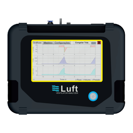
UNDERSTANDING THE DEVICE Next, the device will be shown with the identification of its connectors and controls. FRONT VIEW: Touch Screen. On/Off Button. - Page 11 UPPER VIEW Power cord with fuse holder. Internal charge connector (default 200ohm). External charge connector. Scalpel Input - Active Scalpel Input - Passive...
- Page 12 LEFT SIDE Flow gateway. RIGHT SIDE Flow gateway. Flow gateway.
- Page 13 BACK VIEW Serial number identifi cation tag.
-
Page 14: Turning On The Device
Press the “on/off” button to turn on the device. The device will perform internal communication tests and will display a screen with the Arkmeds logo and will show the following screen: SCREEN On the main screen, we will have the following access options: •... - Page 15 “Charts” Tab The charts tab displays the graphical reading of Flow, Volume, and Low Pressure. The chart shown on the screen can be configured by checking or unchecking the desired option in the lower right corner of the screen: Flow, Volume, or Pressure. Selecting the screen will auto-adjust the scales, zooming in on each curve.
- Page 16 “Measures” Tab The measures tab displays the numerical reading of the following parameters: On this screen, it is possible to perform the numerical reading of the following parameters:...
- Page 17 Unidades Faixa Precisão Parâmetros Flow L/min, ml/min, L/s, ml/s -200 slpm to +- 1.5% Tidal Volume mL, L 0 to 100L +- 2% Minute Volume L*rpm 0 to 1200Lpm +- 2% Low Pressure cmH2O, kPa, cmHg 0 to 1000 +- 2.5% High Pressure kPa, PSI, bar 0 to 700 kPa...
- Page 18 “Settings” Tab The settings tab presents the analyzer settings options, O2 cell calibration, connectivity, and language. It’s possible to adjust the trigger by selecting the settings tab andclicking on the Measurements option. This adjustment can be made in two ways: - Manual - Automatic To enable the automatic trigger mode, just uncheck the box next to Manual...
- Page 19 Understanding the Trigger The trigger indicates the start and endpoints of each inspiration and expiration to the analyzer software. It is possible to integrate the flow curve to obtain the volume reading and other parameters from this point. Trigger adjustment can be made by flow and pressure, always observing the dynamics for each of them.
- Page 20 Set Zero option. Moving Average Luft has an option to configure the use of a moving average. The system will perform some measurements according to the selected quantity and present the average of these values after the elapsed time.
- Page 21 When clicking on the “O2 Sensor” option on the “Settings” tab, the following screen will be displayed: On this screen, the user can calibrate the O2 Cell. To do that, follow the instructions 21% calibration -Leave the flow inlet and outlet open to the environment, for about three minutes;...
- Page 22 100% calibration Insert a continuous flow of O2 at the Luft flow inlet for about two minutes; After this time has elapsed, select the measure option located below the 100% oxygen option; Notes: A digital indicator of the cell reading can be observed at the top of the chart for both calibration procedures.
- Page 23 Battery Charge Level The battery charge level indicator is shown between the Freeze Screen and Output Option. It is recommended to keep the minimum charge level at 10% to 15% of the battery. Otherwise, it will be necessary to perform a battery reset procedure (Read more in Defects and Solutions).
-
Page 24: Test
Notes: ALWAYS turn off the device as indicated above. Turning off directly through the switch can cause DAMAGE to the software. TEST Iremos demonstrar nesta seção como será realizada a montagem do circuito juntamente com o analisador LUFT. A realização dos ensaios podem ser feitas na configuração unidirecional e bidirecional. -
Page 25: Bidirectional
1. Connect the tracheas of the inspiratory and expiratory branches through the Y-connector. 2. Connect the output of the Y connector to the Luft inlet port through an adapter or small trachea. 3. Connect a low-pressure line of the Y connector to the Low-Pressure inlet port. -
Page 26: Unidiretcional
1. Connect the trachea of the inspiratory branch to the fl ow inlet. 1. Connect the trachea of the inspiratory branch to the fl ow inlet. 2. Connect a small breathing tube or adapter at the Luft fl ow outlet and join on one side of the Y connector. -
Page 27: O2 Cell Replacement
Note: multiple connections in the assembly can make the flow more turbulent and consequently generate more noise in the flow reading. Always opt for a simpler assembly, also avoiding dead space with the use of smaller tracheas. O2 CELL REPLACEMENT The user can replace the O2 Cell if a change in the reading is identified. -
Page 28: Software And Application
REL IE B ATM PRESSURE REMOTE ACCESS If your device has a problem, Luft has the option of remote access that allows a better understanding of the failure in the field and its appropriate corrections, if applicable, in addition to new updates. -
Page 29: Problems And Solutions
O2 cell. If the problem per - Bad contact sists, please contact the connector Arkmeds Support Team. *Make sure the O2 cell is good beforehand. Connect the power cord and note that the LED will light up. After a time... -
Page 30: Maintenance
This product is a calibration and performance test instrument. Any alteration made may alter its references and present dubious readings. Maintenance must be performed by personnel trained and qualified by Arkmeds. The manufacturer recommends annual preventive maintenance to verify calibration points, adjustments, and possible hardware and software updates. -
Page 31: Faq
50 to 110 kPa Oxygen Sensor 0 to 100% Temperature Sensor - 40 to 80ºC Humidity Sensor 0 to 100% Altitude Sensor 0 to 9000m FA Q In case of doubts, problems, or suggestions, please contact the Arkmeds Customer Success Team at: https://www.arkmeds.us/support... - Page 32 evolving people, companies, and markets.
Need help?
Do you have a question about the Luft and is the answer not in the manual?
Questions and answers