Table of Contents
Advertisement
Quick Links
Advertisement
Table of Contents

Related Manuals for arkmeds Tesla

Summary of Contents for arkmeds Tesla
- Page 1 ELECTRICAL SAFETY ANALYZER User Guide.
-
Page 3: Table Of Contents
Table of Contents INTRODUCTION ---------------------------------------------------- 4 SAFETY INFORMATION ------------------------------------------ 4 ACRONYMS AND DEFINITIONS -------------------------------- 6 IEC 60601 SYMBOLOGY ----------------------------------------- 7 CONCEPTS ---------------------------------------------------------- 7 PACKAGE CONTENT ---------------------------------------------- 9 UNDERSTANDING THE DEVICE ------------------------------ 10 TURNING ON THE DEVICE ------------------------------------- 13 BLUETOOTH ------------------------------------------------------------- WIFI -------------------------------------------------------------------------- SHUTDOWN BUTTON... -
Page 4: Introduction
INTRODUCTION TESLA Electrical Safety Analyzer is practical, compact, portable, and easy to handle. It is used in electrical safety test procedures of hospital medical devices under IEC 60601-1 and IEC 62353 standard procedures. Tesla allows the simulation of: Leakage Current... - Page 5 If you notice any irregularity with the device, do not put it into operation. Depending on the problem, the device may suffer irreversible damage, which will lead to costly maintenance or discontinuity. Whenever the device fails, set it aside and contact the Arkmeds Support Team through the channel: https://www.arkmeds.us/support...
-
Page 6: Acronyms And Definitions
ACRONYMS AND DEFINITIONS DUT: Device Under Test. Applied Part: part of the device designed for physical contact with the patient. F-Type Applied Part: applied part electrically isolated from the ground and other medical device parts. B-Type Applied Part: part applied in compliance with specified requirements for protection against electric shock. -
Page 7: Iec 60601 Symbology
IEC 60601 SYMBOLOGY CONCEPTS In their approval processes, manufacturers of medical and hospital devices carry out extensive tests to verify the device’s performance at the end of the production line. In these processes, it is recommended to carry out checks that ensure no risk of harm to the patient and operator as soon as the device is approved for use. - Page 8 Design: In the first stage, the device is designed pursuant to IEC 60601 (if applicable). Product Testing: During the production stage, the hardware and software of the device are assembled and verified pursuant to IEC 60601. Approval for Use: the device has passed the tests and is ready for use. Operator training: an extremely important step that guarantees the good use of the device and provides the operator with the best usage practices and their functionalities.
-
Page 9: Package Content
CONTEÚDO DA EMBALAGEM TESLA Electrical Safety Analyzer comes with the following items: 1 x Tesla (PN 42000002) 1 x User Manual (PN 12000038) 1 x Calibration Certificate Accessories 1 x Alligator Clip (PN 11000081) 1 x Chassis Cable (PN 31000016) -
Page 10: Understanding The Device
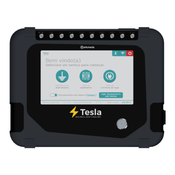
UNDERSTANDING THE DEVICE Next, the device will be demonstrated with the identification of its connectors and controls. FRONT VIEW Connectors Applied Part. On/Off Button. Touch Screen. - Page 11 UPPER VIEW Power cord with fuse 500V connector. holder.. Insulation resistance test. Air circulation. DUT Connector. LEFT SIDE VIEW Chassi’s cable XLR connector.
- Page 12 RIGHT SIDE VIEW Active air circulation. BACK VIEW Serial number identifi cation tag.
-
Page 13: Turning On The Device
TURNING ON THE DEVICE Press the “on/off” button to turn the device on. The device will perform internal communication tests and will then display the screen with the test options. -
Page 14: Bluetooth
BLUETOOTH The Bluetooth option is displayed in the upper right corner, indicating whether it is enabled or disabled. If it is disabled, an “X” will be displayed next to the symbol, and to enable it, just click on the Bluetooth icon. -
Page 15: Wifi
WIFI In the upper right corner, the Wi-Fi option is presented. Click on the Wi-Fi icon to access this function. A screen with available networks and a field for filling in the SSID and password of the desired network will be displayed. -
Page 16: Shutdown Button
Clicking on this option will display a message asking if you want to turn off the analyzer. By selecting “yes,” the device will turn off, and by selecting “no,” it will return to the home screen. TEST MODULES We show in this section each of the features of the Electrical Safety Analyzer, TESLA. -
Page 17: Ground Resistance Test
Class I devices. Ground Resistance Connection Connect as instructed: 1. Connect TESLA to the power grid. 2. Connect the power cord of the device under test to the DUT. 3. Connect the Chassis cable to the ground pin of the device under test. - Page 18 1. Disconnect the device from the DUT port 2. With the Chassis cable connected to Tesla, connect the banana pin to the ground pin of the DUT. 3. Start the measurement. If a resistance reading appears, repair...
-
Page 19: Insulation Resistance Test
2. Connect the power cord of the device under test to the DUT. 3. Connect the banana/banana connector to the 500V output of Tesla and the other end to the case of the device under test. With all connections made, start the test. - Page 20 In the “Insulation Test” option, we will have access to the Insulation Resistance measurement test. Click Start to begin measurement.. Warning When TESLA is activated, the test will release 500 VDC in the device under test. Avoid contact with connecting parts of the device. This test is performed if:...
-
Page 21: Leakage Current Test
LEAKAGE CURRENT TEST The Leakage Current Test is a procedure that aims to verify the value of leakage current to the ground from the ground pin of the device and its applied parts. This test is done directly and in reverse. In addition, it is possible to activate each channel of the applied parts and activate individually: Phase, Neutral, and Ground. - Page 22 Leakage Current Has on/off Perform the method switch? Alternative IEC 62353 Device isinsulated Perform the method from ground? Differential IEC 62353 Perform the method Perform the method Perform the method IEC 60601 to Direct IEC 62353 Differential IEC 62353 leakage current Device has applied parts type F (BF and CF)?
- Page 23 Leakage Current Connection to Ground Connect as instructed: 1. Connect TESLA to the power grid. 2. Connect the power cord of the device under test to the DUT. 3. Connect the Chassis cable to the ground pin of the device under test.
- Page 24 Settings Enable the “Grounded Case” option and perform Phase, Neutral, and Ground switching as per the standard. For the reverse test, click on the “Direct” option, and the link will be changed. If you want to go back to the “Direct” link, click on the option again.
- Page 25 Connect as instructed: 1. Connect TESLA to the power grid. 2. Connect the power cord of the device under test to the DUT. 3. Connect the applied parts to TESLA’s applied part connectors. With all connections made, start the test.
- Page 26 Settings Enable the connected applied parts, jointly or individually, and perform Phase, Neutral, and Ground switching as per the standard. For the reverse test, click on the “Direct” option, and the link will be changed. If you want to go back to the “Direct” link, click on the option again.
-
Page 27: Functional Current Test
The verification of the functional current of the tested device is performed by pressing the button “Turn on Device Under Tests.” When activating, the voltage is released to the DUT, and TESLA measures the functional current and apparent power of the device under test. -
Page 28: Software And Application
Just select the OS created by the App and enable the option to autofill all items or this item. A message will appear on the TESLA screen to make the connection and enable the automatic test. The test will start as defined in the checklist for the device in question by clicking Yes. -
Page 29: Problems And Solutions
REMOTE ACCESS If your device has a problem, TESLA has the option of remote access that allows a better understanding of the failure in the field and its necessary corrections, if applicable, in addition to new updates. In case of failure, please contact our Support Team. -
Page 30: Maintenance
This product is a calibration and performance test instrument. Any modification may alter its references and present dubious readings. Maintenance may only be made by personnel trained and qualified by Arkmeds. The manufacturer recommends annual preventive maintenance to verify calibration points, adjustments, and possible hardware and software updates. - Page 31 GROUND RESISTANCE Range 0.1 Ω to 10.0 Ω Tolerance ± 1% + 0.5 ohm INSULATION RESISTANCE TEST Range 0 MΩ to 200 MΩ (applied voltage - 500VDC) Tolerance ± 1% LEAKAGE CURRENT Range - Tolerance • 0μA - 500μA (DC to 1kHz - ± 1%) •...
-
Page 32: Faq
100 to 240V RMS Tolerance ± 5% POTÊNCIA APARENTE Range 0.1 VA to 1920 VA Tolerance ± 5% FA Q In case of doubts, problems, or suggestions, please contact the Arkmeds Customer Success Team at: https://www.arkmeds.com.us/support evolving people, companies, and markets.
Need help?
Do you have a question about the Tesla and is the answer not in the manual?
Questions and answers