Table of Contents
Advertisement
Quick Links
文件类型
文件编号
文件编号
ECR/PCN
版本
TCN
A1
/
ECR201320
A2
15100053
ECR201801
A3.0
07
发放部门
存档方式
制 订
2018.1.22
日 期
保密文件,知识产权归安保科技公司所有
密级:★★★★
技术文件
H-1.601.00070
6000S User Manual
参 考 资 料
修 订 记 录
更 改 内 容
首次发布
更新公司 Logo
更新地址及联系方式
生产部
□ 采购部
电子文档
纸文档
审 核
日 期
项目编号
打印要求
说明
质量部
□ 市场部
□ 其它:
批 准
2018.1.22
日 期
ABMOBAN0001(A1.0)
606
彩色
□
黑白
制 订
批准日期
苑振家
2014-09-03
苑振家
2015-10-22
□ 研发部
2018.1.22
Advertisement
Table of Contents

Related Manuals for Ambul D-Tiger 6000S

Summary of Contents for Ambul D-Tiger 6000S
- Page 1 密级:★★★★ ABMOBAN0001(A1.0) 文件类型 技术文件 项目编号 文件编号 H-1.601.00070 打印要求 彩色 □ 黑白 6000S User Manual 参 考 资 料 文件编号 说明 修 订 记 录 ECR/PCN 版本 更 改 内 容 制 订 批准日期 首次发布 苑振家 2014-09-03 ECR201320 更新公司 Logo 苑振家...
- Page 2 D-Tiger 6000S USER MANUAL Instructions and Safety Considerations of Ambulanc Transport Ventilator FILE NO.: H-1.601.00070 VERSION: A3.0 ISSUE DATE: 2018-01-22...
- Page 3 H-1.601.00070-A3.0 © COPYRIGHT AMBULANC (SHENZHEN) TECH.CO. ,LTD. 2017 ALL RIGHTS RESERVED Intellectual Property Statement AMBULANC (SHENZHEN) TECH.CO., LTD. (hereinafter called Ambulanc) owns the intellectual property rights to this Ambulanc product and this manual. This manual may refer to information protected by copyrights or patents and does not convey any license under the patent rights of Ambulanc, nor the rights of others.
- Page 4 H-1.601.00070-A3.0 Warranty THIS WARRANTY IS EXCLUSIVE AND IS IN LIEU OF ALL OTHER WARRANTIES, EXPRESSED OR IMPLIED, INCLUDING WARRANTIES OF MERCHANTABILITY OR FITNESS FOR ANY PARTICULAR PURPOSE. Exemptions Ambulanc's obligation or liability under this warranty does not include any transportation or irresistible natural disaster or other charges or liability for direct, indirect or consequential damages or delay resulting from the improper use or application of the product or the use of parts or accessories not approved by Ambulanc or repairs by people other than Ambulanc authorized personnel.
- Page 5 H-1.601.00070-A3.0 Product Information Product Name: Transport Ventilator Model: 6000S Manufacturer: Ambulanc (Shenzhen) Tech. Co., Ltd. Manufacturer address:3rd Floor, Block C, Building #5, Skyworth Innovation Industry Park, Tang Tou 1st Road, Shiyan Town , Baoan District, Shenzhen 518108, China. Warning This device is not intended for home using! Company Contact Manufacturer: Ambulanc (Shenzhen) Tech.
-
Page 6: Table Of Contents
H-1.601.00070-A3.0 Contents Overview ..........................1 Description ..........................4 2.1 Intended use ........................4 2.2 Applications ........................4 2.3 Users qualification ......................4 2.4 Ventilation function ......................5 2.5 Controlled ventilation (IPPV) ..................5 2.6 Assisted ventilation (Assist) ..................5 2.7 Manual operation mode ....................6 2.8 Patient ventilation Hose System ...................6 3. - Page 7 H-1.601.00070-A3.0 5.11 Battery management ....................23 6. Hygienic preparation ......................25 6.1 6000S ..........................25 6.2 Patient valve .......................25 6.3 Ventilation hose ......................25 6.4 Pressure gauge tube ....................26 6.5 Components and accessories ..................26 6.6 Fittings ........................26 6.7 Cleaning, disinfecting and sterilizing .................27 7. Functional checks .........................29 7.1 Intervals ........................29 7.2 Checking for leaks in the system ................30 7.3 Checking the patient valve ..................31...
-
Page 8: Overview
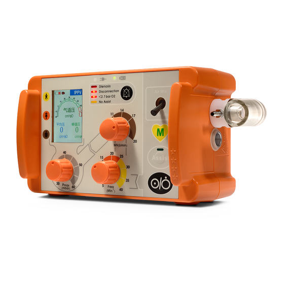
H-1.601.00070-A3.0 1. Overview 1. Pressure monitoring hose connection 2. Connection for ventilation hose 空气进口 3.Safety valve 9. Adapter 4. Air filter 8. DC interface 7. O inlet 6. Speaker 5. Rechargeable battery couldn’t replacement it; Maintenance 1. Pressure monitoring hose interface can be used for the machine connection maintenance, non-professional couldn’t... - Page 9 H-1.601.00070-A3.0 Control of 6000S 3. AC adapter indicators ligth 1. LED display 2. Alarm panel 4. Battery indicators light 5. Voice alarm mute key 6. Air Mix/No Air Mix switch 7. Minute volume regulator 8. Manual operation key 9. ON/OFF switch assisted ventilation 10.ON/Off button 机键...
- Page 10 H-1.601.00070-A3.0 Display of 6000S 1. Battery status indicators 2. Line operation indicators 3. Ventilation modes indicators 4. Measurement parameters display 5. Mean airway pressure 6. Peak airway pressure 1. Battery status indicators pressure, monitor the airway pressure within the set maximum pressure, Arc when battery is low display red to give a area filled with green, Paw and mbar alarm, rolling green bar when...
-
Page 11: Description
H-1.601.00070-A3.0 2. Description 2.1 Intended use The 6000S is an automatic oxygen respiration device(short-term ventilator) with additional inhalation facility.6000S can control and assist Patient whose weight is more than 15Kg, as well as non-invasive and invasive mechanical ventilation. 6000S must only be operated when it is security installed or when it is on approved carrying platforms. -
Page 12: Ventilation Function
H-1.601.00070-A3.0 2.4 Ventilation function 6000S operates within a pressure range of 2.7 to 6 bar and at a flow rate of not less than 70l/min O It has a built-in power pack. It uses high-pressure, medicinal-grade oxygen. An external pressure reducer brings this down to the required operating pressure. -
Page 13: Manual Operation Mode
H-1.601.00070-A3.0 With this function, the ventilation strokes of the device can be synchronized with the breathing in air from the surrounding atmosphere via the patient valve. If the patient does not trigger the device, an alarm is triggered. The patient continues to receive controlled ventilation. -
Page 14: Safety Instructions
H-1.601.00070-A3.0 3. Safety instructions For your own safety and that of your patients, please observe the following points. 3.1 General Always carry out a functional check before using the unit. (See "7. Function check"). Please read the directions for use carefully. They are an integral part of the ventilator and should be available for reference at all times. -
Page 15: Safe Using Of Oxygen
H-1.601.00070-A3.0 3.2 Safe Using of Oxygen Highly compressed oxygen can lead to spontaneous explosive reactions in combination with flammable substances (grease, oil, alcohol, disinfectants, etc,): Warning All screw connections and other components of the ventilator must be kept absolutely free of oil and grease. ... -
Page 16: Patient Ventilation Hose System
H-1.601.00070-A3.0 Make sure that the patient valve is not covered or its function impaired, e.g. by the patient's position. In the process of ventilation, it must be continuously observed patient and ventilator. 3.4 Patient Ventilation Hose System Warning Risk of injury. Only use the Patient Hose System if you are a qualified medical professional and have received training in respiration techniques. -
Page 17: Installation
H-1.601.00070-A3.0 4. Installation As a rule, 6000S only has to be installed for stationary use in rescue vehicles, helicopters or aircraft. In this case, fastening sets can be supplied as accessories. If 6000S is supplied complete on a stretcher board, or mounted on an Ambulanc Emergency Bag, then the device is ready for operation and no further installation work is required. -
Page 18: Ventilation Hose System
H-1.601.00070-A3.0 Caution Make sure that the patient is not connected up to the 6000S when you are establishing the gas supply. Otherwise, the automatic self-test of machine will lead to incorrect results. When doing this, hold the valve opening away from your body in such a way that any flying particles cannot injure yourself or other people. - Page 19 H-1.601.00070-A3.0 Φ30mm Convex cone Interface Outlet Φ15mm/20mm Coaxial Interface Intake Patients connector ( Connect to Φ15mm/20mm Coaxial Interface mask / intubations) Emergency air intake Non-standard interfaces Φ5mm Non-standard cylindrical Pressure measurement tube connecting point interfaces arning We strongly recommend to use the original Accessories supplied by Ambulanc only, malfunctions and a lack of biocompatibility may result if products from other manufacturers are used.
-
Page 20: Using The Ventilator
H-1.601.00070-A3.0 5. Using the ventilator 5.1 Switching on/ self test 1. Open the valve of the oxygen cylinder slowly. The pressure gauge will now show the pressure in the cylinder. 2. Calculate the remaining operating time (please refer to “5.9 Calculation the oxygen level/operating time”). Always change the cylinder in good time, e.g. -
Page 21: Selecting The Ventilation Settings
H-1.601.00070-A3.0 5.2 Selecting the ventilation settings The settings can be selected either before or after the 6000S is switchen on. We recommend selection before switching on, to prevent unnecessary waste of oxgen. Air Mix/No Air Mix In the case of a given indication, it is possible to ventilate using pure oxygen or using mixed air. -
Page 22: Selecting Ventilation Mode
H-1.601.00070-A3.0 Recommended maximum ventilation pressure Mask ventilation Intubations 20 mbar 45 mbar The values given in the table are recommendations. Deviating values are possible for certain indications. If the set level is reached, e.g. in cases where compliance is inadequate, 6000S sets off a stenosis alarm.(Note “Stenosis alarm”... -
Page 23: Performing Ventilation
H-1.601.00070-A3.0 Example of a ventilation curve in Assisted Ventilation mode: The patient furthermore has the option of performing a spontaneous breath via the patient valve between triggered ventilation strokes. In this case, the patient draws air for breathing from the ambient air. If the patient fails to trigger the device within the time window in two consecutive phases, i.e., is making no more breathing effort, the NO Assist alarm is triggered (note “4.9 Alarm signals”... -
Page 24: Monitoring Ventilation
H-1.601.00070-A3.0 NOTE: Use this model if patient can autonomous respiration. Intubations The patient will normally be intubated before the patient valve is connected to the tube. Set appropriate ventilation mode and related respiratory parameters fit for patients. Insert patient’s ventilation valve to the trachea intubations connector. During ventilation, please always observe the respiratory parameters on the screen. -
Page 25: Ending Ventilation
H-1.601.00070-A3.0 Displayed measurements During ventilation, the following parameters are shown on the display as numbers:: Image display the real-time airway pressure, monitor the airway pressure within the set maximum pressure, Arc area filled with green, Paw and mbar letters show green, more than set the maximum pressure Arc area filling red, Paw and mbar letter turn to red to give an... - Page 26 H-1.601.00070-A3.0 NO Assist: In Assisted Ventilation mode, patient fails to trigger within the time window in two consecutive phases. This equipment adopts the light alarm levels are high priority, once the alarm equipment handled in a timely manner. alarm sound Sound Light Light...
- Page 27 H-1.601.00070-A3.0 6000S briefly switches to expiration if the maximum ventilation pressure is exceeded, but the tries to continue inspiration in the same inspiration phase. If the maximum ventilation pressure is exceeded for a second time during the same inspiration phase, the unit finally switches to expiration and vents the patient tube system completely.
- Page 28 H-1.601.00070-A3.0 Canceling acoustic alarm The acoustic alarm can be temporarily cancelled by pressing alarm acknowledgement Stenosis: 120 seconds Disconnection: 120 seconds < 2, 7 bar: 120 seconds 120 seconds NO Assist: 120 seconds Even if audio response is enabled, no messages will be output for the periods stated. The visual alarm will continue to flash.
-
Page 29: Selecting Language For User Guidance
H-1.601.00070-A3.0 5.8 Selecting language for user guidance 6000 s did not shut down operation guide function. It meaning in any case, voice operation guide is opening. 6000 s did not shut down operation guide function. It meaning in any case, voice operation guide is opening. Voice guide with a variety of languages, please select the language as follows: 1. -
Page 30: Calculation Of Oxygen Content/Remaining Operating Time
H-1.601.00070-A3.0 gas supply” side. Check whether the O2 cylinder still contains sufficient oxygen and that the oxygen hose is not leaking, kinked or jammed. “Close oxygen cylinder” After switching off the ventilator, turn off the O2 cylinder or the external O2 supply. “Check ventilation system and Disconnection: a pressure rise of 3 mbar is not settings”... - Page 31 H-1.601.00070-A3.0 Battery Status indicators Battery status indicators displays in upper-right corner of the screen instructions to do all kinds of instructions are as follows: Indicators Instructions Battery full Battery not full The battery has been exhausted Lattice by small black arrows show the direction of non-stop flashing, indicating the battery is charging Attention!...
-
Page 32: Hygienic Preparation
H-1.601.00070-A3.0 6. Hygienic preparation After every use the 6000S and any accessories used must undergo hygienic preparation. Be sure to carry out a functional check after every hygienic preparation (see “7. Functional checks”). 6.1 6000S You can keep 6000S clean by simply wiping with disinfectant as described in section 6.6. -
Page 33: Pressure Gauge Tube
H-1.601.00070-A3.0 6.4 Pressure gauge tube To disinfect the pressure gauge tube of the ventilation hose, proceed as follows: Connect one end of the pressure gauge tube to a sterile disposable 20-ml syringe. Immerse the other end in the dilute disinfectant solution. Draw the disinfectant solution through the pressure gauge tube into the syringe until the latter is full. -
Page 34: Cleaning, Disinfecting And Sterilizing
H-1.601.00070-A3.0 If in exceptional cases you have no alternative but to disinfect by wiping, take particular care to prevent any fluid getting into the pressure reducer. 2. In addition to the risk of explosion, there also the risk of disinfectant getting into the patient’s respiratory tract with the oxygen and leading to injury. - Page 35 H-1.601.00070-A3.0 After disinfection, the pressure gauge hose must be rinsed with distilled water at least 8 times using the same principle. You can support the subsequent drying process with medical compressed air or medical oxygen. Caution Then allow the components to dry thoroughly. If any water is left in the patient valve or the pressure gauge hose of the ventilation hose, the unit may not function correctly.
-
Page 36: Functional Checks
H-1.601.00070-A3.0 7. Functional checks Before each use, after each dismantling and reassembly, and at the very least every 6 months, the user must carry out functional checks on the ventilator. NOTE: Before carrying out the functional check on 6000S, you must connect the ventilation hose and the patient valve. -
Page 37: Checking For Leaks In The System
H-1.601.00070-A3.0 7.2 Checking for leaks in the system 1. Open the valve of the oxygen cylinder slowly. You can now read the pressure in the cylinder from the gauge on the pressure reducer. For example, a reading of 200 bars means that the cylinder is full, whereas 100 bars mean it is half full. NOTE: Always change the cylinder in good time, e.g. -
Page 38: Checking The Patient Valve
H-1.601.00070-A3.0 7.3 Checking the patient valve One-way valve membrane base One-way valve membrane One-way valve membrane Disassemble the patient valve. Carry out a visual check of all components for cracks or other physical damage. The One-way valve membrane must be replaced if it is crinkled, sticky or misshapen. - Page 39 H-1.601.00070-A3.0 Stenosis 1. Open the oxygen cylinder. 2. Remove the tube or the ventilation mask from the patient valve. 3. Switch on 6000S. 4. Switch the mask/tube switch 1 to mask ventilation mode. 5. Keep the ventilation connector on the patient valve closed with the flat of your hand during two successive inspiration phases.
-
Page 40: Trouble Shooting
H-1.601.00070-A3.0 8. Trouble shooting Fault Cause Remedy 6000S defective. Arrange for repair. Replace battery in battery compartment. 6000S will not switch If ventilator still refuses to switch Battery failing. on, have internal auxiliary battery replaced by manufacturer or authorized specialists. Airways obstructed. - Page 41 H-1.601.00070-A3.0 Patient does not trigger Adapt ventilation frequency to suit device within time window patient Patient does not trigger Continue ventilation in Controlled Alarm No Assist device at all Ventilation mode Valve membranes in spontaneous breathing arm Insert new valve membrane detective or missing Visual alarms flashing, but no acoustic alarm...
-
Page 42: Servicing
H-1.601.00070-A3.0 9. Servicing 9.1 Intervals NOTE: Always remember to carry out a technical safety check on the ventilator after every repair. 6000S must undergo a technical safety check and servicing at regular intervals. After each using: Cleaning and disinfecting reusable ventilation hose and patient valve according to the instruction in Chapter VI. -
Page 43: Battery
H-1.601.00070-A3.0 9.3 Battery 6000S is equipped with one battery: The battery (Li-ion battery7.4 V) is designed for power supply. It can be changed by the operator. In room temperature environment the full power battery's working time is up to 10 hours. -
Page 44: Storage
H-1.601.00070-A3.0 remove. 2. To pull old filter out by forceps. 3. Wipe the filter cartridges with medical cotton ball (moistened with alcohol). 4. Use alcohol to clean and to disinfect the filter compartment cover and let it dry 5. Install the new filter into filter cartridges with forceps. 6. -
Page 45: Product And Accessories
H-1.601.00070-A3.0 10. Product and accessories 10.1 Standard product Parts Parts No. QTY(PCS) Note 6000S Main Unit 4.606.00001 Reusable Ventilation Hose 5.000.00235 Patient Valve 2.602.00019 Mask Hook 5.001.00033 Reusable Mask (4#) 5.001.00035 Adult, Middle Silicone Headgear (Adult) 5.001.00037 Power Adapter (12V) 1.119.00003 AC Power Cord 1.124.00001... -
Page 46: Parts List Of Ventilator Bag I
H-1.601.00070-A3.0 Sputum Aspirator 4.109.00001 Transparent Tube for 5.000.00164 Sputum Suction Fitted on the wall of Wall Bracket 2.601.00022 Ambulance Intubation Tube Adult,7#) 5.001.00049 One-way Valve Membrane 1.402.00030 Fittings of Patient Valve Fittings of Patient Valve One-way Valve Base 1.402.00054 Fittings of Main Unit Filter 1.503.00029 Open Mouth tongs... - Page 47 H-1.601.00070-A3.0 Degree of Protection against Electric Shock Degree of protection against IPX4 Ingress of Liquids Degree of Protection against Ordinary equipment, without protection against Hazards of Explosion explosion; not for use with flammable anesthetic Mode of Operation: Continuous running equipment Dimensions W×H×D in mm 240×120×100mm include connectors Weight...
- Page 48 H-1.601.00070-A3.0 -Supply pressure At least 2.7bar -Drawn flow At least 70 l/min Oxygen(ATPD) Optimal gas supply: -Supply pressure At least 4.5bar -Drawn flow At least 100 l/min Oxygen(ATPD) Non-recommended gas supply: -Supply pressure Less than 2.7bar -Drawn flow Less than 80 l/min Oxygen(ATPD) Insp-exp.
-
Page 49: Product Structure Diagram
H-1.601.00070-A3.0 11.2 Product structure diagram Air inlet 6000S Host Filter Air-oxygen mixture Safety valve Reducer valve Press gas inlet and injector Patient valve Pressure sensor Controlling Electronic analysis unit unit Alarm display unit Patient 11.3 O content when using Air Mix The following diagram shows the oxygen concentration prevailing at various conuter-pressures and minute volumes when Air Mix is switched on. -
Page 50: Warranty
H-1.601.00070-A3.0 12. Warranty Ambulanc provides one year warranty from the date of purchasing and lifelong maintenance. Suggested Product’s life:Three years. Claims against the warranty can be made only when accompanied by the sales receipt, which must show salesperson and date of purchase. ... -
Page 51: Storage And Transportation
H-1.601.00070-A3.0 13. Storage and transportation Packaged product can be transported by truck, air or railway. During the transportation, should avoid shock, severe vibration and moisture. Transport temperature is -40 ℃ ~ +50 ℃, relative humidity should be less than 95%. Storage temperature -40 - 50℃... -
Page 52: Electromagnetic Capability
H-1.601.00070-A3.0 14. Electromagnetic Capability GUIDANCE AND DECLARATION - ELECTROMAGNETIC EMISSION The 6000S is intended for use in the electromagnetic environment specified below. The customer or the user of the device should assure that it is used in such an environment. ELECTROMAGNETIC ENVIRONMENT - EMISSIONS TEST COMPLIANCE... - Page 53 H-1.601.00070-A3.0 environment. ±1 kV ±1 kV differential Surge IEC differential mode ± 2 kV 61000-4-5 mode ± 2 kV common mode common mode Power frequency magnetic fields should Power frequency be at levels (50Hz/60Hz) 3A/m 3A/m characteristic of a magnetic field typical location in a IEC61000-4-8 typical commercial or...
- Page 54 H-1.601.00070-A3.0 GUIDANCE AND DECLARATION - ELECTROMAGNETIC IMMUNITY The6000S transport ventilator is intended for use in the electromagnetic environment specified below. The customer or the user of the device should assure that it is used in such an environment. COMPLIA IEC60601 TEST IMMUNITY ELECTROMAGNETIC TEST...
- Page 55 H-1.601.00070-A3.0 the6000S transport ventilator b Over the frequency range 150 kHz to 80 MHz, field strengths should be less than 3 V/ Recommended separation distances between portable and mobile RF communications equipment and the6000S transport ventilator. The6000S transport ventilator is intended for use in an electromagnetic environment in which radiated RF disturbances are controlled.
Need help?
Do you have a question about the D-Tiger 6000S and is the answer not in the manual?
Questions and answers