Table of Contents
Advertisement
Quick Links
文件类型
文件编号
文件编号
ECR/PCN
版本
TCN
A1.0
ECR20171163
A2.0
ECR20180118
A3.0
ECR20190207
A4.0
ECR20200407
A5.0
ECR20200609
B1.0
ECR20201119
B2.0
ECR20210102
B3.0
ECR20210311
发放部门
存档方式
制 订
日 期
2021.03.25
保密文件,知识产权归安保科技公司所有
密级:★
技术文件
H-1.601.00137
609 用户使用说明书(英文)
新增
FIGURE 43
1) 更新 11.8 节的"
2)
更新 2.1、2.2 关于设备预期用途的说明。
新增第 16 章。
修改 2.1 关于设备预期用途的说明
优化呼吸模式介绍。
根据 ISO10651-3 标准新增 3.6 参数关联;
警优先级说明等
修改 2.8.3 和 2.8.4 描述
封面增加 CE0123 标示
生产部
采购部
电子文档
审 核
日 期
项目编号
打印要求
参 考 资 料
说明
修 订 记 录
更 改 内 容
"图
修改地址信息、增加报
品质部
□ 市场部
纸文档
□ 其它:
2021.03.25
ABMOBAN0001(A1.0)
609
彩色
□
制 订
批准日期
胡国权
2017.12.20
胡国权
2018.01.28
施丽迪
2019.02.28
2020.05.08
陈德伟
罗妙
2020.07.02
谢荣锋
2020.11.02
陈德伟
2021.01.22
谢荣锋
研发系统
批 准
日 期
2021.03.25
黑白
Advertisement
Table of Contents

Related Manuals for Ambul T5

Summary of Contents for Ambul T5
- Page 1 密级:★ ABMOBAN0001(A1.0) 文件类型 技术文件 项目编号 文件编号 H-1.601.00137 打印要求 彩色 □ 黑白 609 用户使用说明书(英文) 参 考 资 料 文件编号 说明 修 订 记 录 ECR/PCN 版本 更 改 内 容 制 订 批准日期 A1.0 ECR20171163 新增 胡国权 2017.12.20 FIGURE 43 1)...
- Page 3 blank page...
-
Page 4: Table Of Contents
User Qualification ......................8 The main composition of ....................8 Main Unit ........................8 Patient Respiratory Hose and Accessories ..............9 T5 Main Unit instruction ....................9 3 Interface description ........................14 Composition of main interface ..................14 Main menu instruction ....................15 Alarm Message ...................... - Page 5 Recommended isolation distance ................74 12.5 Information on T5 Patient's Physiological ..............75 12.6 Basic EMC Properties of T5 Emergency ..............76 13 Warranty ............................. 77 14 Classification of Toxic/Harmful Substances ..............78 15 Storage and Transport ......................80 16 Transient operating conditions .................... 81...
- Page 6 H-1.601. 00137-B3.0 Product Information Thank you for purchasing T5 Emergency Ventilator. Before using the equipment, please read this manual carefully and understand the information contained in it so as to operate it properly. Keep this manual properly in any accessible place.
- Page 7 H-1.601. 00137-B3.0 Intellectual Property Right © 2017 Ambulanc (Shenzhen) Technology Co. Ltd. All rights reserved This product and its operating manual are the intellectual property of Ambulanc (Shenzhen) Technology Co. Ltd., including but not limited to patent right, trademark right and copyright. Ambulanc has the final right to interpret this manual.
- Page 8 H-1.601. 00137-B3.0 Statement Ambulanc reserves the right to modify this manual without prior notice. Ambulanc reserves the right to change related technology without prior notice. Ambulanc reserves the right to alter product specification without prior notice. Ambulanc makes no warranty in any form concerning this manual, including (but not limited to) guarantee for implied marketability and adaptability for a specific purpose.
- Page 9 H-1.601. 00137-B3.0 Maintenance Service Scope of Charge-Free Service: • Charge-free service is provided for any equipment in the range of Ambulanc's warranty terms. Scope of Paid Service: • Paid service is provided for any equipment beyond the range of Ambulanc's warranty terms. As well as in one of the following cases even during the warranty period: •...
- Page 10 H-1.601. 00137-B3.0 Return Return Procedure Any return as necessary shall comply with the following procedure: • Acquire right of return: Contact Ambulanc's customer service, and provide the product ID labeled on external packaging of the instrument, which must be legible for return approval. Indicate product model and describe the reason for return.
- Page 11 H-1.601. 00137-B3.0 the operator's fault or any exceptional condition. 9. This manual contains warnings for foreseeable potential hazards. User shall keep watch at any time for any hazard not stated in the manual. Ambulanc takes no responsibility for damage or loss resulted from negligence or failure to observe the preventive measures stated in this manual.
- Page 12 H-1.601. 00137-B3.0 blank page...
-
Page 13: Equipment Description
Improper use of it may cause serious injury to body. • 【Do not leave T5 in ventilation】 Do not leave a patient or respirator in ventilation to respond in time to any emergency (such as patient's worsening state of an illness or machine fault) to minimize the patient's injury. - Page 14 If not necessary (when battery capacity is lower than 20% or T5 is used in an uninterrupted way for a long time), please do not use any external power supply;...
-
Page 15: Safe Use Of Oxygen
H-1.601. 00137-B3.0 Safe Use of Oxygen Warning: • High-pressure oxygen and combustible (lubricating grease, engine oil, alcohol, etc.) may give rise to an explosion when they meet each other. • Supply of oxygen in high concentration to a patient for a long time may generate toxic effect. -
Page 16: Ventilation/Operation
H-1.601. 00137-B3.0 Ventilation/Operation • During ventilation, uninterrupted observation of both the patient and respiratory equipment must be performed. • Prolonged breathing through respirator may result in atrophy of patient's respiratory muscles. • Lengthy ventilation may cause patient's respiratory tract dry. Make sure sufficient natural air is available for adjustment of respiration. -
Page 17: Accessories/Spare Parts
Battery Warning: 【Low battery】 When T5 alarms in low battery, please make any of the following operations: • Replace battery by fully charged battery. • Connect T5 with external T5 power supply. -
Page 18: Symbols That
H-1.601. 00137-B3.0 Symbols that Description ICONS and symbols SYMBOL DESCRIPTION SYMBOL DESCRIPTION Refer to the document Refer to the document attached for more details attached/manual Date of production BF type applications Waterproof level Do not reject into dustbin Adapter off Non-ionizing radiation Power supply by adapter Main Unit Switch... -
Page 19: Equipment Description
The T5 ventilator is intended to provide continuous ventilation for patients who require invasive or non-invasive respiratory support (Infants, children, adults), with a tidal volume greater than 50ml. The T5 ventilator is intended for use in out-of-hospital emergency treatment (first aid treatment on the... -
Page 20: User Qualification
• Provided with proper medical training in and technical guidance on respiration equipment. • Provided with training in clinical application with T5 by Shenzhen Amoul Technology Limited. • Improper operation of the equipment may cause serious injury to persons (the operator and patient). -
Page 21: Patient Respiratory Hose And Accessories
• Patient breathing valve: furnished with power-controlled PEEP valve structure for high-precision control of positive end-expiratory pressure (PEEP) and continuous positive airway pressure (CPAP). T5 Main Unit instruction 2.8.1 Main Unit-Front View FIGURE 1 Main Unit(Front View) Page 9 of 81... - Page 22 H-1.601. 00137-B3.0 PARTS DESCRIPTION 1 Warning LED When it alarms, it displays red and yellow flicker, signaling different alarm priority levels. Red=top priority, yellow=intermediate priority, off=no alarm. 2 Start/Shut Down button Press it to start. , Long press it for 3 seconds to shut down the equipment.
- Page 23 9 Indicator of external The indicator will be normally on when power supply T5 connects to power adapter. Tips: When the respirator is switched from external power supply to internal power supply, the respirator is still normally working.
- Page 24 H-1.601. 00137-B3.0 2.8.3 Main Unit-Left View FIGURE 3 Main Unit(Left View) PARTS DESCRIPTION 1 Speaker For acoustic indication or alarm. 2 USB port Covered with a rubber cap, and used for software maintenance and upgrade. 3 DC port Covered with a rubber cap, and used for connection of power adapter or used for DC power supply on ambulance or helicopter.
- Page 25 H-1.601. 00137-B3.0 2.8.4 Wain Unit-Right View FIGURE 4 Main Unit(Right View) PARTS DESCRIPTION 1 O2 source interface For connection to O2 source. 2 pressure measurement Used for measurement of airway pressure port 3 PEEP air supply port For connection of white hose in respiration hose loop.
-
Page 26: Interface Description
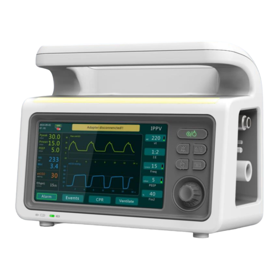
H-1.601. 00137-B3.0 Interface description Composition of main interface Adapter disconnencted!! tidal volume Freq PEEP Fio2 Alarm Events Ventilate FIGURE 5 Main interface PARTS DESCRIPTION 1 Time/date For real-time display of current time and date. 2 Battery state battery level or recharging state. 3 Adapter state For real-time indication of current power adapter status... -
Page 27: Main Menu Instruction
H-1.601. 00137-B3.0 parameter setting value for current mode by using the navigation knob. 9 Ventilate Use it to access Ventilate. 10 CPR For real-time display of current CPR function status. 11 Logs Use it to access system logs. 12 Alarm limits Use it to access alarm limits. - Page 28 H-1.601. 00137-B3.0 2 Alarm Set alarm volume and way. 3 System Set screen brightness, unit, desktop style, waveform style, voice, and ETCO2. 4 Time Set system time of equipment 5 Calibration Calibrate equipment's air proportion valve, oxygen proportion valve and PEEP proportion valve.
- Page 29 H-1.601. 00137-B3.0 3.2.2 Setting Alarm Volume In the main menu interface, select < Alarm > soft button and enter the alarm setting interface(As shown below). Adapter disconnencted!! tidal volume Freq PEEP Fio2 Alarm Events Ventilate FIGURE 8 Alarm PARTS DESCRIPTION 1 Volume By default three levels are available.
- Page 30 H-1.601. 00137-B3.0 FIGURE 9 System PARTS DESCRIPTION 1 Luminance By default two levels are available. The available options are: Level 1, Level 2, and Level 3. 2 Pressure unit The default unit is mbar. The available options are mbar, hPa, and cmH2O. 3 Desktop style The default style is Dark Green.
- Page 31 H-1.601. 00137-B3.0 3.2.4 Time setting In the main menu interface, select < Time > soft button to enter the time interface(As shown below). Adapter disconnencted!! tidal volume Freq PEEP Fio2 Alarm Events Ventilate FIGURE 10 Time 3.2.5 Calibration In the main menu interface, select <Calibration> soft button to enter calibration interface to calibrate air proportion valve, oxygen proportion valve and PEEP proportion valve (as shown in the following figure).
-
Page 32: Alarm Message
H-1.601. 00137-B3.0 3.2.6 About Host In the main menu interface, select <About host> soft button to view software version (as shown in the following figure). Adapter disconnencted!! tidal volume Freq PEEP Fio2 Alarm Events Ventilate FIGURE 12 About Host Alarm Message Press the alarm tips button in the main interface and it will display alarm information in the top priority. - Page 33 H-1.601. 00137-B3.0 multiple types of alarm. In case of any abnormality, medical workers will be effectively reminded of handling the abnormality to avoid any possible accident. The following describes the alarm function in detail: • priority: Type Voice alarm Remark The form of High-pri The alarm...
- Page 34 H-1.601. 00137-B3.0 High Minute ventilation is High minute Physiological level above upper ventilation alarm alarm threshold High Minute ventilation is Low minute Physiological level below lower ventilation alarm alarm threshold High EtCO2 is above upper Physiological High EtCO2 level threshold alarm alarm High...
- Page 35 H-1.601. 00137-B3.0 Medium level than 20% alarm alarm Adapter Medium The power adapter is Technical disconnecte level disconnected alarm alarm • Voice alarm: In actual sound alarms, either voice alarm or buzzer alarm can be selected. Voice prompt Meaning Level High No gas supply No gas supply pressure...
- Page 36 H-1.601. 00137-B3.0 alarm Battery level is too low. High Please replace the battery Battery level is too level Battery level is too alarm Check the gas supply condition to eliminate Insufficient gas Medium insufficiency of gas supply supply pressure level alarm pressure Medium High Vt...
-
Page 37: Review Events
H-1.601. 00137-B3.0 alarm message Blinking prompts will be given; el alarms with the highest frequency: for "beep beep beep" coexist priority; the 2s/time alarms, alarms will be alarm interface given according to the shows all alarm medium priority messages "beep beep beep" alarm type The prompt zone The red light... -
Page 38: Setting Of Alarm Limits
H-1.601. 00137-B3.0 Adapter disconnencted!! Events tidal volume Freq PEEP Fio2 Alarm Events Ventilate FIGURE 14 Events Up to 50 items of log message can be stored in the system. The older Events will be overwritten by the newer ones. In reviewing logs, pay attention to the following: •... -
Page 39: Ventilation Mode Parameter Linkage Relationship
H-1.601. 00137-B3.0 Adapter disconnencted!! tidal volume Freq PEEP Fio2 Alarm Events Ventilate FIGURE 15 Alarm PARTS PARTS 1 Upper airway pressure limit 6 Suffocation duration 2 Lower airway pressure limit 7 Upper tidal volume limit 3 Upper ventilation rate (per min.) 8 Lower tidal volume limit limit 4 Lower ventilation rate (per min.) - Page 40 H-1.601. 00137-B3.0 Tplat Finsp Vt= (Finsp*1000/60)*(Tinsp-Tinsp*Tplat) Te:Expiration Tinsp:Te = I :E Tinsp, Te, time Tinsp + Te = 60/Freq Finsp t Freq: Respiratory Vt= (Finsp*1000/60)*(Tinsp-Tinsp*Tplat) rate Tinsp:Te = I:E Tinsp, Te, Freq Tinsp + Te = 60/Freq Finsp t Vt= Finsp*1000/60)*(Tinsp-Tinsp*Tplat) When the triggering mode is pressure Trigger Trigger...
-
Page 41: Installation
In such case, we will supply a specific mounting bracket as an accessory. If T5 is supplied by being fixed completely onto a stretcher or packed in a first-aid package as an assembly, this equipment is well ready for use without mounting. -
Page 42: Connection Of Oxygen Cylinder
2. Connect reducing valve to port of the cylinder. Tighten the nut by hand. 3. Screw the pressure hose with 9/16-18UNF connecting nut into the outlet of reducing valve. 4. Connect the other end of the pressure hose to the air source port on T5. Patient Respiratory Hose Assembly and Its Connection T5 provides a reusable or disposable respiration management assembly. - Page 43 H-1.601. 00137-B3.0 in accordance with the following method. 2. Connect the rubber hose of patient value to pressure monitoring port on the main unit. 3. Connect the pu hose of patient valve to PEEP port on the main unit. 4. Connect breathing hose to the fresh gas intake. Be sure not to bend any connected air hose.
-
Page 44: Patient Breathing Valve
H-1.601. 00137-B3.0 Warning: Handle breathing hose, PU hose and rubber hose by holding ends of them to prevent any damage to or break of them. Any disposal hose assembly shall be disposed after being used. Patient Breathing Valve FIGURE 18 Patient Breathing Valve PARTS DESCRIPTION 1 PEEP air source port... - Page 45 H-1.601. 00137-B3.0 not be blocked. 5 Airway pressure Connect to pressure measuring port on measuring port main unit. Warning: The manufacturer Ambulanc (Shenzhen) Technology Co. Ltd. shall not be liable for any product performance problem resulting from use of respiratory hose assembly provided by any other manufacturer.
-
Page 46: Ventilation Operation
H-1.601. 00137-B3.0 Ventilation Operation Calibration of Touch Screen For the initial operation, the system will automatically enter touch screen calibration. User can click the touch points to finish calibration of the first (at the lower left corner) and the second (at the upper right corner) points, and then click a third point at any position of the screen to complete the calibration procedure (As shown below). -
Page 47: Startup-Self-Checking
50 bar. 3. Press down Start/Shut Down button to start T5. At this moment a progress bar indication self-checking is displayed on the screen. Upon end of the bar, the main interface appears, and voice prompts are given by the system, such as "open oxygen cylinder", "select respiration mode"... -
Page 48: Select Ventilation Mode
H-1.601. 00137-B3.0 FIGURE 23 Error code 5. It indicates that the main unit operates normally when no error message is displayed on the main interface. At this moment the respirator will not execute any ventilation mode or parameter, but pop up a Select Emergency Ventilation Mode dialog for your selection. -
Page 49: Main Ventilation Parameters Setting
H-1.601. 00137-B3.0 FIGURE 24 Ventilation Mode PARTS PARTS 1 V-A/C Mode 6 P-SIMV Mode 2 IPPV Mode 7 CPAP Mode 3 V-SIMV Mode 8 Manual Mode or HFNC Mode 4 PCV Mode 9 CPR Mode 5 P-A/C Mode Main Ventilation Parameters Setting For convenience of operation and review, 5 major ventilation parameters are provided at the right side of the main interface (As shown below). -
Page 50: Details On Ventilation Modes
In other word, consecutive respiration support is provided for breathless patient and each respiration is mandatory. T5 operates in volume-controlled IPPV, where air in preset tidal volume is conveyed to the patient at a constant flow rate and preset... - Page 51 H-1.601. 00137-B3.0 FIGURE 26 IPPV • In PCV (Pressure Controlled Ventilation), airway pressure and inspiration duration are preset. After inspiration is started, air flow rate is raised quickly to the preset pressure level and then slowed down by the feedback system and maintained at the preset pressure till end of inspiration, and then expiration is started.
- Page 52 H-1.601. 00137-B3.0 inspired air flow rate) are completely controlled by respirator, which supplies all respiratory power. CV is classified into Volume Controlled Ventilation (VCV) and Pressure Controlled Ventilation (PCV). • In AV (Assisted Ventilation), which is activated by decrease of airway pressure (pressure trigger) or change in flow rate (flow rate trigger), the respirator conveys air to the patient at preset tidal volume (or Inspiratory pressure), frequency, inspiration duration and expiration duration.
- Page 53 H-1.601. 00137-B3.0 • P-A/CV P-A/CV (Pressure Assisted/Controlled Ventilation) is based on VCV. Synchronous trigger is enabled in expiration stage. When the pressure reaches activation pressure, respirator provides one push of PCV at fixed Inspiratory pressure in advance. A typical pressure waveform of P-A/CV is shown below: FIGURE 29 P-A/CV Sign means a deep inhalation at two times of tidal volume based on IPPV once every certain times, which is suitable for patient in long-term need of...
- Page 54 A typical pressure waveform of P-SIMV is shown below: FIGURE 31 P-SIMV Note: the activation mode in T5 ventilator is pressure activation mode. 5.5.4 CPAP For purpose of CPAP (Continuous Positive Airway Pressure), the ventilator is...
-
Page 55: Execution Of Ventilation
H-1.601. 00137-B3.0 a proper pressure level to maintain positive pressure within the airway throughout the respiratory cycle. CPAP provides only a certain constant pressure support, not assistant ventilation function. Patient's respiratory patterns including frequency, amplitude, flow rate and tidal volume are all controlled by himself/herself. Therefore, any patient to whom CPAP is applied must have normal function to drive his/her respiratory center and sufficient capacity of spontaneous breathing. - Page 56 H-1.601. 00137-B3.0 FIGURE 33 Intubation 5.6.2 Respiratory mask 1. Connect respiratory mask to patient breathing valve. 2. Place respiratory mask onto patient's nose and mouth. 3. Keep patient's head backwards and make the mask worn closely against the face. 4. Before wearing the mask, keep patient's respiratory tract unblocked. FIGURE 34 Respiratory mask Page 44 of 81...
-
Page 57: Monitoring Of Respiration
H-1.601. 00137-B3.0 Monitoring of Respiration 5.7.1 Real-Time Ventilation Parameters Adapter disconnencted!! tidal volume Freq PEEP Fio2 Events Alarm Ventilate FIGURE 35 Ventilation Parameters PARTS PARTS 1 Airway Peak Pressure 5 Ventilation rate 2 Average airway pressure 6 Concentration of carbon dioxide 3 PEEP 7 Respiration frequency... -
Page 58: Cpr Ventilation
H-1.601. 00137-B3.0 5.7.2 Waveform Diagram FIGURE 36 Waveform Diagram PARTS PARTS 1 Designation unit 3 Time scale 2 Pressure scale CPR Ventilation CPR (Cardiopulmonary Resuscitation) is a procedure used for first-aid treatment. CPR is a first-aid ventilation mode for blood circulation or respiratory arrest and intended to maintain supply to patient's organism and assistance with emission of CO2 from the body. - Page 59 H-1.601. 00137-B3.0 time of 1s I/E of 1:2, and inspiration Infants 100ml time of 1s Adapter disconnencted!! Choose patient type tidal volume Freq PEEP Fio2 Alarm Events Ventilate FIGURE 37 Select patient type • Secondly: As shown below, access operation mode selection window with voice prompt "please select operation mode".
-
Page 60: End Ventilation
H-1.601. 00137-B3.0 Adapter disconnencted!! tidal volume Freq PEEP Fio2 Alarm Events Ventilate FIGURE 38 Selection of Operating Mode • Thirdly: As shown below, start CPR function - first voice prompt "press for 5 cm or more", then "start pressing", and finally alternative voice prompt "... -
Page 61: Calculation Of Storage Capacity/Operation
H-1.601. 00137-B3.0 Attention: Do not use up any oxygen cylinder. Make sure there is residual pressure inside the cylinder when it is returned so as to prevent entry of wet air into it and corrosion caused thereby. 1. Check the pressure meter on the reducing valve to be aware of the oxygen storage in it. -
Page 62: Alternative Breathing Apparatus
1. Remove the patient breathing valve off the cannula or mask. 2. Connect respiratory bag and then perform manual respiration. • Failure of Oxygen In case of failure of oxygen source for T5, the patient can inhale air through patient breathing valve. 5.12 Battery Management T5 is equipped with a built-in chargeable battery whose working time must not be shorter than 5 hours in standard state. - Page 63 H-1.601. 00137-B3.0 A floating battery level indicates that the battery is being recharged. If battery indicator LED turns on, it indicates that the battery is connected; the LED going off indicates that the battery is disconnected or run out of; the LED which keeps flashing means that the battery is being recharged.
-
Page 64: Sanitization
H-1.601. 00137-B3.0 Sanitization T5 and its accessories must be sanitized each time after use to keep them in good condition and avoid cross infection. Each time after sanitation, perform functional inspection (refer to Section 7 - Functional Inspection). T5 Main Unit Scrub and clean the host simply by soft cloth wet by common water-soluble sanitizer. -
Page 65: Valve Fittings
Where disinfection is absolutely necessary, please wipe the reducing valve and the oxygen cylinder with a clean soft cloth, which is dry or slightly soaked with clean water. Sanitization Methods Sanitize T5 main unit and its accessories by using the methods as stated below: Part Cleaning... -
Page 66: Functional Inspection
User must perform a functional inspection on the equipment prior to use and after disassembly, or once every six months. Tips: When performing functional inspection on T5, the respiratory hose and patient breathing valve must be connected. In case that any malfunction or deviation to any set value is found in functional inspection, the ventilator shall not be used until such malfunction is remove in accordance with Section 8 - Trouble Shooting. -
Page 67: Inspect System Air-Tightness
3. Discharge the system pressure by shutting off the oxygen cylinder. Start T5 till the reading on cylinder is "0"; and then shut down T5. 4. In case of leakage, replace the damaged component. - Page 68 H-1.601. 00137-B3.0 Warning: In case of any problem during inspection, stop using it for the patient! 1. Connect power supply and air supply, and check whether the power supply and air supply operate normally. 2. Start the machine to make it perform self-checking, to mainly inspect whether all sensors operate normally.
- Page 69 During self-checking upon startup, low battery level alarm function can be checked. When oxygen cylinder is opened, If T5 is started and operates normally and no alarm is triggered, it indicates that the battery is at sufficient voltage level.
-
Page 70: Trouble Shooting
Stop using the machine in problem to avoid any potential injury. Technical Failure Failure Cause Solution T5 fails to start T5 malfunctions Contact the manufacturer or your dealer for repair Battery is exhausted Recharge battery... -
Page 71: System Alarm
H-1.601. 00137-B3.0 Airway is blocked Examine the patient's condition Respiratory hose is Locate respiratory located improperly hose properly Pmax is set to a too Set Pmax to a proper low value value Respiratory hose is Check patient's wound position and make correction as necessary System Alarm Message... -
Page 72: Abnormal Power Failure Alarm
Abnormal power failure alarm T5 has the function of shutdown alarm caused by abnormal power failure of the system The alarm triggers a buzzer alarm when the host is shut down due to abnormal power failure, and the alarm duration is not less than 15 seconds;... -
Page 73: Maintenance
H-1.601. 00137-B3.0 Maintenance Routine inspection Safety inspection shall be performed after each overhaul, and T5 shall undergo safety inspection and maintenance regularly. After each use: Clean and disinfect reusable respiratory hose and patient breathing valve in accordance with relevant instructions in Section 6. -
Page 74: Accessories
12. Avoid using the battery in strong sunlight. Tips: The battery which T5 is furnished with is subject to no memory effect. Thus you can recharge it whenever possible without impairment of its service life, provided that a battery has its inherent lifespan , such as 2 years or 300 recharging times. -
Page 75: Storage
Storage If T5 is left idle for a long time, it is recommended to take the following measures: 1. Clean and disinfect the equipment (refer to Section 6 - Sanitization). -
Page 76: T5 Supplies Configuration
H-1.601. 00137-B3.0 10 T5 Supplies Configuration 10.1 Standard Components Name Material coding Unit Remark T5 Main Unit 2.609.00002 English Reusable respiratory 2.609.00018 hose Big hanger for rubber 5.001.00033 mask Reusable rubber mask 5.001.00035 (4#) Rubber headgear (for 5.001.00037 adults) Power adapter 2.609.00021... -
Page 77: Ventilation Mode Configuration List
H-1.601. 00137-B3.0 Splint 5.000.00168 Bearing system 2.609.00015 Caution: The specific configuration shall be subject to the packing list. 10.3 Ventilation Mode Configuration List Ventilation Mode Options IPPV ● V-A/C ● V-SIMV ● ● P-A/C ● P-SIMV ● CPAP ● Other Functions Options Manual ●... -
Page 78: Technical Parameters
H-1.601. 00137-B3.0 11 Technical Parameters 11.1 Medical Devices Management Category Medical Devices Management Category Category Class-III 11.2 Physical Specifications Machine size size length:250mm width:200mm height:127mm Weight 3.4 kg Display screen Types of TFT color screen size 7” Resolution 800 x 480 pixels Features With resistor type touch screen control 11.3 Environmental specifications... -
Page 79: Ventilation Mode
H-1.601. 00137-B3.0 11.5 Ventilation mode Ventilation mode Volume-control V-A/C、V-SIMV、IPPV mode Pressure-control P-A/C、P-SIMV、CPAP、PCV mode Other mode CPR、Manual、HFNC 11.6 Supply specifications Supply specifications Air supply Medical oxygen Air supply pressure 2.7~6.0 bar 11.7 Ventilator specifications Patient breathing valve resistance Inspiration <6cmH2Oat flow rate of 30、60 L/min时 Expiration <6cmH2Oat flow rate of 30、60 L/min时... - Page 80 H-1.601. 00137-B3.0 Conveyed oxygen 40%、100%,±10%(v/v) concentration Airway pressure 15~70cmH20 with allowance of ±2cmH20 or ±10%, limits whichever is the larger Activation pressure -20~20cmH20 with allowance of ±1cmH20 or ±10%, whichever is the larger Pressure support 0, 3~35cmH2O, tolerance: ±2cmH2O or ±10%, whichever is the larger.
-
Page 81: T5 Product Structure Diagram
11.8 T5 Product Structure Diagram FIGURE 43 T5 Product Structure Diagram 11.9 Available Minimum Oxygen Concentration The oxygen concentration as indicated here is a calculated value, not based on oxygen concentration FiO2 measured with oxygen concentration sensor, but based on the flow rate of inhaled air and output air sum as measured. - Page 82 H-1.601. 00137-B3.0 Flow rate (L/min.) FIGURE 44 Minimum Oxygen Concentration Page 70 of 81...
-
Page 83: Emc
H-1.601. 00137-B3.0 12 EMC 12.1 EMR Statement EMR Statement T5 can be used in the following specific EMR environment, in which user shall ensure to operate this equipment. EMR Testing Compliance EMR Environment Guide Testing Radio frequency Group 1 T5 generates radio frequency energy... - Page 84 H-1.601. 00137-B3.0 paving material, the relative humidity shall be at least 30%. To power cable: To power cable: Power supply (GB/T 17626.4) ±2kV ±2kV grade shall be To long I/O To long I/O minimally the cable: ±1kV cable: ±1kV grade for typical commercial or medical environment.
-
Page 85: Guide And Manufacturer Statement - Emi
12.3 Guide and Manufacturer Statement – EMI Guide and Manufacturer Statement - EMI T5 Emergency Ventilator is intended for the following EMI environments, and T5 purchaser or user shall ensure to operate T5 in these EMI environments: IEC 60601 Complianc... -
Page 86: Recommended Isolation Distance
Evaluation of EMI environment of fixed radio frequency transmitter should take into consideration survey at EM locations. If field strength measured at the place where T5 Emergency Ventilator is located is higher than the aforesaid applicable radio frequency compliance level, then T5 Emergency Ventilator shall be observed to verify its normal operation. -
Page 87: Information On T5 Patient's Physiological
12.5 Information on T5 Patient's Physiological Signals Information on T5 Patient's Physiological Signals The physiological frequency range of the patients for whom T5 Emergency Ventilator is used is between 5bpm and 40bpm. Warning: Page 75 of 81... -
Page 88: Basic Emc Properties Of T5 Emergency
• EMC of the location where this environment is mounted and used shall be adequately take into consideration in accordance with the said guidelines. • Any equipment on or near T5 ventilator may still cause interference with T5 even though it is CISPR compliant, so user shall verify whether T5 operates normally before using it for patent. -
Page 89: Warranty
H-1.601. 00137-B3.0 13 Warranty 1. Within two years of purchase, any quality defect occurring in proper operation pursuant to this manual will be subject to Amoul's repair service free of charge. If the shelf life as labeled on the product is less than two years, this warranty will become invalid with expiration of such shelf life. -
Page 90: Classification Of Toxic/Harmful Substances
H-1.601. 00137-B3.0 14 Classification of Toxic/Harmful Substances Name & Content of Toxic/Harmful Substances Name of Part Cadm Lead Hexavalent PBDE cury (Pb) Chrome (Cd) (Hg) (Cr-VI) Display Screen × × × × × × Lithium Battery × × × × ×... - Page 91 H-1.601. 00137-B3.0 Vaporizer ○ ○ × ○ ○ ○ Jinn Bottle ○ ○ ○ ○ ○ ○ Steel ○ × × ○ ○ ○ Cylinder Flow Rate ○ ○ ○ ○ ○ ○ Sensor Oxygen ○ ○ × ○ ○ ○...
-
Page 92: Storage And Transport
H-1.601. 00137-B3.0 15 Storage and Transport The packaged product can be transported on road, by air or by train. Impact, extreme vibration and humidity shall be prevented during transportation. Graphics DESCRIPTION Graphics DESCRIPTION This way up Handle with care Keep dry Stacking limit:3 Temp.Limit:-40~70℃... -
Page 93: Transient Operating Conditions
H-1.601. 00137-B3.0 16 Transient operating conditions the Ventilator shall comply with its specifications and all the requirements of IEC60601-1-12 when operated in NORMAL USE for a period not less than 20 min under the following environmental operating conditions: – a temperature range of - 20 °C to + 50 °C; –...
Need help?
Do you have a question about the T5 and is the answer not in the manual?
Questions and answers