Table of Contents
Advertisement
Quick Links
Advertisement
Table of Contents

Subscribe to Our Youtube Channel
Related Manuals for Topdon PulseQ AC Home


Summary of Contents for Topdon PulseQ AC Home
- Page 1 AC EV Charger User Manual...
- Page 3 Contents Abbreviations ....................Section 1—PRECAUTIONS ....................Section 2—STANDARDS COMPLIANCE ....................Section 3— PRODUCT OVERVIEW & INFO ....................Section 4—What's in the Box? ....................Section 5—Installation ....................Section 6—Network Configuration ....................Section 7—LED Indicators ....................Section 8—Fault Handling ....................Section 9—Warranty ....................
-
Page 4: Section 1-Precautions
1.1 IMPORTANT SAFETY PRECAUTIONS WARNING- When using electric products, basic precautions should always be followed, including the following. This manual contains important instructions for Models and PULSEQ AC HOME that shall be followed during the installation, operation, and maintenance of the charging station. -
Page 5: Safety Notes
1.2 SAFETY NOTES 1.2.1 Safety signs used The following warning signs, mandatory signs and information signs are used in this manual, on and in the AC EV Charger. CAUTION: Warning of electrical hazards. This sign is intended to alert the user that severe personal injury or substantial property damage can result if the device is not operated as requested. -
Page 6: Safety Precautions For Maintenance
1.2.3 Safety Precautions for Maintenance Personnel must always use protective footwear when maintenance work. It is recommended that routine safety inspection visits to Charger be conducted at least once a week. Do not put inflammable, explosive, or combustible materials, chemicals, combustible steam, and other dangerous goods near the Charger, otherwise there is a risk of fire. -
Page 7: Section 2-Standards Compliance
Conform to IEC 61851, IEC 62196 2.2 Charging mode and connection According to IEC 61851-1, the Charging mode of PulseQ AC Home is Mode 3, and charging connection is the Case C. Mode 3 a method for the connection of an EV to an AC EV supply equipment permanently connected to an AC supply network, with a control pilot function that extends from the AC EV supply equipment to the EV. - Page 8 The charging plug of PulseQ AC Home product meets IEC 62196-2, Type 2. Fig. 2.3.1 Schematic diagram of Type 2 interface PulseQ AC Home provides a Type 2 female plug with charging cable, it only charging an EV with a Type 2 charging socket (vehicle inlet).
-
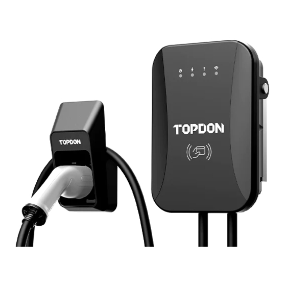
Page 9: Section 3- Product Overview & Info
Section 3— PRODUCT OVERVIEW & INFO 3.1 Shape & Dimensions The shape & dimensions of PulseQ AC Home charger are shown as Fig. 3.1.1 220mm 95mm 310mm Fig. 3.1.1 The shape & Dimensions of PulseQ AC Home 3.2 Block diagram The block diagram of PulseQ AC Home charger is shown as Fig. -
Page 10: Electrical Specifications
It is widely used in various household electric vehicle charging in Europe, as well as various chargers, parking lots, community garages and public electric vehicle charging places. 3.3 Specifications 3.3.1 Electrical Specifications Model Number PULSEQ AC HOME Rated Voltage 230V/400V, 50/60Hz Rated Current 32A 1-Phase/16A 3-Phase/32A 3-Phase... -
Page 11: Mechanical Parameters
3.3.3 Mechanical Parameters Mounting Wall-mounted Net Weight ≤ 7KG(5m cable)、≤ 9KG(7.5m cable) H×W×D = 310mm × 220mm × 95mm Dimension Front cover: Gray, PC; Back cover: Black, PC Color & Material IP Code IP65 IK Code IK10 3.3.4 Ambient Conditions Altitude ≤... - Page 12 3.3.5 Nameplate This equipment should be reliably grounded before use. Installation, wiring and maintenance should be done by personnel with professional qualification. Do not expose to flammable gas. Failure to read user manual carefully before use may lead to improper operation. Model No.: PulseQ AC Home_7K_EU PulseQ AC Home_11K_EU...
-
Page 13: Section 4-What's In The Box
Section 4—What's in the Box? AC EV Charger (5m charging cable) Charging Dock Wall-mounting Accessories User Manual Quick User Guide Quality Certificate Wall Installation Template M6×63mm Expansion Bolt M5×40mm Expansion Bolt Charging Dock Installation Template IC card User Manual... -
Page 14: Section 5-Installation
Section 5—Installation 5.1 Pre-Installation Inspection When unpacking, please carefully confirm the following points: ● Whether the accessories are missing according to the packing list. ● Whether there is any damage during transportation. ● Whether the model and specification of the machine's nameplate are consistent with the order requirements. If any damage or missing parts are found, please do not start the installation, and contact us as soon as possible. -
Page 15: Tools For Installation
5.3 Tools for Installation Please prepare the following tools before installation Tools’ Name Schematic Picture Main Uses Check the electrical connection and Multimeter measure the voltage Electric Impact Drill fixing holes in the wall drill Wrench Fastening bolt Diagonal plier Cut the cable Wire stripper Peeling cables... -
Page 16: Wall Bracket Installation
5.4 Wall Bracket Installation Ensure the homeowner has chosen an installation location that allows the charging cable to reach the car's charging port while still providing slack. Ensure there is a stud available at the desired location for mounting he charging station. - Page 17 Mark the mounting hole on the wall with the installation template. (See Fig. 5.4.3) Fig. 5.4.3 Drill the mounting holes on the wall with a depth of at least 1.97". (See Fig. 5.4.4) Fig. 5.4.4 Hammer the expansion sleeve into the corresponding hole (See Fig. 5.4.5) 1.97"...
- Page 18 Fix the bracket to the wall with the expansion screws (See Fig. 5.4.6) included in the package. Fig. 5.4.6 Attach the charger to the bracket.(See Fig. 5.4.7) Fig. 5.4.7...
-
Page 19: Hardwire Installation
5.5 Hardwire Installation The hardwire installation needs to be done by electricians, and please strictly follow the safety precautions. Unscrew the six screws on the back cover with a Phillips screwdriver, and remove the front cover. (See Fig. 5.5.1) Fig. 5.5.1 Unscrew the gland at the bottom of the charging station. - Page 20 Use a wire stripper to remove 10~12 mm of insulation from the wire conductor. (See Fig.5.5.3) 10-12mm Fig. 5.5.3 Turn over the wirebox. Loosen the five screws with a flat-blade screwdriver and fully insert the wire conductors into the connectors on the terminal block. Tighten the screws and make sure each wire conductor is securely connected.
- Page 21 Reinstall the front cover and tighten the gland.
- Page 22 5.6 Charging Dock Installation Please make sure the space on the wall is at least 2.12" × 2.12" (54mm × 54mm). 54mm 54mm Place the installation template on the wall and mark the mounting hole. (See Fig. 5.6.1) Fig. 5.6.1 Drill the mounting holes on the wall with a depth of at least 1.97".
- Page 23 Fit the charging plug socket into the charing dock (See Fig. 5.6.3) Fig. 5.6.3 Fix the charging dock on the wall with the expansion screw in the package. (See Fig. 5.6.4) Fig. 5.6.4 Please put the charging plug back to the Charging Dock after each charge.
-
Page 24: Section 6-Network Configuration
Section 6—Network Configuration 6.1 Wi-Fi Configuration To configure the Wi-Fi, please download the PulseQ application from the APP Store and Google Play and install the app to your phone. (See Figure 6.1.1) Fig.6.1.1 Register an account with your email address and login. (See Figure 6.1.2) Open the app and tap the User Center, select the charging station management. - Page 25 Tap the cross at the bottom right to add your charging station. (See Figure 6.1.4) Select the Wi-Fi network. (See Figure 6.1.5) Fig.6.1.4 Fig.6.1.5...
- Page 26 Tap the TOPDON- AC Home to connect the hotspot. (See Figure 6.1.6) Tap the Wi-Fi Setting, enter the Wi-Fi name and password to set up the connection. (See Figure 6.1.7) Fig.6.1.6 Fig.6.1.7...
- Page 27 Once the above steps have been done, tap the Confirm to complete the procedure. (See Figure 6.1.8) Fig.6.1.8...
-
Page 28: Section 7-Led Indicators
Section 7—LED Indicators The LED indicators on the panel are used to indicate the status of the charger and the various combinations of indicators are described as below. Icon Indicator Color Indicator Status Connotation Standby status Green Twinkle Ground fault status Connected to an EV Green BLN control... -
Page 29: Section 8-Fault Handling
Section 8—Fault Handling If All LED are not on, please check: ▷ Whether the power supply and distribution are normal; ▷ Whether the branch breaker is tripped, and close the breaker after troubleshooting; ▷ Whether the connection is correct, if the cable comes off, should be properly connected to tighten the cable. -
Page 30: Section 9-Warranty
Notice: All information in this manual is based on the latest information available at the time of publication and no warranty can be made for its accuracy or completeness. TOPDON reserves the right to make changes at any time without notice.
Need help?
Do you have a question about the PulseQ AC Home and is the answer not in the manual?
Questions and answers