Table of Contents
Advertisement
Quick Links
Advertisement
Table of Contents

Related Manuals for Eicom ENO-30

Summary of Contents for Eicom ENO-30
- Page 2 NOx Analyzer (ENO-30) User’s Guide Distributed by Eicom USA: 7098 Miratech Dr, Ste 100, San Diego, CA 92121, USA Phone: (888) 680-7775 FAX: (858) 560-8040 Email: info@eicom-usa.com Distributed by Eicom Europe: Hilton House Ardee Rd, Ground Floor, Rathimines Dublin 6, Ireland...
-
Page 3: Table Of Contents
Contents 1. INTRODUCTION --------------------------------------------------------------------------------------------------------------------------- 1 1-1. About this user’s guide ----------------------------------------------------------------- 1 1-2. Important Safety Information --------------------------------------------------------- 2 2. OVERVIEW ---------------------------------------------------------------------------------------------------------------------------------- 3 2-1. Principle of Measurement ------------------------------------------------------------- 3 2-2. Schematic of Parts and Functions -------------------------------------------------- 4 2-3. Tubing Flow Diagram ------------------------------------------------------------------- 6 2-4. - Page 4 6-8. Start up ----------------------------------------------------------------------------------- 28 7. SAMPLE INJECTION ------------------------------------------------------------------------------------------------------------------- 29 7-1. Manual Injector Operation ----------------------------------------------------------- 29 7-2. Sample Amount ------------------------------------------------------------------------ 30 7-3. Autosampler Operation (optional) ------------------------------------------------- 30 8. SHUTDOWN AFTER ANALYSIS ----------------------------------------------------------------------------------------------------- 31 8-1. Short Shutdown, less than 2 weeks ---------------------------------------------- 31 8-2.
-
Page 6: Introduction
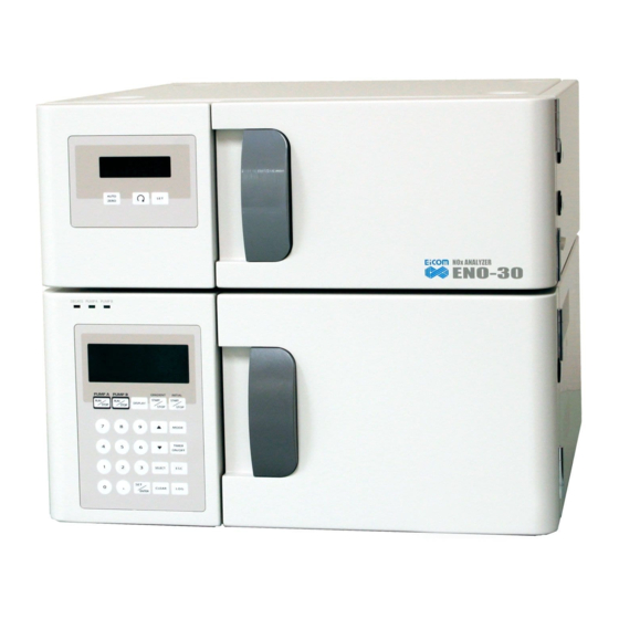
1. Introduction Thank you for purchasing the Eicom NOx Analyzer (ENO-30). Please read this user’s guide before use. The ENO-30 is an HPLC-based system designed to perform high sensitivity analysis of Nitrite and Nitrate in biological samples. The lower half of the system is the pump unit. It has two independent pumps and a two channel online degasser. -
Page 7: Important Safety Information
1-2. Important Safety Information We insist that users observe the following procedures in order to prevent accidents: 1) Be sure to read and understand this manual completely prior to operating the ENO-30. 2) Follow all warnings listed herein very closely. -
Page 8: Overview
2. Overview 2-1. Principle of Measurement The ENO-30 is a high sensitivity instrument for measuring nitrite and nitrate ion level in biological fluids. This is achieved by combining a colorimetric diazo coupling method (Griess) with the advantages of HPLC. After the sample is injected it is filtered by the guard column. Then the separation column interacts with the ions in such a way that they flow though the column at different rates. -
Page 9: Schematic Of Parts And Functions
2-2. Schematic of Parts and Functions 1. Pump control panel Set the flow rate of each pump and the upper pressure limit. Then start and stop the pump. 2. Degasser This degasser removes dissolved air from the Carrier and Reactor solutions before they enter the pumps. - Page 10 It supplies the reactor solution to the reaction coil. 5. Reactor Backpressure Coil It maintains high enough pressure that the reactor pump can work efficiently. 6. Manual Injector (and/or Autosampler) Manual injection of up to 50 µL of sample using a blunt ended Hamilton syringe can be made here.
-
Page 11: Tubing Flow Diagram
2-3. Tubing Flow Diagram Please use this diagram as a guide in make all the proper tubing connections. Important points: The column effluent (Carrier) and the Reactor solution should enter the 3-way joint on opposite sides of the straight part of the joint to improve mixing. ... -
Page 12: Pump Seal Wash
Valve S top The ENO-30 has a pump seal wash function, which greatly expands the pump seal lifetime, and prevents damage to the inside of the pump. Small amount of salt containing liquid can leak passed the seal. If it is allowed to crystallize, the salt crystals will scratch the piston and seal, causing premature wear and eventually leakage. -
Page 13: Fittings And Tubing
2-5. Fittings and Tubing There are two main types of fittings used to connect tubing on the ENO-30. Easy Fit The Easy Fit connector is for column joints and other high pressure locations. Before tightening the nut, push the tubing end all the way through the Easy Fit connector until it stops inside the connection, and hold it in place while you screw down the nut. - Page 14 45˚ with a wrench. Tubing (installation) Generally, Eicom or its distributor will install the ENO-30 and connect all tubes. In the event that you have to reconnect the tubing yourself, please refer to the following points.
-
Page 15: Installation
Maintain sufficient space around the ENO-30 to ensure adequate ventilation. 3-2. Power Plug Power supply conditions of ENO-30 are as follow. Please make sure to use the included triple core cable with grounding wire as power supply. Power supply Voltage: AC 100V~240V Single Phase (±10V) -
Page 16: Electrical Connections (Detector Unit Side Panel)
3-3. Electrical connections (Detector Unit side panel) The ENO-30 is set up when delivered by Eicom or its distributor. If for some reason, you set up the electrical connectors of the ENO-30 by yourself, please use the diagram below as a guide. -
Page 17: Electrical Connections (Pump Unit Signal Terminal)
3-4 Electrical Connections (Pump Unit Signal Terminal) If you have an autosampler installed this communication signal terminal may be of use to you. Otherwise, you don’t need to connect anything here. See below on how the <ERROR OUT> signal can be used. -
Page 18: Manual Injector Tubing Connections
3-5. Manual injector Tubing Connections At the back of the manual injector: Port #1 and #4 has the sample loop Port #2 receives the tubing from the Carrier pump Port #3 goes to the precolumn/separation column, or if installed, to an autosampler. -
Page 19: Pump Unit Operation
4. Pump Unit Operation 4-1. Pump overview The ENO-20 has the very precise liquid delivery pump with double pistons. The reciprocal action of the 2 pistons provides for continuous pulseless flow of the mobile phase. Check Valve (Outlet) Back up Ring Piston Washing Seal Front... -
Page 20: Power On
PUMP B PUMP B Pump Off timer is in Green Blinks operation *DEGASS When the indicator blinks red, there is a problem inside the degasser. Please contact Eicom or one of its distributors immediately. 15 | P a g e... -
Page 21: Key Pad
4-3. Key Pad Display Keypad 16 | P a g e... - Page 22 Name Function PUMP A In Isocratic Mode, controls the start or stop of pump A RUN/STOP PUMP B In Isocratic Mode, controls the start or stop of pump A RUN/STOP DISPLAY Cycles the display between various menus GRADIENT In Gradient Mode, controls the start or stop programmed START/STOP gradient method INITIAL...
-
Page 23: Display Screen
4-4. Display Screen There are 2 screens that can be displayed. 1) “FLOW RATE/ PRESS” 2) “P.LIM/P.FREE/TIMER (Pressure Limit/Pulse Free mode/Timer)”. PUMP A FLOW RATE/PRESS. PUMP B FLOW RATE/PRESS <FLOW RATE/ PRESS> Displays the set flow rate and current pressure. Switch display key PUMP A PUMP B... -
Page 24: Adjusting The Settings
4-6. Adjusting the Settings Standard pump settings are: Carrier Pump: 0.33 mL/min Reactor Pump : 0.10 mL/min Pressure Limit: 10 MPa Pressure Limit: 10 MPa Set the Flow Rate Set the Carrier (PUMP A) flow rate to 0.33 mL/min and Reactor (PUMP B) to 0.10 mL/min. Press SET/ENTER key once Cursor (>) appears next to PUMP A Set flow rate with keys... - Page 25 Set the Pressure Limit and Pulse-free Mode Now set the Pressure Limit for both pumps to 10MPA Switch screen by pressing DISPLAY Press SET/ENTER once. Cursor (>) appears in PUMP A Enter pressure limit with keys 1 Press SET/ENTER once. Cursor (>) moves to Pulse Free Mode.
- Page 26 Indicator in main body turns green to show that PUMP A is running. Use Isocratic mode only This pump unit also has a gradient function that is not used on the ENO-30. If you accidentally get in to the Gradient Mode <GRA>, you need to switch back to the Isocratic Mode (<ISO>).
-
Page 27: Priming The Pump/ Purge Valve Operation
4-7. Priming the Pump/ Purge Valve Operation The purge valve is used to prime the pump. Air is removed and mobile phase in the degasser and pump is exchanged for new fluid. When the purge valve is open, the pump pushes solution out of the valve, instead of to the column and rest of the system. -
Page 28: Pump Error Messages
*Error 3 and Error 4 occur only in Pulse Free Mode ON. Error message via status indicator light Indication Cause Handling Vacuum pressure in It may require maintenance procedure. degasser is not reaching Please contact Eicom or its distributors DEGASS correct value. immediately. Blinks Red 23 | P a g e... -
Page 29: Detector/Oven Operation
5. Detector/Oven Operation 5-1. Power Switch The power switch is on the left side, not too far back and toward the bottom edge. As soon as the Detector Unit is turned on, the oven will begin to heat. You should feel air blowing inside the chamber. -
Page 30: Analysis
6-2. Water Quality All water used for ENO-30 maintenance and sample preparation must be super pure water (18.2 Mega-Ohm x cm). Distilled or deionized water may be used, although this is not ideal for ENO-30 and accurate analysis. -
Page 31: Carrier And Reactor Solutions Preparation
For analysis of NO and NO , the Carrier and Reactor should be prepared using Eicom Carrier Powder (NO-CAP3) and Reactor A and B powders (NO-RAP3 and NO-RBP3). Reactor A and B solution are made separately and just enough for one day’s analysis is prepare by mixing 1:1. -
Page 32: Standard Solution
6-5. Standard Solution Dissolve the necessary amount of NaNO and NaNO in water taken directly from the purified water tap. Then prepare a standard curve by diluting into water, Carrier solution, or the same solution as the sample is in. 6-6. -
Page 33: Start Up
(30-60 mins) 10. Inject 10 µL of 10 µM standard solution a calibration chromatogram. The sensitivity of ENO-30 must be check by a standard solution before each analysis. The peak height of should be over 16 mV (10 µL 10 µM= 100 pmol). -
Page 34: Sample Injection
7. Sample Injection Always use correct blunt ended needle to make injections or risk damaging the valve! The standard syringe is a 25 µL Hamilton syringe (702SNR). However, a 50 µL syringe may also be used (705SNR). When the injector knob is moved between LOAD and INJECT, the flow pattern is switched. In the INJECT position the flow from the pump passes through the sample loop and on to the column. -
Page 35: Sample Amount
7-2. Sample Amount The ENO-30 accepts 1-50 µL of sample or standard. For accurate analysis, the same quantity of sample or standard should be used. It’s best if the samples and standard are in the same solutions. Use Carrier solution to dilute samples that are too high. -
Page 36: Shutdown After Analysis
8. Shutdown after Analysis Extended storage period procedures are very important for the ENO-30. If the next analysis will be in less than two weeks, then you can follow the procedure in section 13-1. If it will be more than two weeks, follow the procedure in section 13-2. -
Page 37: Restart
9-2. After short shutdown procedure In case the ENO-30 was left containing Carrier and Reactor for more than just a couple of days or up to two weeks, it may be necessary to clean the system, but first you can check the system condition. - Page 38 6. Stop the pumps and set to standard flow rates. 7. Install the columns and start the pumps, Carrier first. 8. Let the ENO-30 stabilize for 30 mins and inject standard solution to check sensitivity. 33 | P a g e...
-
Page 39: Precolumn
200 injections for lower protein samples. These numbers are strongly influenced by sample preparation methods, precolumn packing and so forth. Please refer to unit 15-1. (About sample preparation, please refer to Eicom technical publication entitled “Nitrite and Nitrate Analysis” ) 10-1. -
Page 40: How To Repack The Precolumn
10-2. How to Repack the Precolumn 1) Turn off the reactor pumps and then turn off the carrier pumps. 2) Remove the guard column and replace with a two way joint. 3) Open the precolumn using two wrenches. Then remove the old packing material and wash out the inside of the empty column. - Page 41 with the end cut off) to transfer the slurry to the pre-column. Set the pipette volume to 20 µL. Apply the slurry to the pre-column as you slowly aspirate with the syringe. The idea is to pull excess methanol through the column to make room for more slurry, but without letting the material go dry.
-
Page 42: Filter Exchange
the outlet side of the precolumn. Failure to pack correctly will cause the peaks shapes to appear strange, except when the pre-column has been place ahead of the injector. 10) If the peak shape of the standard sample doesn’t improve with the newly re-packed column, but is still good when only the separation column is in place, the pre-column needs to be repacked again. -
Page 43: Separation Column (No-Pak)
11. Separation Column (NO-PAK) 11-1. NO-PAK The size of the separation column (NO-PAK) is ø4.6 mm and 50 mm in length, and it is packed with a styrene polymer gel. The separation quality of column is verified before shipping. ... -
Page 44: Reduction Column (No-Red)
12. Reduction Column (NO-RED) 12-1. Structure and Maintenance is reduced to NO by the reduction column, but NO is not reactive with cadmium. The reduction column contains cadmium and reduced copper which are consumed by the delivery of solvent. To fill the space made by consuming of cadmium/copper, tighten the screw to clockwise (arrow in figure) before analysis once a day. -
Page 45: Troubleshooting
13. Troubleshooting In the case that your analysis can not be performed by the ENO-30, and that troubles persist after reading this document, please refer to this chapter. Please inject a standard sample to find the cause of trouble. If this chapter is not helpful, please contact Eicom. -
Page 46: High Carrier Pump Pressure
4) The next method is to force liquid through the pump head by connecting a syringe to the three way joint at the bottom of the pump head. There are details in video available on the Eicom users’ site or directly from your Eicom representative. 13-4. High Carrier Pump pressure Check the guard column. -
Page 47: Maintenance
14. Maintenance 14-1. Pump Head Parts A parts breakdown of a pump head is as follows. Part Number Part Name 1Pump Head Fix Nut 2Pump Head Washer 3Check Valve (Inlet) 4Check Valve (Outlet) 5Pump Head 6Piston Seal 7Backup Ring 8O-Ring 9Pump Head Guide Nut 10Pump Head Guide Nut Washer 11Washing Port... -
Page 48: Changing The Piston Seal And Piston
14-2. Changing the Piston Seal and Piston 1. Remove tube connectors from the inlet and outlet check valves. Take off pump head by loosening the nuts (2) washer. s you loosen them, alternate between asher them. Pump Head Fix Nut 2. - Page 49 Short Rod 7. Remove now free old piston seal from the replacement tool. Piston seal Remove Long Rod 8. To install the new piston seal place it on the short rod of the replacement tool as shown in the figure to the left and wet with water.
- Page 50 4. Put small rod of the piston replacement tool into hole in metallic part at the base of the piston shaft, and use a counterclockwise motion to loosen it. 5. After loosen piton, remove it by hand. Then, remove the wash seal as well. 6.
- Page 51 12. Tightens up pump head guide nuts by alternative between the two screws until they are completely seated 13. Reconnect the tubing to the check valves, and the process is completed. 46 | P a g e...
-
Page 52: Appendices
2. Connect the AS-700 output (black and red wires from the 3-wire portion of the signal cable) to the AUTOZERO/SIG. IN of ENO-30. 3. Connect the CPU of the ENO-30 to the Detector 1 of the EPC-700 data processor. 4. Connect the SIG.OUT of the ENO-30 to the INPUT 1 of the EPC-700 data processor. -
Page 53: Specifications
15-2. Specifications Detector/ Oven Unit Detection Principle Light absorption at 540 nm (diazo compound) Detection limit 10 nM × 10 µL (0.1 pmol) 15 °C – 45 °C at room temp of 25 °C Temperature Control Temperature accuracy ± 0.1 °C Weight ~ 11 kg Power... -
Page 54: Sample Preparation
15-3. Sample Preparation 1. Tissue Homogenate Add methanol at a concentration of 2 mL/g tissue. Homogenize (in an ice bath, preferentially). Centrifuge at 10,000 G for 10 min (at 4ºC, preferentially). Inject the collected supernatant. Note: If the concentration is too high, add the same volume of carrier solution to the supernatant. - Page 55 All rights reserved by Eicom. Use of images and /or wording of this manual without express permission are completely prohibited. Specifications and descriptions in this user guide are subject to change without prior notice. If you have any further questions, please feel free to contact to Eicom or its distributors...
Need help?
Do you have a question about the ENO-30 and is the answer not in the manual?
Questions and answers