
Related Manuals for ZF-DUOPLAN 2K800


Summary of Contents for ZF-DUOPLAN 2K800
- Page 1 OPERATING INSTRUCTIONS Two-speed Gearbox 2K800 / 2K801 / 2K802 10.2006 Edition 4161 758 103g...
- Page 2 2K800/2K801/2K802 NOTE These operating instructions also apply to the predecessor model 2K50. Subject to alterations in design Copyright by ZF Reproduction, in whole or in part, is only allowed with our written approval and authorization. Printed in Germany Edition 10.2006...
-
Page 3: Table Of Contents
3.2.2 Full-key balancing ........................12 Adaptation, motor/gearbox ......................13 3.3.1 Open design ..........................13 3.3.2 Close design (with shaft sealing ring)..................14 3.3.3 Open design with adapter ring for 2K800 and 2K801 ..............15 3.3.4 Open design with adapter ring for 2K802..................15 Gearbox - fit..........................16 Output ............................17 3.5.1 Version with belt output ......................17... - Page 4 Operating Instructions Contents 2K800/2K801/2K802 Maintenance............................32 Oil change ............................32 Repair ..............................33 Gearbox fault checklist ........................33 Gearbox - disassemble .........................34 Hub...............................34 Frequently Asked Questions (FAQ) ....................35...
-
Page 5: Preface
Operating Instructions 2K800/2K801/2K802 Preface Preface Safety instructions This documentation is intended for specialists who • All persons repairing ZF units are responsible have experience to carry out maintenance and re- for their own work safety. pair work. • Every applicable safety regulation and legal... -
Page 6: Service Products
Operating Instructions Preface 2K800/2K801/2K802 Service products Product Name/specification Quantity Remarks (approx.) Grease Shell Avania WR2 General-purpose Fuchs Renolit CXEP2 Esso Beacon EP2 Gearbox oil Gearbox oil for Can also be used for HLP 46 to ISO VG 46 recirculating recirculating lubrication... -
Page 7: Application And Design
2K800/2K801/2K802 Application and Design Application and Design Application The ZF-DUOPLAN two-speed gearbox is mainly used in machine tool drives. By way of example, the gearbox can be used in turning machines (horizontal B5) or machining centers (vertical V1) thanks to its variable installa- tion position. -
Page 8: Design
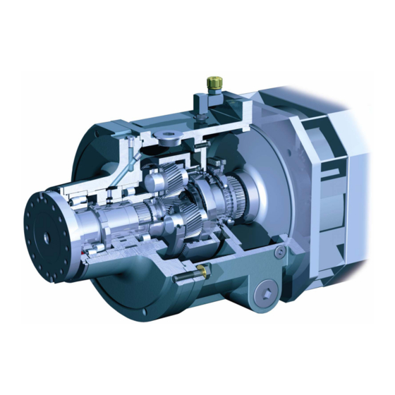
Operating Instructions Application and Design 2K800/2K801/2K802 Design Output The gearbox primarily comprises the following • Bearing housing (9) assemblies: • Output bearings (10, 11) Connecting parts • Output shaft (12) • Drive hub (1) • Radial shaft seal (13) • Adapter plate (2) with radial shaft seal (3) and •... -
Page 9: Technical Data
Operating Instructions 2K800/2K801/2K802 Application and Design Technical data Type 2K800 2K800 2K800 2K800 2K801/802 2K801/802 2K801/802 2K801/802 Standard with STW Standard with STW version (i=1.236) version (i=1.236) Nominal input max. 800 Nm max. 800 Nm Nominal power max. 84 kW max. 84 kW... -
Page 10: Installation Positions
Operating Instructions Application and Design 2K800/2K801/2K802 Installation positions Horizontal B5 Horizontal B5 (shift unit rotated) Vertical V1 Vertical V3 027929 CAUTION The breather outlet must always be at the top, regardless of the installation position. -
Page 11: Initial Installation
In order to guarantee fault-free operation, the mo- tor must not exceed the specified tolerances. 001064 Axial runout, radial runout and length tolerances – electric motor mounting flange: Gearbox Tolerance type L=140 2K800 / 0.030 0.063 0.063 ± 0.200 2K801 L=140 2K802 0.030 0.063... -
Page 12: Balancing
Operating Instructions Initial Installation 2K800/2K801/2K802 Balancing The hubs (2) come with a keyway (1) for trans- mitting power from the motor shaft (3) as stan- dard. There are two balancing types for the motor and gearbox: Semi-key and full-key, which are de- scribed in more detail in DIN ISO 8821. -
Page 13: Adaptation, Motor/Gearbox
Operating Instructions 2K800/2K801/2K802 Initial Installation Adaptation, motor/gearbox CAUTION Risk of motor shaft damage if the hub is not The motors must have a flange-mounting option sufficiently heated. for mounting the gearboxes. Tighten the threaded pin (9) and secure it to pre- The gearbox housing is fitted to the motor by vent it from turning, see section 3.4. -
Page 14: Close Design (With Shaft Sealing Ring)
Operating Instructions Initial Installation 2K800/2K801/2K802 3.3.2 Close design (with shaft sealing ring) This variant incorporates an adapter plate (5) with shaft seal (7), which means that the gearbox forms a compact, closed unit. The adapter plate (5) and drive hub (1) are sepa- rately delivered loose. -
Page 15: Open Design With Adapter Ring For 2K800 And 2K801
2K800/2K801/2K802 Initial Installation 3.3.3 Open design with adapter ring for 2K800 and 2K801 The adapter ring allows adaptation to different connection dimensions. A seal is required on the motor output shaft. The adapter ring (5) and drive hub (1) are deliv- ered loose. -
Page 16: Gearbox - Fit
Operating Instructions Initial Installation 2K800/2K801/2K802 CAUTION Risk of motor shaft damage if the hub is not sufficiently heated. Tighten the threaded pin (9) and secure it to pre- vent it from turning, see section 3.4. Gearbox - fit NOTE When fitting the drive hub (1), screw in and tighten the threaded pin (9) onto the fitted key. -
Page 17: Output
Operating Instructions 2K800/2K801/2K802 Initial Installation Output Electrical connection, gearchange The gearbox is electrically connected using the supplied 8-pole Harting connector (HAN 8 U). 3.5.1 Version with belt output The plug-in connection is located on the shift unit. The belt pulley must be centered on the outer diameter of the output flange (tolerance K6), fas- 3.6.1... - Page 18 Operating Instructions Initial Installation 2K800/2K801/2K802 During the gearchange, the main spindle motor Circuit diagram for switchgear unit with sole- should make the shaft oscillate +5° at a rate of noid unit and two switch positions (standard) 1 to 5 rotation direction changes per second. The...
-
Page 19: Switching Unit With Servo-Motor
Operating Instructions 2K800/2K801/2K802 Initial Installation 3.6.2 Switching unit with servo-motor The switching positions are monitored by stop switches inside the switching unit. A time relay Specifications: has been provided for monitoring the time lapse Power rating that, if necessary, will reset the process if the... - Page 20 Operating Instructions Initial Installation 2K800/2K801/2K802 Circuit diagram for a switching unit with three switch positions (with neutral position): Gear ==> e.g. 4:1 Gear ==> Gear ==> neutral switch position, idle running (option) The gearing is connected up electrically using the 8-pin Harting plug (HAN 8 U) supplied by us.
-
Page 21: Switching Logic For Switching Unit With Solenoid Unit
Operating Instructions 2K800/2K801/2K802 Initial Installation 3.6.3 Switching logic for switching unit with solenoid unit Reduce main spindle motor speed from operating speed to zero. Leave controller enable on converter. Apply desired oscillating speed to converter and speed controller without delay. -
Page 22: Switching Logic For Switching Unit With Solenoid Unit And Centre Position
Operating Instructions Initial Installation 2K800/2K801/2K802 3.6.4 Switching logic for switching unit with solenoid unit and centre position Reduce main spindle motor speed from operating speed to zero. Leave controller enable on converter. Apply desired oscillating speed to converter and speed controller without delay. -
Page 23: Switching Logic For Switching Unit With Servo-Motor
Operating Instructions 2K800/2K801/2K802 Initial Installation 3.6.5 Switching logic for switching unit with servo-motor Reduce main spindle motor speed from operating speed to zero. Leave controller enable on converter. Apply desired oscillating speed to converter and speed controller without delay. Servomotor for gear ratio... -
Page 24: Switching Logic For Switching Unit With Servo-Motor And Centre Position
Operating Instructions Initial Installation 2K800/2K801/2K802 3.6.6 Switching logic for switching unit with servo-motor and centre position Reduce main spindle motor speed from operating speed to zero. Leave controller enable on converter. Apply desired oscillating speed to converter and speed controller without delay. -
Page 25: Lubrication
• An oil-air emulsion is formed in the oil return NOTE and in the tank. The 2K800, 2K801 and 2K802 gearboxes must always be operated with recirculating lubrication. 3.7.1.1 Recirculating lubrication for V1/B5 In this case, the oil level is not visible in the oil operation sight glass. - Page 26 Operating Instructions Initial Installation 2K800/2K801/2K802 3.7.1.3 Recirculating lubrication with Installation example B5 intermediate tank The tank volume should be at least ten times the recirculating oil quantity in order to ensure effec- tive oil cooling. NOTE To prevent gearbox damage due to lack of oil, ZF recommends you install an oil level sensor at the intermediate tank.
-
Page 27: Ports And Connections For Recirculating Lubrication
Operating Instructions 2K800/2K801/2K802 Initial Installation 3.7.2 Ports and connections for recirculating lubrication 028049 Installation position Oil inlet port Max. pressure Oil return port G and F 0.5 l/min 3 bar 2.5 l/min 5 bar D and E 0.5 l/min 3 bar L (with suction) 2.5 l/min... -
Page 28: Gearbox Oil Pump (Option)
Operating Instructions Initial Installation 2K800/2K801/2K802 3.7.3 Gearbox oil pump (option) 3.7.3.1 Specifications Supply volume 3.4 dm / min. Electrics: Nominal voltage: 400V 50 Hz Nominal rating: 100W Operating mode: S1 = 100% ED Protection category: IP 44 Nominal speed: 2 850 revs/min... - Page 29 Operating Instructions 2K800/2K801/2K802 Initial Installation 3.7.3.2 Connection for nominal voltage 100-120 V AC Terminal diagram 100 – 120 V AC: Circuit diagram for 100 – 120 V AC: Termi- Jumpers Capacitor C • voltage • • • Temperature monitoring •...
-
Page 30: Heat Exchanger (Option)
Operating Instructions Initial Installation 2K800/2K801/2K802 3.7.4 Heat exchanger (option) Type TL 1 The heat exchanger cooler fan is driven by a 24 V D.C. motor. The rotation direction of the cooler fan must match the Rotation direction marking on the housing (note suction direction). - Page 31 Operating Instructions 2K800/2K801/2K802 Initial Installation Type TL 4 Rotation direction Circuit diagram: Customer side Blower-side interface...
-
Page 32: Taking Into Operation
Operating Instructions Taking into Operation 2K800/2K801/2K802 Taking into Operation Maintenance Initial inspection Oil change Check that the gearbox is correctly installed Oil change interval: Every 5000 operating before taking it into operation. hours • Mechanical fastening ENVIRONMENTAL HAZARD! • Motor flange-mounting... -
Page 33: Repair
Operating Instructions 2K800/2K801/2K802 Repair/Maintenance Repair Questions for fault diagnosis: Is gearbox oil sight glass dark/discolored • In the event of gearbox malfunctions, first check black? the connected components and their ports and connections. Smell of burning oil at oil breather? •... -
Page 34: Gearbox - Disassemble
Frequently Operating Instructions Asked Questions (FAQ) 2K800/2K801/2K802 Gearbox - disassemble (e.g. version with adapter plate and shaft seal) Proceed accordingly in the case of other versions. • Switch off the machine • Switch off the power supply • Disconnect the electrical connections •... -
Page 35: Frequently Asked Questions (Faq)
Operating Instructions Frequently 2K800/2K801/2K802 Asked Questions (FAQ) Frequently Asked Questions (FAQ) Error Cause of error Remedy Gearbox is loud, knocking • Loose contact on motor speed Check speed sensor and electrical noises sensor, which causes permanent lines to motor, clean speed sensor if motor governing. - Page 36 Frequently Operating Instructions Asked Questions (FAQ) 2K800/2K801/2K802...
- Page 37 ZF Friedrichshafen AG Sonder-Antriebstechnik Ehlersstraße 50 • D-88046 Friedrichshafen Phone: ++49 (75 41) 77-0 • Fax: ++49 (75 41) 77-34 70 E-mail: ZFM.Sales@zf.com • Internet: www.zf.com...
Need help?
Do you have a question about the 2K800 and is the answer not in the manual?
Questions and answers