
Related Manuals for ZF-DUOPLAN 2K120


Summary of Contents for ZF-DUOPLAN 2K120
- Page 1 Operating Instructions Two-speed Gearbox 2K120 / 2K121 08.2013 Edition 4161 758 101j_en...
- Page 2 2K120/2K121 Subject to alterations in design Copyright by ZF Reproduction, in whole or in part, is only allowed with our written approval and authorization. Printed in Germany Edition: 2013-08 4161 758 101j...
-
Page 3: Table Of Contents
Operating Instructions 2K120/2K121 Contents 1 Preface ........................... 5 Safety instructions ........................5 ZF instructions ...........................5 Service products ........................6 2 Application and Design ......................7 Application ..........................7 Features ............................7 Design ............................8 ... - Page 4 Operating Instructions Contents 2K120/2K121 4 Taking into Operation ......................27 Initial inspection ........................27 5 Maintenance ......................... 27 Oil change ..........................27 6 Repair ........................... 28 Gearbox fault checklist ......................28 Gearbox – disassemble ......................29 ...
-
Page 5: Preface
Operating Instructions 2K120/2K121 Preface Preface Safety instructions • This documentation is intended for specialists who All persons repairing ZF units are responsible for have experience to carry out maintenance and their own work safety. repair work. • Every applicable safety regulation and legal... -
Page 6: Service Products
Esso Beacon EP2 Gearbox oil Gearbox oil for Can also be used for HLP 68 to ISO VG 68 splash lubrication recirculating lubrication 2K120 – and recirculating Installation pos. B5 lubrication with heat 2K121 – exchanger Installation pos. B5 Gearbox oil... -
Page 7: Application And Design
2K120/2K121 Application and Design Application and Design Application The ZF-DUOPLAN two-speed gearbox is mainly used in machine tool drives. By way of example, the gearbox can be used in turning machines (horizontal B5) or machining centers (vertical V1) thanks to its variable installation position. -
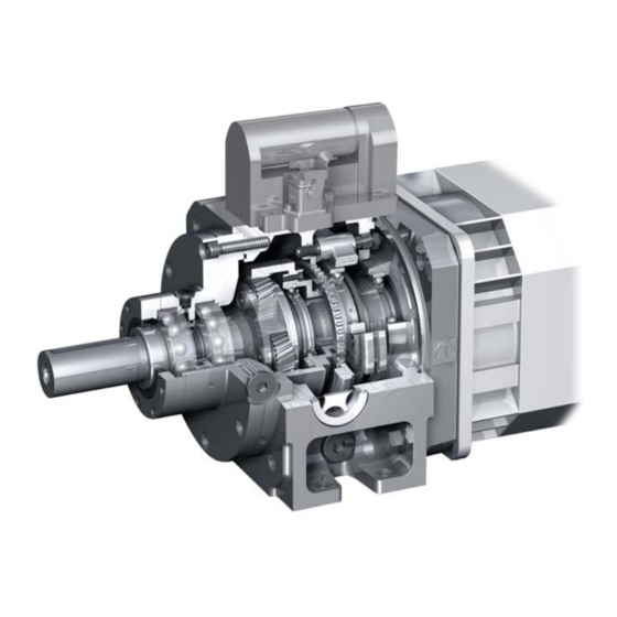
Page 8: Design
Operating Instructions Application and Design 2K120/2K121 Design The gearbox primarily comprises the following Output: assemblies: • Bearing housing (9) • Output bearings (10, 11) Connecting parts: • Output shaft (12) • Drive hub (1) • Radial shaft seal (13) • Adapter plate (2) with radial shaft seal (3) and •... -
Page 9: Technical Data
= 4.00 480 Nm (continuous operation): max. 120 Nm i = 4.91 589 Nm Max. speed Weight approx. 42 kg (2K120) in ratio i≠1 8000 rpm approx. 52 kg (2K121) in direct drive i=1 (with gearbox oil cooling) 12000 rpm See chap. -
Page 10: Installation Positions
Operating Instructions Application and Design 2K120/2K121 Installation positions Horizontal B5 Horizontal B5 Shift unit on right side, gearbox turned around longitudinal axis (view to output end) Vertical V1 Vertical V3 CAUTION The breather outlet must always be at the top,... -
Page 11: Initial Installation
Undersize shafts must be compensated for by using shims when mounting to the motor. Oversize shafts must be machined to the correct length. Take into account the permitted axial forces on the motor shaft. Also see ZF-DUOPLAN catalogue (4161 750 102), “Performance data” chapter. -
Page 12: Balancing
Operating Instructions Initial Installation 2K120/2K121 Balancing The hubs (2) come with a keyway (1) for trans- mitting power from the motor shaft (3) as standard. There are two balancing types for the motor and gearbox: Semi-key and full-key, which are described in more detail in DIN ISO 8821. -
Page 13: Adaptation, Motor/Gearbox
2K120 33.3-0.2 2K121 53.3-0.2 CAUTION Dimension C 32.8-0.2 (2K120) or 52.8-0.2 (2K121) in the case of motors with fixed bearing on the B-side. 3.3.1 Open design The open version is the gearbox without adapter plate but with seal on the motor output shaft (2) to prevent gearbox oil ingress. -
Page 14: Enclosed Design With Hub Bearing And Oil Seal
There are no internal axial forces in the 2K120/2K121 that could act on the hub. When assembling, separate the drive hub (1) with adapter plate (5) from the gearbox housing (6). -
Page 15: Closed Design (With Shaft Seal)
Operating Instructions 2K120/2K121 Initial Installation 3.3.3 Closed design (with shaft seal) This variant incorporates an adapter plate (5) with shaft seal (7), which means that the gearbox forms a compact, closed unit. The adapter plate and drive hub (1) are separately delivered loose. -
Page 16: Open Design With Adapter Ring
Operating Instructions Initial Installation 2K120/2K121 3.3.4 Open design with adapter ring The adapter ring allows adaptation to different connection dimensions. A seal is required on the motor output shaft. The adapter ring (5) and drive hub (1) are delivered loose. Clean the fitting surfaces of the motor (3) and drive hub. -
Page 17: Keyless Hub
Operating Instructions 2K120/2K121 Initial Installation 3.3.5 Keyless hub When mounting on motors with a smooth motor shaft without a keyway, it is necessary to use ring clamping elements and pressure pieces between the motor shaft and the input hub in order to transmit the torque. -
Page 18: Gearbox - Fit
Operating Instructions Initial Installation 2K120/2K121 Gearbox – fit The M8 set screw (9) must be screwed in and tightened at the parallel key with 18 Nm until firmly home. Make sure you coat the threaded pin with liquid seal before installing it. -
Page 19: Output
Operating Instructions 2K120/2K121 Initial Installation Output Information about the product, function, operation and installation of the rotary transmission lead through can be found in the operating instructions 3.5.1 Version with belt output 4161 758 030 (German) The belt pulley must be centered on the outer... - Page 20 Operating Instructions Initial Installation 2K120/2K121 Gearbox shift mechanism: The limit switch signals from S1 (contact 4) and S2 (contact 6) serve to shut off the shift unit once Gearchanges are effected when the 24 V voltage the gearchange is complete.
- Page 21 Operating Instructions 2K120/2K121 Initial Installation Diagram for shift unit with two positions (standard) or three positions (with neutral position): 1st gear ==> e. g. 4:1 2nd gear ==> 3rd gear ==> S3 neutral position, idling (option) blue grey optional black...
-
Page 22: Shift Logic
Operating Instructions Initial Installation 2K120/2K121 3.6.2 Shift logic Reduce main spindle motor speed from operating speed to zero. Leave controller enable on converter. Apply desired oscillating speed to converter and speed controller without delay Shift unit energized (pin 2 and 3) -
Page 23: Lubrication
Recirculating lubrication is required for 2K120/2K121 gearboxes installed in the vertical V1 and vertical V3 positions. In this instance, the type of recirculating lubrication depends on the operating temperature level required. - Page 24 Operating Instructions Initial Installation 2K120/2K121 3.7.2.1 Recirculating lubrication for V1/B5 operation Refer to chapter 3.7.3.2 for the position of the oil inlets and outlets. The oil inlet is connected in place of the oil drain plug. Oil inlet quantity 1.5 to 2 l/min.
-
Page 25: Ports And Connections For Lubrication
Operating Instructions 2K120/2K121 Initial Installation 3.7.3 Ports and connections for lubrication 3.7.3.1 Ports and connections for initial fill/oil change Installation Oil fill Oil drain position G, F L, K (for version with output shaft) (for version with output flange) F, G... - Page 26 Operating Instructions Initial Installation Duoplan 2K120/2K121 3.7.3.2 Ports and connections for recirculating lubrication Installation position Oil inlet port Max. pressure Oil return port V1 (closed variant) 0.5 bar (0.5 dm /min) Main rotation direction counter-clockwise* K/R and/or L/S 0.5 bar (1.0 dm...
-
Page 27: Taking Into Operation
Operating Instructions 2K120/2K121 Taking into Operation/Maintenance Taking into Operation Maintenance Initial inspection Oil change Check that the gearbox is correctly installed Oil change interval: Every 5000 operating hours before taking it into operation. ENVIRONMENTAL HAZARD! • Mechanical fastening Lubricants and cleaning agents must not be •... -
Page 28: Repair
Operating Instructions Repair 2K120/2K121 Repair Questions for fault diagnosis: In the event of gearbox malfunctions, first check • Is gearbox oil sight glass dark/discolored the connected components and their ports and black? connections. • Smell of burning oil at oil breather? Carefully document the type of fault so as to assist •... -
Page 29: Gearbox - Disassemble
Operating Instructions 2K120/2K121 Repair Gearbox – disassemble (e. g. version with adapter plate, shaft seal and hub bearings) Proceed accordingly in the case of other versions. • Switch off the machine • Switch off the power supply • Disconnect the electrical connections •... -
Page 30: Frequently Asked Questions (Faq)
Operating Instructions Frequently Asked Questions (FAQ) 2K120/2K121 Frequently Asked Questions (FAQ) Error Cause of error Remedy Gearbox is loud, • Loose contact on motor speed Check speed sensor and electrical knocking noises sensor, which causes permanent lines to motor, clean speed sensor if... - Page 31 ZF Friedrichshafen AG Industrial Technology Special Driveline Technology Industrial Drives & Positioning Systems 88038 Friedrichshafen Germany Phone +49 7541/77-3694 +49 7541/77-2379 E-Mail: industrial-drives@zf.com www.zf.com/industrial-drives...
Need help?
Do you have a question about the 2K120 and is the answer not in the manual?
Questions and answers