Table of Contents
Advertisement
Quick Links
All rights reserved. No part of this document may be reproduced, transcribed,
translated into any language or transmitted in any form electronic or mechanical
for any purpose whatsoever without the prior written consent of Sentek Pty
Ltd. All intellectual and property rights remain with Sentek Pty Ltd.
All information presented is subject to change without notice.
Names of programs and computer systems are registered trademarks of their
respective companies.
© 1999 - 2009 Sentek Pty Ltd
Diviner 2000 User Guide Version 1.5
All rights reserved
Diviner 2000 is a registered name of Sentek Pty Ltd.
Microsoft Word, Microsoft Excel and Windows Explorer are the trademarks of
Microsoft Corporation.
Sentek Pty Ltd
ACN 007 916 672
77 Magill Road
Stepney South Australia 5069
Phone: +61 8 8366 1900
Facsimile: +61 8 8362 8400
Internet: www.sentek.com.au
Email:
sentek@sentek.com.au
Rev 1.5 (2009-03-06)
©Sentek Pty Ltd
ACN 007 916 672
Page i
Advertisement
Table of Contents

Related Manuals for Sentek Diviner 2000


Summary of Contents for Sentek Diviner 2000
- Page 1 All rights reserved. No part of this document may be reproduced, transcribed, translated into any language or transmitted in any form electronic or mechanical for any purpose whatsoever without the prior written consent of Sentek Pty Ltd. All intellectual and property rights remain with Sentek Pty Ltd.
- Page 2 • Consultation with the dealer or an experienced radio/TV technician. EMC approvals The Diviner 2000 soil moisture probe has been tested and found to comply with the following EMC guidelines: • EN55022:1994(CISPR22:1993) / AS/NZS3548:1995,Amendment 2:1997 Class B •...
-
Page 3: Table Of Contents
Data use ....................3 Installation/calibration recommendations..........3 Care and Maintenance of the equipment ........... 4 Storing the Diviner 2000................5 Part 1—The Diviner 2000 display unit and probe ..........6 General description ................... 6 The display unit ..................6 Connection panel .................. 7 The probe.................... - Page 4 Important soil water phases for irrigation scheduling ......33 Examples of data and trend interpretation ........... 36 Constructing site specific soil water budgets........45 Part 2 Diviner 2000 Utilities software ..............47 Before you begin ..................47 Using online help................47 Using Diviner 2000 Utilities ..............
- Page 5 List of Figures List of Figures Figure 1— Components of the Diviner 2000 display unit and probe..2 Figure 1a — Dust cap removal from probe cable ........4 Figure 1b — Sensor head, water sensing screws ........5 Figure 2—Diviner 2000 display unit............6 Figure 3—Connection Panel ..............
-
Page 7: Introduction
Introduction About this user guide This user guide describes the Diviner 2000 display unit and probe and associated software in two parts. Part 1 describes how to use the Diviner 2000 display unit and the probe; Part 2 describes the Diviner 2000 Software Utilities. -
Page 8: About Diviner 2000
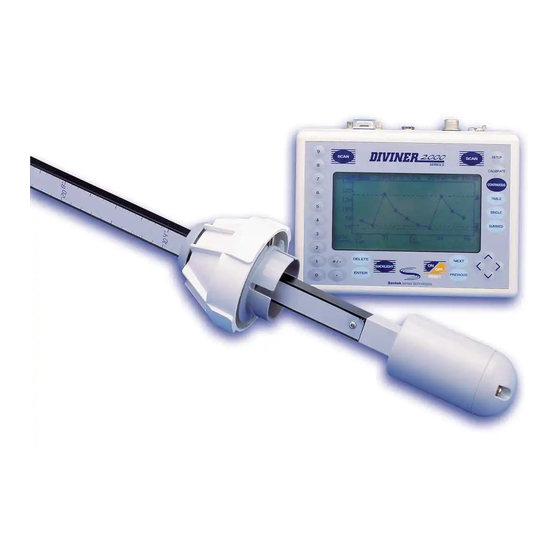
Sensor Figure 1— Components of the Diviner 2000 display unit and probe Diviner 2000 is a portable soil moisture monitoring system. It comprises a data display unit and a portable probe. The portable probe measures soil moisture content at regular intervals of 10 cm (4 inches) down through the soil profile. -
Page 9: Data Use
PC for backup farm record maintenance. Data use The Diviner 2000 display unit, the probe, the installed access tubes and the Diviner 2000 Utilities software combine to give you meaningful data on soil moisture and: •... -
Page 10: Care And Maintenance Of The Equipment
Care and Maintenance of the equipment • Contact your Sentek distributor when repairs or maintenance are needed on the Diviner 2000 equipment. Do not attempt repairs yourself. This can result in further damage being caused to the equipment and will void any Sentek warranty. -
Page 11: Storing The Diviner 2000
• Recharge the unit monthly to prevent total discharge of the battery. Repeat the charging if full charge is not achieved after the first cycle. • Fully charge the Diviner 2000 display unit prior to the first use after storage. ©Sentek Pty Ltd... -
Page 12: Part 1-The Diviner 2000 Display Unit And Probe
General description Part 1—The Diviner 2000 display unit and probe General description The Diviner 2000 display unit is a data storage, display and conversion tool. It collects and stores information for up to 99 profiles or soil monitoring sites. The display unit Figure 2—Diviner 2000 display unit... -
Page 13: Connection Panel
The probe The Probe consists of a metal rod with a probe cap and a sensor at the bottom. The connection cable from the Diviner 2000 display unit plugs in to the connector at the top end of the rod. -
Page 14: Before You Start
Charging the Diviner 2000 display unit The Diviner 2000 display unit requires charging. A 13.8V DC, 800 mA regulated power pack is supplied by Sentek Pty Ltd. Alternatively a 15V Universal (100-250V) AC Adaptor is supplied. Always charge the Diviner 2000 display unit before and after use. -
Page 15: Status Screen
Part 1—The Diviner 2000 display unit and probe Before you start Status screen Status screen is displayed when the Diviner 2000 display unit is turned on. It is a summary screen describing the current status. Figure 4—Status screen feature… means…... -
Page 16: Setup Mode
Note: The small connector does not need to be screwed in and will only fit one way. The Diviner 2000 display unit is now connected to the probe. You are now ready for setting up Diviner 2000. Setup mode mode is used to configure the Diviner 2000 display unit. -
Page 17: Setting The Time And Date
<Select mode when done> Figure 5—Setup screen Setting the time and date Diviner 2000 uses a 24-hour clock. The time and date settings indicate when a reading is taken in the field and forms part of the profile reading record. -
Page 18: Normalizing The Sensor
Part 1—The Diviner 2000 display unit and probe Setup mode 5. Enter the last two digits of the year using the numeric keypad, e.g. 99 or 00. 6. Press ENTER to save the new date setting. The cursor moves to the air count setting to begin normalizing the probe. -
Page 19: Adjusting The Vertical Scale Units (Inch, Cm)
2. Use the left/right arrow keys to select from the available options; table, single or summed, (refer to page 22). Note: Sentek recommends that you set the ‘summed’ graph as the default screen. 3. If you select None the unit will stay in Scan mode after completing a scan. -
Page 20: Adjusting The Serial Baud Rate
5. Press ENTER to save or use the arrow keys to move on to the next option. Calibrating Diviner 2000 Before you begin to use Diviner 2000 you must enter a calibration equation. Diviner 2000 does not automatically generate accurate volumetric soil water content data for all types of soils. To obtain this information you... -
Page 21: Working With The Default Calibration Equation
The default calibration equation is based on combined data gathered from sampling on sand, sandy loam and an organic potting soil. It is described in Figure 6. It is built into the Diviner 2000 display unit and is labeled as the calibration equation for soil type #01. -
Page 22: Creating A Soil Profile With The Default Calibration Equation
Part 1—The Diviner 2000 display unit and probe Calibrating Diviner 2000 Cook ≈ Raw EnviroSCAN Diviner A = 0.1957 A = 0.2746 -1000.0 B = 0.404 B = 0.3314 C = 0.02852 C= 0.0 High = 1 Low = 0 e.g. - Page 23 Alternatively the lip can be positioned 5 cm/2 inch above the soil surface. This allows the Diviner 2000 sample to be taken at 5 cm/2 inch below the soil surface rather than 10 cm/3.9 inch. This can be useful for shallow rooted crops.
-
Page 24: Working With Customized Calibration Equations
Absolute data To generate absolute data, you need to conduct gravimetric sampling to calibrate the Diviner 2000 for every soil textural layer on your property. Sentek Pty Ltd recommends that the Gravimetric sampling technique is used. It is recognized as the world standard and has been used to calibrate devices such as the Neutron Probe and TDR. -
Page 25: Measuring The Soil Moisture Content
Measuring the soil moisture content When your access tubes have been installed, you are ready to use the Diviner 2000 to measure soil moisture content. Refer to the Access Tube Installation Guide or your local distributor for details on how to install your access tubes. - Page 26 Part 1—The Diviner 2000 display unit and probe Measuring the soil moisture content To scan (swipe and go) Ø Note: The first ‘swipe and go’ at each profile determines the maximum depth for future readings. 1. Unscrew the cap on the access tube.
-
Page 27: Continuous Mode
Part 1—The Diviner 2000 display unit and probe Measuring the soil moisture content 12. Press ENTER to try again or DELETE to exit. The readings are displayed in the default screen that you selected during setup, i.e. in a summed or single, table or graph. You can view the readings in any of the four forms by pressing the TABLE, SINGLE or SUMMED mode keys. -
Page 28: Accessing Diviner 2000 Data
3. To stop recording, press CONTINUOUS or select another mode. Accessing Diviner 2000 data This section describes the data available on the Diviner 2000 display unit through the table mode, single and summed, and single graph and summed graph modes. If you interpret the data in the field, then you can take steps immediately to schedule irrigation. - Page 29 Part 1—The Diviner 2000 display unit and probe Accessing Diviner 2000 data feature… means… Data time/date time and date of data recorded Depth depth to which the soil moisture content reading refers (single table), or the total moisture content down to that depth (summed...
-
Page 30: Graphs (Single And Summed)
Part 1—The Diviner 2000 display unit and probe Accessing Diviner 2000 data 2. Press PREVIOUS. The Table mode (Single) screen displays. To set the Full, Refill and Mark points in summed table mode Ø 1. Select Profile and change if required by: •... -
Page 31: Figure 11-Single Graph Screen
Part 1—The Diviner 2000 display unit and probe Accessing Diviner 2000 data Figure 11—Single graph screen To use the single graph mode Ø 1. Press the SINGLE mode key. The date and time of data recording displays in the top right hand corner. -
Page 32: Figure 12-To Show Dashed Vertical Line
Part 1—The Diviner 2000 display unit and probe Accessing Diviner 2000 data Figure 12—To show dashed vertical line 6. Use the arrow keys to move the dashed line across to a desired data point to view further information. The exact value of the data point through which the dashed line passes displays below the x-axis. -
Page 33: Deleting Data
Note: The data values may not be displayed if they are well above or below the full or refill points. Diviner 2000 establishes a scale in relation to these points. If the data is outside this scale you will not see the data values. -
Page 34: Formatting The Diviner 2000
4. To delete continue to press DELETE twice. Formatting the Diviner 2000 Warning: Formatting the Diviner 2000 removes all setup information entered. This includes probe normalization, all profiles and their data. Please backup any data on the Diviner unit before formatting. -
Page 35: Irrigation Scheduling Using Diviner 2000 Data
Part 1—The Diviner 2000 display unit and probe Irrigation scheduling using Diviner 2000 data Formatting the Diviner 2000 Ø SET UP MODE Time (hh:mm) 01:59 23-Feb-08 Date (dd-mm-yy) 167709 Air count 124574 Water count 10cm/3.9in Probe type metric Units Summed Table... -
Page 36: Plotting Data On Your Irrigation Management Chart
This information can also be kept on your PC, using IrriMAX. A chart records three-month sets of Diviner 2000 data from one site. In this way, seasonal data can be recorded from year to year and seasonal trends can be easily identified from one sheet. -
Page 37: Other Basic Records Required For Irrigation Management
Part 1—The Diviner 2000 display unit and probe Irrigation scheduling using Diviner 2000 data 3. Fill in the year the data was taken so that you can compare the same season next year. Note: In this way you develop an irrigation management history. -
Page 38: Figure 14-Irrigation Management Chart
Part 1—The Diviner 2000 display unit and probe Irrigation scheduling using Diviner 2000 data Diviner 2000 Irrigation Management Chart Profile No ___ Site Description________________________ Irrigation Scheduling Unit________ Year ______ Crop Age ______ Crop Rootstock__________________ Soil Type _____________ Month Month Month Figure 14—Irrigation management chart... -
Page 39: How Often Should I Take Readings
Part 1—The Diviner 2000 display unit and probe Irrigation scheduling using Diviner 2000 data How often should I take readings? Review the Sentek Pty Ltd video, which came with your Diviner 2000 package. The frequency of Diviner readings determines the resolution of the soil water trends. -
Page 40: Figure 16-Soil Water Extraction Phases
Part 1—The Diviner 2000 display unit and probe Irrigation scheduling using Diviner 2000 data Soil water drying cycle over total soil water storage in Soil water attributes mm in the crop’s root zone Soil profile is saturated Phase 1 and still draining—crop... - Page 41 Part 1—The Diviner 2000 display unit and probe Irrigation scheduling using Diviner 2000 data In Phase 1 the change in volumetric soil moisture content is due to the processes of drainage and evapo-transpiration. In Phase 2 and Phase 3 the change is predominantly due to evapo-transpiration.
-
Page 42: Examples Of Data And Trend Interpretation
Part 1—The Diviner 2000 display unit and probe Irrigation scheduling using Diviner 2000 data The Onset of Crop Water Stress concept is the soil moisture content in the plant root zone when the first observable slow-down of the maximum daily crop water use rate after irrigation or rainfall occurs. -
Page 43: Figure 17-Daily Water Changes
Part 1—The Diviner 2000 display unit and probe Irrigation scheduling using Diviner 2000 data Daily soil water changes Figure 17—Daily Water changes Figure 17 (Summed Graph) shows an irrigation event followed by a staircase dynamic. The steep part of the stairs indicates soil water change during the day light hours (transpiration, and evaporation). -
Page 44: Figure 18-The Active Root Zone
Part 1—The Diviner 2000 display unit and probe Irrigation scheduling using Diviner 2000 data The active root zone Figure 18—The active root zone In Figure 18 daily changes at 10 cm, 20 cm, 30 cm and 40 cm are quite pronounced. -
Page 45: Figure 19-Onset Of Crop Water Stress
Part 1—The Diviner 2000 display unit and probe Irrigation scheduling using Diviner 2000 data The onset of crop water stress Figure 19—Onset of crop water stress Figure 19 shows the soil daily soil water change dynamics after an irrigation event. Initially the steps are relatively even indicating a non- stressed soil moisture conditions for the crop. -
Page 46: Figure 20-Root Zone Water Extraction
Part 1—The Diviner 2000 display unit and probe Irrigation scheduling using Diviner 2000 data Figure 20—Root zone water extraction Figure 20 shows root zone water extraction at the 10 cm, 20 cm, 30 cm, 40 cm, 50 cm depth level, but none at 60 cm and 70 cm. the reason for this pattern could be that the roots are: •... -
Page 47: Figure 21-Irrigating Beyond The Root Zone (Over-Irrigation)
Part 1—The Diviner 2000 display unit and probe Irrigation scheduling using Diviner 2000 data Figure 21—Irrigating beyond the root zone (over-irrigation) Figure 21 shows the same site as Figure 20. In Figure 21 the depth of the irrigation creates a dramatic increase of soil moisture content down to 70 cm soil depth. -
Page 48: Figure 22-Depth Of Irrigation Balances Soil Moisture Extraction
Part 1—The Diviner 2000 display unit and probe Irrigation scheduling using Diviner 2000 data Figure 22—Depth of irrigation balances soil moisture extraction Figure 22 shows the same site as Figures 20 and 21. Here the depth of irrigation replaces the amount of soil water extraction at the bottom of the root zone at the same magnitude as it was removed by the plant. -
Page 49: Figure 23-Full Point In Summed Graph
Part 1—The Diviner 2000 display unit and probe Irrigation scheduling using Diviner 2000 data Figure 23—Full point in summed graph Figure 23 shows in a summed form the same data as in Figure 22. The separate level data are showing an event that can be described as a good Full Point event. -
Page 50: Figure 24-Water-Logging
Part 1—The Diviner 2000 display unit and probe Irrigation scheduling using Diviner 2000 data Water-logged conditions Figure 24—Water-logging Figure 25 shows a slow down of crop water use for four days after an irrigation event. This is an example of flood irrigated cotton grown on heavy clay soils showing the symptom of water-logging. -
Page 51: Constructing Site Specific Soil Water Budgets
Now you can construct a soil water budget for optimum crop productivity. To construct a soil water budget Ø 1. Enter the Full and Refill points in your diviner 2000 display unit, and/or your irrigation management chart. 2. Ensure that soil moisture content remains between these two points (refer to Figure 22). -
Page 52: Figure 26-Soil Water Budget Trends
Part 1—The Diviner 2000 display unit and probe Irrigation scheduling using Diviner 2000 data Figure 26—Soil Water Budget trends ©Sentek Pty Ltd ACN 007 916 672 Page 46... -
Page 53: Part 2 Diviner 2000 Utilities Software
Using Diviner 2000 Utilities Diviner 2000 Utilities is a software application you can use to: • download and store data from the Diviner 2000 in a backup file • restore data from your backup files to the Diviner 2000 • prevent a Diviner downloading into an incorrect database ©Sentek Pty Ltd... -
Page 54: Installing Diviner 2000 Utilities
CSV file for use in third party applications such as spreadsheets, e.g. Microsoft Excel. For downloading the data from Diviner 2000 and restoring data to the unit a serial connection needs to be established. The export of the data to the CSV file however, does not require serial connection since it uses the backup file(s) as the source of data. -
Page 55: Starting Diviner 2000 Utilities
2000 data on a PC. From the main window you can: • backup data from the Diviner 2000 display unit to your PC • restore backed up data from your PC to the Diviner 2000 display unit • View and delete database ID tags stored on the Diviner 2000 display unit •... -
Page 56: Establishing Communications
Diviner 2000 Utilities online help file. Establishing communications The Diviner 2000 display unit is connected to your PC via a standard serial port. A successful connection requires you to configure the Diviner 2000 display unit and the Diviner 2000 Utilities software with matching communication settings. - Page 57 Part 2 Diviner 2000 Utilities software The Diviner 2000 Utilities main window Communication settings for the Diviner 2000 Utilities are configured in the Settings tab of the main window. These settings are a once-only setup. The current backup path for backup files is also defined in the Settings tab.
-
Page 58: Backing Up Diviner 2000 Data
6. Change the Diviner 2000 Utilities baud rate to match the rate selected in Step 4. Note: reduce the baud rate in the Diviner 2000 and in Diviner Utilities if the communication does not appear to be reliable. Backing up Diviner 2000 data... -
Page 59: Restoring And Exporting Data
(from the backup files) to a text based file. Restoring data to the Diviner 2000 The Diviner 2000 display unit must be connected to a serial port of the PC before data restoration can begin. See Establishing communications page 50. - Page 60 When exporting data, Diviner 2000 Utilities checks if a file already exists with the same name. If the file name exists, Diviner 2000 Utilities checks for compatible data formats, calibration data and sensor depths. If the data is compatible, only new (later in date) data is added to the appropriate file.
- Page 61 You can also double-click the line to resize the column to the minimum useable width. To restore data to the Diviner Ø 1. Prepare the Diviner 2000 display unit and Diviner 2000 Utilities software for communications as described in Establishing communications on page 50.
- Page 62 Part 2 Diviner 2000 Utilities software The Diviner 2000 Utilities main window 2. Click Export. The Export to csv dialog box displays. Source backup file name Utilities Diviner 2000 automatically creates a base name for the export file based on the backup file name.
-
Page 63: Using Esw Id Tags
• existing file has been modified manually. Using ESW ID Tags The Diviner 2000 Display Unit must be connected to the serial port of the PC before the Refresh View or Delete Selected functions will work. (See Establishing communications on page 50.) The ESW ID Tags tab is used to: •... - Page 64 The Diviner 2000 Utilities main window Finding the ESW ID Tag Ø 1. Open the IrriMAX software. (Go to Start - All Programs - Sentek - IrriMAX) 2. From a Workspace page in the IrriMAX software, select File, then Open, then Database, and browse for a database (.sdb file) that you wish match with the Diviner Display Unit.
- Page 65 Deleting ID Tags from a Diviner Ø 1. Identify the ID Tag (.ID file) to be deleted from the Diviner 2000 Display Unit as described in Finding the ESW ID Tag on page 58. 2. From the ESW ID Tags tab of Diviner 2000 Utilities, highlight the ID Tag you wish to delete from the Diviner 2000 Display Unit.
-
Page 66: Troubleshooting
5. Make sure that the baud rate for the Diviner 2000 display unit match the baud rate for the Diviner 2000 Utilities. 6. Lower the baud rate (keeping the baud rates matched) and try again. - Page 67 Troubleshooting with formatting. The Diviner 2000 data should be backed up before formatting. The steps required are describe in section Formatting the Diviner 2000 page 28. To rectify charging problems Ø Symptom Remedy Diviner 2000 display unit fails to Plug a power pack into the charging...
- Page 68 A successful scan will never occur if the probe length is shorter than the length of the profile. You must either create a new profile or use a probe of the correct length. ©Sentek Pty Ltd Page 62 ACN 007 916 672...
-
Page 69: Recommended Reading
Recommended reading Recommended reading Greacen, E L (1981); Soil Water Assessment by the Neutron; CSIRO, East Melbourne, Victoria, Australia ©Sentek Pty Ltd ACN 007 916 672 Page 63... -
Page 70: Appendix A-Theory Of Operation
The sensor operates at a very high frequency (in excess of 100 Mhz). It is not possible to tune all Diviner 2000 sensors to exactly the same raw count response when measuring a particular standard, e.g. in a water bucket. - Page 71 The capacitance technique in general has potential advantages over traditional nuclear soil moisture monitoring techniques such as the lack of random counting error, lighter equipment weights, quick responsive readings and no radioactive hazards. ©Sentek Pty Ltd ACN 007 916 672 Page 65...
-
Page 72: Appendix B-Soil Moisture Management
What does 1% or 1 mm volumetric soil moisture content/10 cm or 100 mm soil depth mean? You require one liter of water to cover one square meter (m ) to a soil depth of one millimeter. Metric units: ©Sentek Pty Ltd Page 66 ACN 007 916 672... - Page 73 Appendix B—Soil Moisture Management Imperial measurement units: What part of the soil profile does the Diviner 2000 measure? The first depth level is located at a soil depth of 10 cm (if the datum plate of the top cap sits on ground level) measuring effectively the soil profile slice of 5–15 cm depth.
- Page 74 • The total soil moisture content from 10 to 50 cm is 115 mm (Profile 1). • The total soil moisture content from 10 to 20 cm is 35 mm (Profile 2). ©Sentek Pty Ltd Page 68 ACN 007 916 672...
-
Page 75: Appendix C-Creating A Customized Calibration Equation
The distinctions must be clear. Refer to installation diagram below. 2. At each depth on the probe take three Diviner 2000 raw count readings e.g. 10cm, 20 cm, 30cm. 3. Calculate the scaled frequency for each sample. - Page 76 The mass is obtained by drying the sample at 105 C to constant weight, and the volume is the volume of the core sampler. 13. Calculate as follows: • Mw = wet mass of soil core (g) ©Sentek Pty Ltd Page 70 ACN 007 916 672...
- Page 77 You may wish to generate separate calibration equations for individual soil layers at a particular depth level. The Diviner 2000 can process data using a different calibration equation for each 10 cm depth level increment.
- Page 78 • access tube installation with air gaps and soil compactions. 4. In mathematical and statistical procedures: • errors in calculations • using unsuitable curves for the equation. ©Sentek Pty Ltd Page 72 ACN 007 916 672...
-
Page 79: Appendix D-Software License Agreement
II. OWNERSHIP AND COPYRIGHT OF SOFTWARE Licensee acknowledges that all rights, title and interest to the Software and user manual remain with Sentek. The Software and user manual are copyrighted and protected by the laws of Australia and other countries, and international treaty provisions. - Page 80 Appendix D—Software License Agreement Sentek proprietary and copyright notices and other legends in the same manner that Sentek provides such notices and legends, both in and on every copy of the Software and user manual in any form. Except as...
- Page 81 License. VII. TERM AND TERMINATION Sentek may terminate this License at any time if Licensee is in breach of any of its terms and conditions. Upon termination, Licensee will immediately destroy the Software and user manual or return all copies of the Software and user manual to Sentek.
- Page 82 If sent by registered or certified mail, postage prepaid, return-receipt requested, notice shall be deemed effective on the date the return receipt shows the notice was accepted, refused or returned undeliverable. ©Sentek Pty Ltd Page 76 ACN 007 916 672...
- Page 83 II. OWNERSHIP AND COPYRIGHT OF SOFTWARE Licensee acknowledges that all rights, title and interest to the Software and user manual remain with Sentek. The Software and user manual are copyrighted and protected by laws of the United States and other countries, and international treaty provisions.
- Page 84 Software or user manual in the performance of a contract or subcontract with a Government, prior to such use, Licensee shall consult with Sentek as to the procedures and use of restrictive markings required to protect the ownership interest of Sentek.
- Page 85 License. VII. TERM AND TERMINATION Sentek may terminate this License at any time if Licensee is in breach of any of its terms and conditions. Upon termination, Licensee will immediately destroy the Software and user manual or return all copies of the Software and user manual to Sentek.
- Page 86 If sent by registered or certified mail, postage prepaid, return-receipt requested, notice shall be deemed effective on the date the return receipt shows the notice was accepted, refused or returned undeliverable. ©Sentek Pty Ltd Page 80 ACN 007 916 672...
-
Page 87: Index
Deleting Irrigation management a data point ............27 charts..............30 a profile..............28 scheduling ............29 all data points .............28 soil moisture............29 Diviner 2000 Irrigation Management Chart ....... 2, 30 Backlight............13 battery ..............9 calibration screen..........16 charging ...............8 Function ...............6 connection panel...........7 Mode..............7 datum value ............16 Navigation............6... - Page 88 Trend interpretation ..........33 overview...............2 Troubleshooting swipe-and-go mode..........20 battery charging..........61 communication settings ........60 fatal errors ............61 RACW Readily Available Water Capacity....35 formatting Diviner 2000........60 Readings scan failures............61 first scan.............20 unlocking the display unit ........60 frequency ............2, 30 recommended frequency ........33 Recording video continuous mode..........19...
Need help?
Do you have a question about the Diviner 2000 and is the answer not in the manual?
Questions and answers