Advertisement
Quick Links
Advertisement

Related Manuals for Vincent Medical Manufacturing Inspired O2FLO

Summary of Contents for Vincent Medical Manufacturing Inspired O2FLO
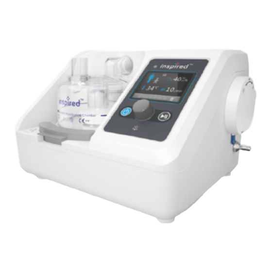
- Page 1 High Flow Heated Respiratory Humidifier USER MANUAL...
- Page 3 Medical Manufacturing Co., Ltd. Without wri�en consent, any individual or organiza�on must not copy, modify, or translate any part of this manual. Customer Service Contact Information Vincent Medical Manufacturing Co., Ltd Flat/RM B2, 7/F., Hang Fung Industrial Building, Phase 2, 2G Hok Yuen Street, Hung Hom, Kowloon, Hong Kong...
-
Page 4: Table Of Contents
TABLE OF CONTENTS Page INTRODUCTION WARNINGS AND CAUTIONS SPECIFICATION DEVICE OVERVIEW SET-UP PRE-USE CHECKS OPERATION... - Page 5 SETTINGS RECORDING OF DATA TROUBLESHOOTING MAINTENANCE EMC INFORMATION WARRANTY DEFINITION OF SYMBOLS...
-
Page 6: Introduction
flow oxygen therapy with a flow rate from 2L/min to 60L/min. INTENDED POPULATION The inspired O2FLO™ is used for infant to adult pa�ents within a hospital environment under the supervision of trained medical personnel. ADVERSE REACTIONS / RESIDUAL RISKS The following adverse events are associated with this device: Hyperthermic/Hypothermic inhala�on, Inhaled humidity deficit, Hypoxia, Barotrauma,... -
Page 7: Warnings And Cautions
WARNINGS AND CAUTIONS Safety Informa�on Symbol Defini�on WARNING Warnings alert users to hazardous situa�ons that may cause any harm to the pa�ent, end user or damage to the environment. CAUTION Cau�ons alert users to poten�ally hazardous situa�ons which, if not avoided, may result in damage to the equipment or other property. - Page 8 • To reduce the likelihood of disconnec�on and to prevent adverse device performance, use only accessories compa�ble with this device. Compa�bility is determined by reviewing the instruc�ons for use of either the device or the accessories. • Do not use sealed pa�ent interfaces(e.g. nasal mask) with this device, to avoid the risk of suffoca�on and/or barotrauma.
- Page 9 • Do not a�empt to manually fill the humidifica�on chamber with water or liquid of any kind. Doing so may flood the device leading to device malfunc�on and pa�ent injury. • This device can be used in desktop, pole-mounted and wall-mounted configura�ons.
- Page 10 • Any liquid spilled onto or entering into the device may cause damage to the device injury to pa�ent and/or end user. • Oxygen supply shall be standard dry and clean compressed oxygen for medical applica�ons. The minimum oxygen concentra�on required is 99.5%. Use of any other gas or mixture of gases will prevent the device from func�oning correctly and impair treatment.
- Page 11 • To ensure proper opera�on, and to avoid injury, do not posi�on the device so that it is difficult to disconnect the mains plug. • Do not a�empt to service the device while it is in use. Doing so may cause damage to the device or injury to pa�ent and/or end user.
- Page 12 • The device must not be used in the presence of a flammable anesthe�c mixture with air or oxygen or nitrous oxide. Doing so may lead to fire or explosion. • Use of flammable anaesthe�c mixtures with this device can lead to fire hazards. •...
- Page 13 CAUTION • The device is intended to be used in a professional healthcare facility environment e.g., hospitals, except for areas where the intensity of electromagne�c disturbances is high, e.g., near ac�ve high- frequency surgical equipment, rooms used for magne�c resonance imaging, electrophysiology laboratories, or areas where short-wave therapy equipment is used.
- Page 14 • To avoid device damage, do not place liquid containers on or near the top of the device. • If the machine is not being used for a long period of �me, it is recommended that the device is unplugged/ disconnected from the electrical outlet. •...
- Page 15 • Flowmeter used with device must be capable of delivering oxygen flow of up to 60L/min. Otherwise FiO will be limited to low levels in high Flow Rate se�ngs. • If the device is running normally without any alarm, and no ac�on has been taken for 10 minutes, the device will enter screen saver mode and display the real-�me Flow Rate, Dew Point Temperature and FiO •...
-
Page 16: Specification
SPECIFICATION SAFETY CLASSIFICATIONS • Type of protec�on against electric shocks: Class II. • Humidifier classifica�on per ISO 80601-2-74: Category 3 • Degree of protec�on against electric shock: Type BF applied parts (Pa�ents will come in direct contact with nasal cannula during treatment.) •... - Page 17 Humidifica�on Output ≥33mg/L @ 37°C ≥16mg/L @ 31 – 36°C Maximum Temperature of Delivered Gas 48°C Maximum Temperature of Accessible Surface 50°C Maximum Limited Pressure 60 hPa (60 cmH Sound Pressure Level (Acous�c Noise) ≤60dBA @ 1m Alarm Volume ≥60dBA @ 1m Dimensions 243mm x 220mm x 170mm Net Weight...
-
Page 18: Device Overview
DEVICE OVERVIEW LIST OF DEVICE COMPONENTS IMAGE DESCRIPTION inspired O2FLO™ 1 pc VUN-300 Connec�on Cable 1 pc NOTE: Referred to as CONNECTION CABLE in this manual 25 pc Filter Connec�on Tube NOTE: Referred to as 1 pc OXYGEN TUBE in this... - Page 19 LIST OF APPROVED ACCESSORIES PRODUCT NAME AND IMAGE MAXIMUM USE PERIOD 14 DAYS AUTOFEED HUMIDIFICATION CHAMBER VHC60 14 DAYS ADULT INTEGRATED BREATHING CIRCUIT 510-049 (CIRCUIT + CHAMBER KIT: 511-049-C60) 14 DAYS PAEDIATRIC INTEGRATED BREATHING CIRCUIT 510-050 (CIRCUIT + CHAMBER KIT: 511-050-C60) 1 YEAR CONNECTION CABLE VUN-300...
- Page 20 14 DAYS NASAL CANNULA VANC-01 (S) VANC-02 (M) VANC-03 (L) 7 DAYS NASAL CANNULA VINC-01 (S) VINC-02 (M) VINC-03 (L) VINC-04 (XL) 30 DAYS FILTER OXYGEN TUBE NOTE: Apart from the CONNECTION CABLE and the OXYGEN TUBE, all accessories are single use.
- Page 21 DEVICE FEATURES Gas Outlet Water Level & Filter Chamber Sensor Heater Plate Chamber Lock Oxygen Inlet Air Inlet Cap Moun�ng Plate SD Card Slot Power Cord Heater Wire Socket Temperature Probe Socket Moun�ng Bracket Connec�on Cable P/N.:10022868 Rev.A...
- Page 22 USER INTERFACE - OVERVIEW Status LED LCD Display Run time 00 00 00 00 Stand-by Bu�on Start/Pause Bu�on Control Knob Green (flashing): Connected to mains power, not yet switched on Green (con�nuous): Indicates normal opera�on Status LED Yellow (flashing): Indicates Medium Priority alarm Red (flashing): Indicates High Priority alarm Stand-by Bu�on...
- Page 23 USER INTERFACE – LIST OF SYMBOLS Part Number Name Func�on Select for Adult Mode. Adult breathing Adult Mode circuit must be used in Adult Mode. Select for Paediatric Mode. Paediatric breathing Paediatric Mode circuit must be used in Paediatric Mode. Displays oxygen concentra�on.
-
Page 24: Set-Up
SET UP Water Bag Flowmeter SD card slot Connection Heated breathing circuit cable Probe wire Heater wire Autofeed humidi cation chamber Oxygen inlet port Oxygen tube (blue) (red) NOTE: This device can be used in desktop, pole-mounted and wall-mounted configura�ons. The Moun�ng Plate on the back of device allows a�achment to the Moun�ng Bracket fixed to pole or wall. - Page 25 1. INSTALL AUTOFEED HUMIDIFICATION CHAMBER • Press down the chamber lock and install the chamber onto the heater plate. Align and fully insert the gas inlet of the chamber into the gas outlet of the device. When posi�oned correctly, the chamber lock will click into place. 2.
- Page 26 WARNING Ensure that the water level in the humidifica�on chamber is maintained below the maximum water level mark. Failure to do so may cause water to spill into the breathing circuit or the device. This may affect the quality of the therapy and injure the pa�ent.
- Page 27 • Align the insert guide and insert the other end of the Connec�on Cable into the Heated Breathing Circuit. Ensure plug is fully inserted. 5. ATTACH OXYGEN TUBE • Connect one end of the OXYGEN TUBE to the outlet nozzle of the flow meter by pushing the tube on firmly.
- Page 28 6. SELECT NASAL CANNULA • Select the correct nasal cannula for use. ATTENTION: Fit the nasal cannula to the pa�ent but do not connect the nasal cannula to the circuit un�l the device has finished warming up. Ensure the device is delivering desired levels of flow rate, dew point temperature and FiO before connec�ng to the nasal cannula.
-
Page 29: Pre-Use Checks
PRE-USE CHECKS CHECK FILTER The device contains a filter which is located in the air inlet on the side of the device. The filter should be replaced with a new one at least once every 30 days in single pa�ent use, or a�er every pa�ent. -
Page 30: Operation
OPERATION 1. POWER-ON SELF-TEST • Press and hold the stand-by bu�on ( for 2 seconds to turn on the device. • During self-test, the screen on the right will be displayed. • Check that the status LED lights up in red, green, and yellow sequen�ally during self-test. - Page 31 • Block the pa�ent connec�on port of the breathing circuit �ghtly. Pre-Use Test • Press the control knob to start the Chamber installed pre-use test. The device will go through Water level detection the 4 steps sequen�ally. The blower will Connection cable installed Leakage check run during the test.
- Page 32 Message displayed Correc�ve ac�on • Ensure the chamber is posi�oned correctly. Chamber installed • Ensure the drip line of the chamber is connected to a sterile water source hung above. • Ensure the drip tube is free of kinks or blockages Water level detection and that there is sufficient water in the water bag.
- Page 33 3. OPERATING SETTINGS – ADULT/ PAEDIATRIC MODE • Use the control knob to unlock the screen by scrolling over and selec�ng the lock icon ( Screen is unlocked when the icon is displayed as ( • To switch between Adult Mode and Paediatric Mode, rotate the control knob to highlight the mode icon ( ) and press the control knob.
- Page 34 5. OPERATING SETTINGS – FLOW RATE • Use the control knob to scroll to the Flow Rate display ( • Press the control knob to highlight then rotate to reach desired se�ng. Press control knob again to confirm input. • The Flow Rate can be adjusted within the following ranges. Dew Point Temperature Range Adult Mode 10 –...
- Page 35 WARNING Con�nuous monitoring of blood oxygen concentra�on of the pa�ent is required while using this device. Failure to do so could lead to pa�ent injury. 7. RUN DEVICE • Press the Start/Pause bu�on ( ) to begin running. • The device will begin to warm up and respiratory gases will begin to flow at the desired rate.
- Page 36 • FiO level below or equal to 25% will be displayed as 21%. FiO level above 95% will be displayed as 100%. • When oxygen supply is not connected to the device, please keep the cap of the oxygen inlet port closed. •...
- Page 37 10. BEGIN TREATMENT • Once the device is running and the desired Flow Rate, Dew Point Temperature and FiO se�ngs have been reached, the pa�ent can be connected to the device. • Connect the circuit to the nasal cannula. 11. PAUSING TREATMENT •...
- Page 38 NOTE: • If FiO is above 25%, the window on the right will appear. Ensure oxygen is • Supply of oxygen must be turned off before not flowing the device can stop running. FiO2: 54% • Once FiO falls below 25%, the device can enter Cooling Down phase or shut down.
- Page 39 SETTINGS • Time, language, and volume se�ngs can be changed, and device history informa�on can be accessed through the se�ngs menu when the device is not in use. • Use the control knob to unlock the device, then scroll to the SETTINGS icon ( •...
- Page 40 3. VOLUME SETTINGS • Use the control knob to scroll to the VOLUME icon ( Language Info • Press the control knob to highlight volume Time level and rotate control knob to adjust. Op. Time History • Press the control knob again to select desired volume level.
- Page 41 5. OPERATION TIME • Use the control knob to scroll to OP. TIME. Operation Time • Press the control knob to enter the Opera�on Time page. 0001 • The cumula�ve opera�on �me (when blower is running) of the device is shown. 6.
- Page 42 ALARM INFORMATION • The inspired O2FLO is equipped with an alarm indicator light, auditory alarm signal and on-screen informa�on signal to warn about interrup�ons to pa�ent treatment. All alarms are technical alarm condi�ons. • When an alarm is triggered, the LED will flash in red or yellow, and an audible alarm will sound.
- Page 43 Medium Priority Alarms E1 Oxygen sensor failure E2 Flow sensor failure E4 Heater plate temp. Replace CONNECTION CABLE or CIRCUIT sensor failure Power off the device and restart. E5 Cooling fan failure System Failure If the error persists, make a note of E6 Turbine failure (E#) the fault code and contact VM or...
- Page 44 ADULT MODE selected when PAEDIATRIC CIRCUIT is connected, or Incompa�ble Ensure that the CIRCUIT matches the vice versa. circuit type mode selected for use. NOTE: May take up to 15 seconds to alarm Check the CANNULA or CIRCUIT if it is bent, kinked or blocked.
- Page 45 Ensure that ambient temperature is within the range specified in this IFU A�er warm up, chamber (18 - 28°C). outlet dew point temperature con�nuously If temperature is low, decrease the differs by more than ±2°C device flow rate. Temp. from the temperature out of range If temperature is high, increase the specified by user.
- Page 46 FUNCTIONAL TEST FOR FLOW RATE ALARM The func�onality of the “Flow out of range” alarm condi�on can be checked at any �me when the device is running. To check this, set the flow rate to 10L/min and run the device. Restrict the opening of the pa�ent connec�on port of the breathing circuit, such that the actual flow rate achieved by the device is 6 –...
- Page 47 RECORDING OF DATA SD CARD The device contains a removable SD card which records real �me usage data such as �me stamped alarm history and se�ngs adjustments. The SD card can be removed by pressing it in to ac�vate the release spring. ATTENTION: •...
- Page 48 ACCESSING ALARM HISTORY AND USAGE DATA • Insert the SD card into a computer and run the installer (O2FLO Data Reader.msi). • Once installed, run the Vincent Medical Data Reader so�ware (O2FLO.exe). The following window will be displayed. Language Help Import data Time Setting Export data...
- Page 49 ACCESSING OPERATION LOG • The opera�on log records every change in device se�ngs, as well as the start and end �me of every alarm condi�ons. It can be accessed through LogReader.exe. LogReader About Equipment Info Model: Software Ver: Top Page Pre Page Next Page End Page...
- Page 50 TROUBLESHOOTING SYMPTOM POSSIBLE CAUSE REMEDIATION Power cable is not securely Securely plug the power cable plugged into mains power. into mains power. LED light does not light up Contact professional Equipment failure. maintenance personnel. The gas path is blocked, circuit Check the pa�ent interface and No flow detected or cannula is bent or blocked.
- Page 51 MAINTENANCE Refer maintenance and servicing to qualified service personnel. The technical descrip�on is contained in O2FLO Maintenance Manual. WARNING • Do not a�empt to service the device while it is in use. Doing so may cause damage to the device or injury to pa�ent and/or end user. •...
- Page 52 VISUAL INSPECTION The device should be properly maintained throughout its expected service life. Visual inspec�on of the following parts should be conducted on a monthly basis, by trained technical personnel familiar with the technical performance of the inspired O2FLO™ and any damaged or faulty parts should be replaced immediately: •...
- Page 53 EMC INFORMATION The O2FLO is designed to comply with the electromagne�c compa�bility (EMC) requirements of IEC 60601-1-2. It is suitable for the electromagne�c environment of typical commercial, hospital or domes�c establishments. During the immunity tes�ng specified in IEC 60601-1-2, the O2FLO con�nued to generate and deliver a flow of warmed and humidified gas, and monitored the oxygen concentra�on of the gas flow.
- Page 54 • Avoid exposure to known sources of EMI (electromagne�c interference) such as Magne�c Resonance Imaging (MRI) systems, diathermy, lithotripsy, electrocautery, RFID (Radio Frequency Iden�fica�on), and electromagne�c security systems such as an�-the�/electronic ar�cle surveillance systems, metal detectors. Note that the presence of RFID devices may not be obvious. If such interference is suspected, reposi�on the device, if possible, to maximize distances.
- Page 55 WARRANTY Do not a�empt to disassemble the device without authoriza�on. The warranty period is 2 years from the date of purchase. For shelf-life of accessories please refer to the appropriate manual. Warranty is considered void under the following condi�ons: • An error caused by opera�ng the device in a non-prescribed condi�on or applica�on •...
- Page 56 DEFINITION OF SYMBOLS Refer to instruc�on manual Consult instruc�ons for use Cau�on Non-sterile Do not use if package Do not re-use is damaged Date of manufacture Manufacturer Use by date Serial No. Batch code Catalogue number Authorized representa�ve Cau�on, hot surfaces in the European Community Par�culate ma�er and drip Alterna�ng current...
- Page 57 Dew Point Temperature Oxygen Concentra�on (FiO Flow Rate Alarm Audio Paused at aiarm condi�on SD Card No SD Card Se�ngs Back Lock/Unlock...
- Page 60 Customer Service Contact Information Vincent Medical Manufacturing Co., Ltd Flat/RM B2, 7/F., Hang Fung Industrial Building, Phase 2, 2G Hok Yuen Street, Hung Hom, Kowloon, Hong Kong Customer Service Hotline Tel: +852 2186 1010 Email: service@inspired-medical.com Website: www.inspired-medical.com...
Need help?
Do you have a question about the Inspired O2FLO and is the answer not in the manual?
Questions and answers