Table of Contents
Advertisement
Quick Links
Advertisement
Table of Contents

Related Manuals for Vicpas FLI-150


Summary of Contents for Vicpas FLI-150
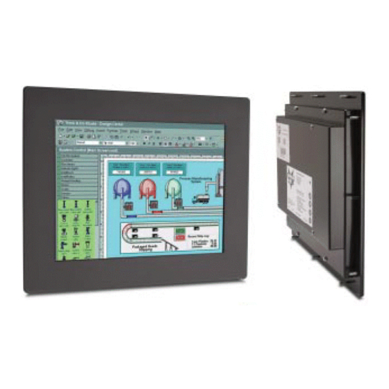
- Page 1 FLI-150 FLI-150-TS LCD Monitor User Guide Revised 12/02...
-
Page 2: Table Of Contents
FLI-150 & FLI-150-TS Table Of Contents Section 1 Introduction About LCD Monitors Product Safety Precautions Section 2 Display Setup Included Parts Connecting Your Display Section 3 Getting Started Display Features Getting Started Adjusting the Display Using the Auto-Adjust OSD (On Screen Display) Adjustments... -
Page 3: Section 1 Introduction
Introduction Section About LCD Monitors What you gain by using an LCD monitor for your industrial display is the future of display technology. CRTs although they have dropped in cost significantly, do not offer the performance, reliability, and mounting options available with LCDs. LCD monitors consist primarily of an LCD, video board and a backlight. - Page 4 Safety Precautions CAUTION: SHUT OFF YOUR TOUCH SCREEN BEFORE CLEANING!! IF YOUR DISPLAY IS A –TS MODEL, THAT IS A TOUCH SCREEN DISPLAY, THE SCREEN WILL BE ACTUATED BY CLEANING. PRESSING ON THE SCREEN WHILE CLEANING WILL BE SEEN AS A TOUCH TO THE SYSTEM WHICH COULD CREATE A POTENTIALLY DANGEROUS CONDITION!! Do not attempt to service this display yourself.
-
Page 5: Section 2 Display Setup
Input Signal” message on the screen, your computer or video source may be putting out a signal that is incompatible with the FLI-150(-TS). If this happens, reboot the computer with the previous display and adjust the display settings to be within the FLI-150(-TS) specifications (see Appendix C). -
Page 6: Display Features
The FLI-150(-TS) is capable of displaying 16M (24 Bit) colors in a continuous spectrum. The high contrast LCD enhances the image with no geometric distortion. FLI-150(-TS) Series directly accepts an analog 3,4, or 5 wire RGB with separate H/V, composit, or sync on green. This is the standard PC video signal. -
Page 7: Using The Auto-Adjust
Using the Auto-Adjust The FLI-150(-TS) will attempt to adjust itself to your computers current video mode. If the picture is stable, and centered vertically and horizontally the auto-adjustment is complete. If however the picture is not stable, and centered vertically and horizontally you can re-initate the auto adjustment. - Page 8 PICTURE Press MENU key to bring up the OSD. Press UP/DOWN key, to move between the 5 primary screen functions. Press the Select button at Picture, to select it. Press the UP/DOWN key, you can now move between functions and press Select to adjust the value of each item with the UP/DOWN key.
-
Page 9: Introduction To Touch Screens
The FLI-150(-TS) touch screen interface, is a high resolution, analog resistive. Following is a quick explanation of what all this means. High Resolution: The touch screen resolution is 400 ppi [points per inch] Analog Resistive: The actual touch glass is an analog device. - Page 10 Touch Screen Driver Installation for Windows 98 Required items to know or have to install the Touch Driver. What Operating System you are using. Windows 98 What Serial Port you are connected to. Usually COM 1 or COM 2 The type of touch screen. Smartset The CD-ROM or Floppy disk included with the system.
-
Page 11: Windows Nt
Touch Screen Driver Installation for Windows NT 4.0 Required items to know or have to install the Touch Driver. What Operating System you are using. Windows NT 4.0 What Serial Port you are connected to. Usually COM 1 or COM 2 The type of touch screen. - Page 12 Touch Screen Driver Installation for Windows 2000 Required items to know or have to install the Touch Driver. What Operating System you are using. Windows 2000 What Serial Port you are connected to. Usually COM 1 or COM 2 The type of touch screen. Smartset The CD-ROM or Floppy disk included with the system.
-
Page 13: Windows Xp
Touch Screen Driver Installation for Windows XP Required items to know or have to install the Touch Driver. What Operating System you are using. Windows XP What Serial Port you are connected to. Usually COM 1 or COM 2 The type of touch screen. Smartset The CD-ROM or Floppy disk included with the system. -
Page 14: Section 5 Mounting Instructions
Mounting Instructions Section Panel Mounting Procedure 1. Cut and drill the panel (refer to Figure 2; Panel Mount Drawing Appendix D). Measurements are in inches. A template of the hole pattern has been supplied with your monitor to assist in making the mounting holes accurately. Also, there is an AutoCad .dxf file included on the provided CD. - Page 15 Troubleshooting Tips Section No Picture Check that the signal cable is properly connected to the display. Try disconnecting the video cable from the display and connecting to another display if available to confirm the presence of proper video. Make sure power is connected to a proper DC source and that the AC supply to the DC source is ON.
- Page 16 Green LED not lit Check for proper power and power connections Display image is not properly sized Press the “Select” button to Auto Adjust the display Adjust the Vertical and Horizontal size controls via the OSD. (Reference setup adjustments) Ensure that a supported mode is selected on the display card or system being used.
- Page 17 Cleaning & Maintenance Section Cleaning CAUTION: SHUT OFF YOUR TOUCH SCREEN BEFORE CLEANING!! IF YOUR DISPLAY IS A –TS MODEL, THAT IS A TOUCH SCREEN DISPLAY, THE SCREEN WILL BE ACTUATED BY CLEANING. PRESSING ON THE SCREEN WHILE CLEANING WILL BE SEEN AS A TOUCH TO THE SYSTEM WHICH COULD CREATE A POTENTIALLY DANGEROUS CONDITION!! Occasionally clean the display panel and cabinet with a soft cloth dampened (not soaked) with a mild (non-abrasive) glass cleaner.
-
Page 18: Section 8 Appendices
Appendices Section Appendix A – Video Pin Assignments Pin assignments for the HD15 video connector Pin 1 Red Video Pin 9 No Connection Pin 2 Green Video Pin 10 Sync Ground Pin 3 Blue Video Pin 11 Not Used Pin 4 Not Used Pin 12 Bi-Directional Data... - Page 19 Appendix C –General Specifications FLI-150 & FLI-150-TS Active Screen Area 11.97" x 8.98" Brightness Contrast 300:1 Lamp Life Screen Resolutions VGA-SXGA Native Resolution (Best Picture) View Angle L / R 70/70 View Angle Up / Dn 55/65 Voltage 12 VDC Current Draw 2.0a / 12 VDC...
- Page 20 Appendix D – Mounting Dimentions...
- Page 22 NOTES Model Number: _________________ Serial Number: _________________...
Need help?
Do you have a question about the FLI-150 and is the answer not in the manual?
Questions and answers