Table of Contents
Advertisement
Quick Links
Operation/Repair/Parts
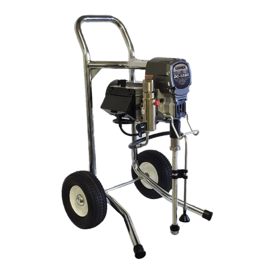
DC-5550
Electric Airless Sprayers
For professional use only.
Not approved for use in explosive atmospheres and hazardous locations.
For the application of architectural paints and coatings.
3300 psi (22.7 MPa, 227 bar) Maximum Working Pressure
Important Safety Instructions
Read all warnings and instructions in this manual and in related manuals.
Be familiar with the controls and the proper usage of the equipment.
Save these instructions.
CALGARY
•
TORONTO
•
MONTRÉAL
Advertisement
Table of Contents

Subscribe to Our Youtube Channel
Related Manuals for Lemmer DC-5550


Summary of Contents for Lemmer DC-5550
- Page 1 Operation/Repair/Parts DC-5550 Electric Airless Sprayers For professional use only. Not approved for use in explosive atmospheres and hazardous locations. For the application of architectural paints and coatings. 3300 psi (22.7 MPa, 227 bar) Maximum Working Pressure Important Safety Instructions Read all warnings and instructions in this manual and in related manuals.
- Page 2 Warnings Warnings The following warnings are for the setup, use, grounding, maintenance, and repair of this equipment. The exclamation point symbol alerts you to a general warning and the hazard symbols refer to procedure-specific risks. When these symbols appear in the body of this manual or on warning labels, refer back to these Warnings.
- Page 3 Warnings SKIN INJECTION HAZARD High-pressure spray is able to inject toxins into the body and cause serious bodily injury. In the event that injection occurs, get immediate surgical treatment. • Do not aim the gun at, or spray any person or animal. •...
- Page 4 Warnings EQUIPMENT MISUSE HAZARD Misuse can cause death or serious injury. • Always wear appropriate gloves, eye protection, and a respirator or mask when painting. • Do not operate or spray near children. Keep children away from equipment at all times. •...
- Page 5 Warnings MOVING PARTS HAZARD Moving parts can pinch, cut, or amputate fingers and other body parts. • Keep clear of moving parts. • Do not operate equipment with protective guards or covers removed. • Pressurized equipment can start without warning. Before checking, moving, or servicing equipment, follow the Pressure Relief Procedure and disconnect all power sources.
-
Page 6: Hi-Boy Models
Component Identification Hi-Boy Models Trigger Lock ON/OFF Switch M Drain Tube Pressure Control Fluid Intake Two-Finger Trigger Conversion Kit Pump Prime Valve Fluid Outlet Tip Guard Filter Spray Tip Finger Guard / TSO Fill Point Pail Hook Airless Hose Model/Serial Tag (Not shown, located Power Cord on bottom of unit.) -
Page 7: Power Requirements
Grounding Grounding The equipment must be grounded to reduce the risk of static sparking and electric shock. An electric or static spark can cause fumes to ignite or explode. An improper ground can cause electric shock. A good ground provides an escape wire for the electric current. -
Page 8: Pressure Relief Procedure
Pressure Relief Procedure Pressure Relief Procedure Turn pressure control to lowest setting. Follow the Pressure Relief Disengage the trigger lock. Procedure whenever you see this symbol. This equipment stays pressurized until pressure is manually relieved. To help prevent serious injury from pressurized fluid, such as skin injection, splashed fluid and moving parts, follow the Pressure Relief Procedure whenever sprayer is... -
Page 9: Trigger Lock
Pressure Relief Procedure Trigger Lock Put drain tube in a pail. Turn prime valve down. Leave prime valve in down (drain) position until you are ready to spray Always engage the trigger lock when sprayer again. is stopped to prevent the gun from being triggered accidentally by hand or if dropped or bumped. - Page 10 Setup Setup Use wrenches to tighten securely. Engage trigger lock. When unpacking sprayer for the first time or after long term storage perform setup procedure. When first setup is performed remove shipping plug from fluid outlet. Connect airless hose to fluid outlet. Use wrenches to tighten securely.
- Page 11 Setup When unpacking sprayer for the first Make certain ON/OFF switch is OFF. time remove packaging materials from inlet strainer. After long term storage check inlet strainer for clogs and debris. Plug power supply cord into a properly grounded electrical outlet. Fill throat packing nut with TSO to prevent premature packing wear.
- Page 12 Setup 10. Turn prime valve down. 15. Turn prime valve horizontal. Disengage trigger lock. ti29641a 11. Place fluid intake with drain tube in grounded metal pail partially filled with flushing fluid. See Grounding NOTE: New sprayers are shipped with storage fluid that must be flushed out with mineral spirits prior to using the sprayer.
- Page 13 Startup Startup Turn pressure control 1/2 turn to start motor. Allow paint to circulate through sprayer until paint flows out the drain tube. Perform Pressure Relief Procedure Turn pressure control to lowest pressure. 15 s Turn prime valve horizontal. Disengage trigger lock.
- Page 14 Startup Hold gun against grounded metal waste pail. Trigger gun until paint appears. High-pressure spray is able to inject toxins into the body and cause serious bodily injury. Do not stop leaks with hand or rag. Inspect for leaks. If leaks occur, perform Pressure Relief Procedure then tighten all fittings and repeat Startup procedure.
-
Page 15: Operation
Operation Operation Spray Tip Installation Spray Spray test pattern. Adjust pressure to eliminate heavy edges. To avoid serious injury from skin injection do not put your hand in front of the spray tip when installing or removing the spray tip and tip guard. -
Page 16: Clear Tip Clog
Operation Clear Tip Clog NOTE: If spray tip is difficult to rotate when turning to the unclog position, perform In the event that particles or debris clog the Pressure Relief Procedure, then spray tip, this sprayer is designed with a turn Prime/Spray valve to spray position and reversible spray tip that quickly and easily repeat step 1. -
Page 17: Digital Display
Operation Digital Display Press and hold display button to change pressure units (psi, bar, or MPa). Some models are equipped with a digital display. This section explains how to use this feature. Pressure Display 1. Perform Pressure Relief Procedure Plug sprayer into grounded outlet. Turn ON/OFF switch to ON position. - Page 18 Operation Sprayer model number is displayed To erase last error code, press and hold followed by Data Point 1 which is the unit display button. power on time in hours. Press display button again to display Data Point 4. The software revision is displayed.
- Page 19 Operation Cleanup Place fluid intake in flushing fluid. Use water for water base paint and mineral spirits for oil-based paint. Place drain Perform Pressure Relief Procedure tube in waste pail. Remove tip guard and Spray Tip. For additional information, see separate gun manual.
- Page 20 Operation Stop triggering gun. Move gun to waste Raise fluid intake above flushing fluid. pail, hold gun against pail, trigger gun to thoroughly flush system. While continuing to trigger gun, turn prime valve down. Then, release gun trigger. Allow flushing fluid to circulate until fluid comes out of drain tube clear.
- Page 21 Operation 11. Engage trigger lock. 14. If flushing with water, flush again with mineral spirits or Pump Conditioner to leave a protective coating to prevent freezing or corrosion. 12. Turn pressure control knob to the lowest pressure setting and turn ON/OFF switch to OFF position.
-
Page 22: Maintenance
Maintenance Maintenance Routine maintenance is important to ensure proper operation of your sprayer. Maintenance includes performing routine actions which keep your sprayer in operation and prevents trouble in the future. Activity Interval Inspect/clean sprayer filter, fluid inlet strainer, and gun Daily or each time you spray filter. -
Page 23: Troubleshooting
Troubleshooting Troubleshooting Mechanical/Fluid Flow Follow Pressure Relief Procedure Check all possible problems and causes before checking or repairing. before disassembling the unit. What to Check What to Do If check is OK, go to next When check is not OK, Problem check refer to this column... - Page 24 Troubleshooting What to Check What to Do If check is OK, go to next When check is not OK, Problem check refer to this column Pump output is low Pump rod damage. Repair pump. See pump manual. Low stall pressure. Turn pressure knob fully clockwise.
- Page 25 Troubleshooting What to Check What to Do If check is OK, go to next When check is not OK, Problem check refer to this column Fluid is spitting from gun Air in pump or hose. Check and tighten all fluid connections.
- Page 26 Troubleshooting Electrical View digital display or remove control box cover to view control board status light. To determine which code (or any Symptom: Sprayer does not run, stops other code besides voltage supply) refer running, or will not shut off. to the control board status light.
- Page 27 Troubleshooting Problem What to Check How to check Check transducer or transducer Sprayer does not run at all Make sure there is no pressure in the system (see Pressure Relief connections Procedure . Check fluid Display shows E=02 path for clogs, such as clogged filter. Use airless paint spray hose with no metal braid.
- Page 28 Troubleshooting Problem What to Check How to check Sprayer does not run at all Check voltage supply to the sprayer Turn ON/OFF switch OFF and (control board is detecting a multiple disconnect power to sprayer. voltage surges). Locate a good voltage supply to Display shows E=04 prevent damage to electronics.
- Page 29 Troubleshooting Problem What to Check How to check 6.Connect the Red and Black leads from the motor to an Ohm meter. Rotate the motor while checking for opens. If an open is found replace the motor. BLACK (-) RED (+) YELLOW 1-3 ohms 7.Check motor thermal protection.
- Page 30 Troubleshooting Problem What to Check How to check 8.Use an Ohm meter to check motor for shorts. Connect (–) meter lead to motor case. Move the (+) meter lead to each motor wire. Meter should read open on all wires. GROUND BLACK YELLOW...
- Page 31 Troubleshooting Problem What to Check How to check Basic electrical problems Motor leads are securely fastened Replace loose terminals; crimp to and properly mated leads. Be sure terminal are firmly connected. Clean circuit board terminals. Securely reconnect leads. For loose motor brush lead Tighten terminal screws.
- Page 32 Troubleshooting Sprayer Will Not Run (See following page for steps) Remove Control box cover. Turn sprayer ON. Observe control board status light on See Step 1. Do you control board have over 100 VAC No Light Once Normal Operation See Step 2. Do you have over 100 VAC Control board Light on...
- Page 33 Troubleshooting Step 1: Step 3: Plug Power cord in and turn Check motor thermal switch. switch ON. Connect probes Unplug yellow wires. Meter to L and N on control board. should read continuity. Turn meter to AC Volts. NOTE: Motor should be cool during reading.
- Page 34 Troubleshooting Sprayer Will Not Shut Off Remove control box cover so the control board status light can be viewed Perform Pressure Relief Procedure, if available. Leave prime valve open (down) and turn ON/OFF switch OFF. Troubleshooting Procedure Plumb pressure gauge into paint hose, Mechanical problem: plug sprayer in, and turn power switch ON.
-
Page 35: Technical Specifications
Technical Specifications Technical Specifications Technical Specifications Displacement Pump Metric Maximum fluid working pressure 3300 psi 227 bar, 22.7 MPa Inlet/Outlet Sizes Fluid inlet size 1.0 in. diameter Fluid outlet size 1/4 in. Wetted materials on all models stainless steel, PTFE, leather, nylon, zinc-plated and nickel-plated carbon steel, tungsten carbide, chrome plating, UHMWPE, acetal, polyethylene, nylon... - Page 36 Fluid Pump Parts...
- Page 37 Fluid Pump Parts Ref. Part Description Qty. Ref. Part Description Qty. 125724 V-PACKING, piston, 2 17J183 SEAT, top (piston) KIT, rod, piston V-Max 17P096 Quick Repair, pump UHMWPE 176755 V-PACKING, leather 17P095 , pump 17J188 GLAND, male, pis- 180656 PLUG, button ton, lower 17J184 V-PACKING, throat, 176754 GLAND, male, throat,...
-
Page 38: Hi-Boy Sprayers
Hi-Boy Sprayers Hi-Boy Sprayers Ref. Torque 30-35 in-lb (3.4 - 4.0 N•m) - Page 39 Hi-Boy Sprayers Ref. Torque 140-160 in-lb (15.8 - 18.1 N•m) 30-35 in-lb (3.4 - 4.0 N•m) Hammer tight 25-30 ft-lb (33.8 - 40.6 N•m)
-
Page 40: Hi-Boy Sprayers Parts List
Hi-Boy Sprayers Hi-Boy Sprayers Parts List Ref. Part Description Qty. Ref. Part Description Qty. MOTOR, includes 54a, 107434 BEARING, thrust 116073 WASHER, thrust 287015 120V 116074 WASHER, thrust 116079 BEARING, thrust 54a 118716 RING, retaining 117501 SCREW, mach, hex 54b 248189 FAN, motor, includes washer hd 103413... -
Page 41: Control Box
Control Box Control Box Ref. Torque 140-160 in-lb (15.8 - 18.1 N•m) 30-35 in-lb (3.4 - 4.0 N•m) 20-25 in-lb (2.3 - 2.8 N•m) 37-43 ft-lb (50.2 - 58.3 N•m) 130-150 in-lb (14.7 - 16.9 N•m) -
Page 42: Control Box Parts List
Control Box Control Box Parts List Ref. Part Description Qty. Ref. Part Description Qty. BOX, control 117828 PACKING, o-ring 276868 555/5150 models 111457 PACKING, o-ring 111600 PIN, grooved CONTROL, board 277364 GASKET, seat, valve 555/5150 models: 115494 SCREW, mach, 246379 120V Phillips, pan hd 115498... -
Page 43: Wiring Diagrams
Wiring Diagrams Wiring Diagrams 120V Black ON/OFF Black Switch Power Plug Black White Green Red (+) Black (-) from Motor Digital Display 2 x White... - Page 44 Technical Specifications Technical Specifications DC-5550 Metric Sprayer Maximum fluid working pressure. 3300 psi 228 bar, 22.8 MPa Maximum Delivery (DC5550) 0.54 gpm 2.0 lpm Maximum Tip Size (DC5550) 0.023 0.023 Fluid Outlet npsm 1/4 in. 1/4 in. Cycles 700 per gallon...
- Page 45 (caractéristiques sont sujets à changement sans prévis) LEMMER PAINT SPRAYING EQUIPMENT LIMITED WARRANTY LEMMER Spray Systems Ltd. extends to the original purchaser of its paint spray equipment a limited one year warranty from the date of purchase against defects in material or workmanship provided that the equipment is installed and operated in accordance with the recommendations and instructions written in the owners manual.
Need help?
Do you have a question about the DC-5550 and is the answer not in the manual?
Questions and answers