Table of Contents
Advertisement
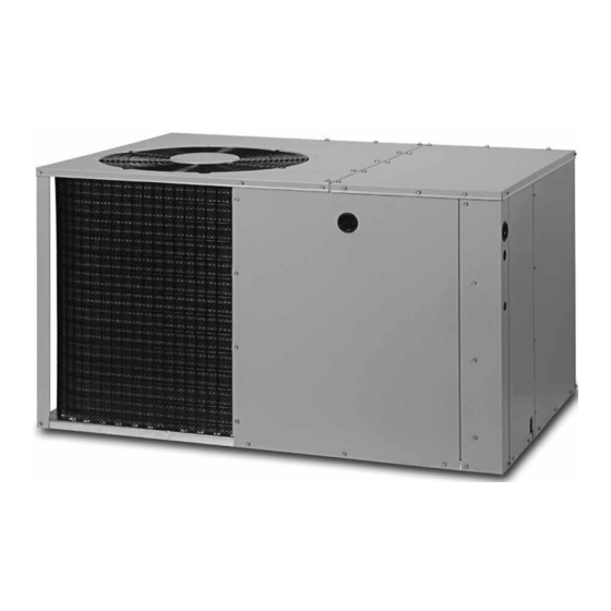
*Q7RE SERIES
INSTALLATION INSTRUCTIONS
Single Package Heat Pump - Single Stage, R-410A
It is your responsibility to know this product better than your customer. This includes being
able to install the product according to strict safety guidelines and instructing the customer on
how to operate and maintain the equipment for the life of the product. Safety should always be
the deciding factor when installing this product and using common sense plays an important
role as well. Pay attention to all safety warnings and any other special notes highlighted in the
manual. Improper installation of the furnace or failure to follow safety warnings could result in
serious injury, death, or property damage.
These instructions are primarily intended to assist qualified individuals experienced in the
proper installation of this appliance. Some local codes require licensed installation/service
personnel for this type of equipment. Please read all instructions carefully before starting the
installation. Return these instructions to the customer's package for future reference.
DO NOT DESTROY. PLEASE READ CAREFULLY & KEEP IN A SAFE PLACE FOR FUTURE REFERENCE.
IMPORTANT
ATTENTION INSTALLERS:
14 SEER
Advertisement
Table of Contents

Subscribe to Our Youtube Channel
Related Manuals for ACPro VQ7RE


Summary of Contents for ACPro VQ7RE
- Page 1 *Q7RE SERIES 14 SEER INSTALLATION INSTRUCTIONS Single Package Heat Pump - Single Stage, R-410A IMPORTANT ATTENTION INSTALLERS: It is your responsibility to know this product better than your customer. This includes being able to install the product according to strict safety guidelines and instructing the customer on how to operate and maintain the equipment for the life of the product.
-
Page 2: Table Of Contents
TABLE OF CONTENTS IMPORTANT SAFETY INFORMATION .....3 STARTUP & ADJUSTMENTS ........10 Pre-Start Checklist ..........10 REQUIREMENTS & CODES ........4 Start-Up Procedure ..........10 GENERAL INFORMATION ........4 Air Circulation ............10 Before You Install this Unit ........4 System Heating ............10 Locating the Heat Pump ..........4 System Cooling ............10 Minimum Clearances ..........4 Short Cycle Protection .........10... -
Page 3: Important Safety Information
IMPORTANT SAFETY INFORMATION CAUTION: Please read all instructions before servicing this equipment. Pay attention to all safety warnings and any other special notes This unit uses R-410A refrigerant. DO NOT use highlighted in the manual. Safety markings are used frequently any other refrigerant in this unit. -
Page 4: Requirements & Codes
REQUIREMENTS & CODES area where they will be shaded from the afternoon sun, when the heat load is greatest. • All electrical wiring must be completed in accordance with • Consideration should also be given to availability of electric local, state & national codes and regulations and with the power, service access, noise, and shade. -
Page 5: Air Duct System
Air Duct System HEAT PUMP INSTALLATION Air ducts should be installed in accordance with the standards of Unpacking the Unit the National Fire Protection Association “Standard for Installation It is recommended that the unit be unpacked at the installation of Air Conditioning and Ventilation Systems” (NFPA 90A), site to minimize damage due to handling. -
Page 6: Return Duct
2. After measuring the return air box (approximately 12-1/4” x 20-1/4”), cut the hole through the floor so that the box will fit between the floor joists. Care should be taken when cutting through carpeting to avoid snags. NOTE: In most installations it will be necessary to cut a similar hole in the fiberboard directly under the hole in the floor. -
Page 7: Electrical Connections
ELECTRICAL CONNECTIONS WARNING: ELECTRICAL SHOCK, FIRE OR EXPLOSION HAZARD Failure to follow safety warnings exactly could result in serious injury or property damage. Improper servicing could result in dangerous operation, serious injury, death or property damage. • Before servicing, disconnect all electrical power to the indoor blower. -
Page 8: Overcurrent Protection
lighting fixtures, and convective heat from warm air registers or CAUTION: electrical appliances. Refer to the thermostat manufacturer’s instruction sheet for detailed mounting information. Label all wires prior to disconnection when Defrost Control Board Test Pins servicing controls. Wiring errors can cause •... -
Page 9: Ambient Sensor Mounting
HEAT RISE DATA (BASED ON NOMINAL 10KW ELECTRIC HEAT KIT) EXTERNAL STATIC PRESSURE DROP - INCHES WATER COLUMN MODEL BLOWER NUMBER SETTING HEAT HEAT HEAT HEAT HEAT HEAT HEAT HEAT RISE RISE RISE RISE RISE RISE RISE RISE Tap T1* Tap T2 1158 1119... -
Page 10: Startup & Adjustments
4. Set the temperature mode below room temperature. Verify STATUS STATUS DIAGNOSTIC that the indoor blower, outdoor fan, and compressor energize INDICATOR TYPE DESCRIPTION and the cooling function starts. Operating Status Cooling, 1st Stage 5. Verify the discharge air grilles are adjusted and the system Operating Status Heating, 1st Stage air is balanced. -
Page 11: Anti Short Cycle Timer Test
Anti Short Cycle Timer Test • Inspect and clean or replace air filters at the beginning of each The 5 minute time delay feature can be bypassed by shorting heating and cooling season, or more frequently if required. the TEST pins together. •... -
Page 12: Refrigerant Charging Tables - Cooling
Refrigerant Charging Tables - Cooling NOTES: LEGEND Shaded boxes indicate flooded conditions. 1. All pressures are listed psig and all temperatures in °F Rated design values. The suction pressure will vary 2. Discharge temperatures greater than charted values indicate from design value if outdoor air flow, entering dry bulb, an undercharged system. - Page 13 LEGEND NOTES: Shaded boxes indicate flooded conditions. 1. All pressures are listed psig and all temperatures in °F Rated design values. The suction pressure will vary 2. Discharge temperatures greater than charted values indicate from design value if outdoor air flow, entering dry bulb, an undercharged system.
- Page 14 LEGEND NOTES: Shaded boxes indicate flooded conditions. 1. All pressures are listed psig and all temperatures in °F Rated design values. The suction pressure will vary 2. Discharge temperatures greater than charted values indicate from design value if outdoor air flow, entering dry bulb, an undercharged system.
-
Page 15: Refrigerant Charging Tables - Heating
Refrigerant Charging Tables - Heating LEGEND • All pressures are listed psig and all temperatures in °F Shaded boxes indicate flooded conditions. Rated design values. NOTE: 024K SERIES OUTDOOR TEMPERATURE (° F) Table 9. Charging Table for 2 Ton Models 030K SERIES OUTDOOR TEMPERATURE (°... - Page 16 LEGEND • All pressures are listed psig and all temperatures in °F Shaded boxes indicate flooded conditions. Rated design values. NOTE: 042K SERIES OUTDOOR TEMPERATURE (°. F) Table 12. Charging Table for 3.5 Ton Models 048K SERIES OUTDOOR TEMPERATURE (° F) Table 13.
-
Page 17: Figures & Tables
FIGURES & TABLES View 1.75 Ø Electric Heater Power Supply 1.125 Ø Power Supply 0.875 Ø Low Voltage Supply Side View Control Blower Access Panel Access 17.86 Panel 15.36 10.10 1" 3/4" NPT Drain Connection 1.38 18.01 3” 3.2 5.29 12.13 Opening for Alternate Power... -
Page 18: Wiring Diagrams
Wiring Diagrams Figure 10. W.D. for 2 & 2.5 Ton Models... - Page 19 Figure 11. W.D. for 3, 3.5 & 4 Ton Models...
- Page 20 Figure 12. W.D. for 5 Ton Models...
- Page 21 Typical Wiring for 1-Stage Cool / Heat, 1 Stage Electric Heat For HUD applications Remove white wire between terminal W2 INDOOR and W2 IN terminal TERMINAL *HUD DEFROST Outdoor BOARD Thermostat BROWN ORANGE JUMPER W2 IN W2 OUT For HUD applications move the white jumper wire from W2 terminal and connect to W2 IN terminal ACCESSORY HEAT PLUG...
-
Page 24: Installation Checklist
INSTALLATION CHECKLIST ELECTRICAL SYSTEM INSTALLATION ADDRESS: Electrical connections tight? CITY: STATE: Line voltage polarity correct? Rated Voltage: UNIT MODEL #: L1-L2 Voltage: Has the thermostat been calibrated? UNIT SERIAL #: Is the thermostat level? Unit Installed Minimum clearances Is the heat anticipator setting correct? Figure 1 (page INSTALLER NAME: REFRIGERATION SYSTEM...
Need help?
Do you have a question about the VQ7RE and is the answer not in the manual?
Questions and answers