Advertisement
Quick Links
Total solder points: 186
Difficulty level:
Beginner 1o 2þ 3o 4o 5o Advanced
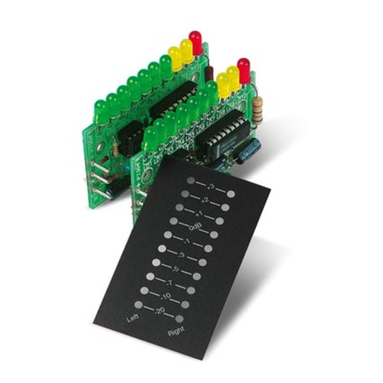
2 x 10 LED STEREO VU METER
• For instant visualization of audio signal levels.
• Easy hook up to a LINE level ( LOW input) signal source.
• For use with mixing panels, amplifiers, CD players, radio's, ...
• A special input (HIGH INPUT) is provided, which allows direct con-
nection to a SPEAKER* output .
• DOT or BAR display mode selectable to suit your application.
• Attractive display window supplied, which can be used both horizontal
as vertical.
• If wanted, the unit can be calibrated by means of a trim potentiometer.
*NOT SUITED FOR CONNECTION TO HIGH POWER CAR STEREO
SYSTEM
Specifications:
• 2 X 10 LED's
• BAR OR DOT MODE
• INDICATION RANGE: 0dB = 0.775mVrms.
-20dB, -10dB, -7dB, -5dB, -3dB, -1dB, 0dB, +1dB, +2dB, +3dB
• FREQUENCY RANGE: 20Hz tot 30KHz
• LOW INPUT FOR 0dB: 150mV to 6Vrms (47K)
• HIGH INPUT FOR 0dB: 1.5V to 60Vrms (470K).
• POWER SUPPLY: 10 to 15VDC / 250mA max.
• PCB DIMENSIONS 2X: 68X37mm
modifications reserved
PARTLIST
K4305
H4305P-ED1
Advertisement

Related Manuals for Velleman-Kit K4305

Summary of Contents for Velleman-Kit K4305
- Page 1 Total solder points: 186 Difficulty level: Beginner 1o 2þ 3o 4o 5o Advanced K4305 2 x 10 LED STEREO VU METER • For instant visualization of audio signal levels. • Easy hook up to a LINE level ( LOW input) signal source.
- Page 2 COLOR= 2… 5 4K7= ( 4 - 7 - 2 - B ) 4K7= ( 4 - 7 - 0 - 1 - 1 ) KLEUR CODICE CODIGO CODIGO VÄRI FÄRG FARVE FARGE FARB COLOUR CODIFI- CODE CATION KODE SCHEMA COLORE KOODI KODE...
-
Page 3: Assembly Steps
__________________________________________________________________________________________________________________________________________________________ ASSEMBLY STEPS Required tools to assemble the kit: A small soldering iron of max. 40W. Thin (1mm) solder, do not use any flux. A small cutter to trim the excess wires. Mount the compo- Obtain cone- shaped, This solder joint Trim the excess nents against the shiny soldered joints... -
Page 4: Zener Diodes
_______________________________________________________________________________________________________________________________________________________ Assembly Mount all components onto the PC boards (mount the two boards) 1. JUMPERS 2. DIODES (Check the polarity) D... CATHODE q D1: 1N4148 q D2: 1N4148 q D3: 1N4000… 1N4007 q J1 3. ZENER DIODES q J2, mount for BAR mode, do (Check the polarity) not mount for DOT mode. - Page 5 __________________________________________________________________________________________________________________________________________________________ 4. ¼W RESISTORS 6. RESISTOR TRIMMERS R... RV... q RV1: 220K (250K) q R1: 47K (4-7-3-B) q R2: 47K (4-7-3-B) 7. CAPACITORS q R3: 330 (3-3-1-B) q R4: 10K (1-0-3-B) C... q R5: 10K (1-0-3-B) q R6: 2K2 (2-2-2-B) q R7: 470K (4-7-4-B) q C1: 220nF (0.22µF, 224) 5.
- Page 6 _______________________________________________________________________________________________________________________________________________________ 9. 1W RESISTORS R... q R8: 68 (6-8-0-B)
- Page 7 __________________________________________________________________________________________________________________________________________________________ 10. MOUNT THE LEDs, BEND THE LEADS CAREFULLY (Check the polarity) SOLDER SIDE COLOR = 2...5 LD... CATHODE q LD1: green (5) q LD2: green (5) q LD3: green (5) q LD4: green (5) q LD5: green (5) q LD6: green (5) q LD7: green (5) q LD8: yellow (4) q LD9: yellow (4)
- Page 8 _______________________________________________________________________________________________________________________________________________________ 11. Insert the IC’s in the socket (Check the position of the notch) PIN 1 IC... q IC1: 741 q IC2: LM3916 Mount the units in a suitable housing or on a suitable panel: 12. Mounting possibility: A. Make or search for suitable bracket:...
-
Page 9: Front Panel
__________________________________________________________________________________________________________________________________________________________ B. Make the holes in the housing or panel and mount the bracket: Ø3.5 10mm M3 COUNTERSUNK-HEAD BOLT 2...3mm FRONTPANEL FRONTPANEL LOCK WASHER M3 NUT BRACKET BRACKET LOCK WASHER M3 NUT... - Page 10 _______________________________________________________________________________________________________________________________________________________ C. Mount the PCB’s with spacers onto the bracket: M3 NUT LOCK WASHER FRONTPANEL 15mm SPACER 15mm SPACER BRACKET 40mm M3 BOLT 2...3mm FRONTPANEL SOLDER BRACKET SIDE 40mm M3 BOLT M3 NUT 15mm SPACER LOCK WASHER 15mm SPACER...
- Page 11 __________________________________________________________________________________________________________________________________________________________ Connect the unit to a suitable signal, this can be line level (LOW input) : 13. Connecting to a line level output (tuner, preamp, cd player… ) and connecting a power supply from 10 to 15VDC / 250mA max.. LEFT HIGH IN LOW IN...
- Page 12 _______________________________________________________________________________________________________________________________________________________ Connect the unit to a speaker output (HIGH input): 14. Connecting to a speaker level output and connecting a power supply from 10 to 15VDC / 250mA max.. HIGH IN LEFT LOW IN P4304 SPEAKER LEFT INPUT (0) RIGHT HIGH IN SPEAKER RIGHT LOW IN...
- Page 13 __________________________________________________________________________________________________________________________________________________________ Connect the unit to a car radio: 15. Connecting to a speaker output from a regular car radio. LEFT HIGH IN LOW IN P4304 LEFT SPEAKER RIGHT HIGH IN RIGHT SPEAKER LOW IN +12V ANTENNE POWER OUT P4304 CAR RADIO The 12VDC car battery power or car radio antenna output can be used to supply the VU meter.
- Page 14 _______________________________________________________________________________________________________________________________________________________...
Need help?
Do you have a question about the K4305 and is the answer not in the manual?
Questions and answers