Table of Contents
Advertisement
Quick Links
Advertisement
Table of Contents

Related Manuals for SAFWAY Huennebeck MANTO G3

Summary of Contents for SAFWAY Huennebeck MANTO G3
- Page 1 MANTO ® Large-frame panel formwork User guide...
-
Page 2: Table Of Contents
Contents Contents MANTO formwork ....................5 Intended use ...........................5 General information .......................5 General safety information ....................6 About this user guide ......................7 Other relevant documents ....................8 Overview ........................10 Quick reference guide ....................12 Panels ............................12 3.2 Corners ..........................22 3.3 Connectors ........................... 26 3.4 Brackets and platforms ...................... - Page 3 MANTO® Using the MANTO Aligning Panel Clamp, ties and MANTO Panels 2.70 m ..82 8.2 Using the MANTO Aligning Panel Clamp, ties and MANTO panels 3.30 m ..86 8.3 With the PLATINUM 100 Extension Bar ................. 93 8.4 Using MANTO Aligning Panel Clamp, ties and MANTO XXL panels ....95 Tying .........................
- Page 4 Contents 17.1 Assembling formwork with one-sided tie system .............194 17.2 Assembling formwork with conventional tie method ..........202 Stripping ........................205 Cleaning on-site ....................206 20 Storage and transport ..................207 20.1 MANTO panels ........................207 20.2 Corners ..........................209 20.3 Shaft formwork ........................212 20.4 Other components ......................214 Disposal ........................217 Technical data ......................217 22.1 Permitted fresh concrete pressure for MANTO ............
-
Page 5: Manto Formwork
MANTO® MANTO formwork MANTO formwork from Hünnebeck is rugged, ready-to-use frame panel formwork for all fields of concrete construction. All MANTO panels have sturdy 14 cm thick steel frame profiles that are hot dip galvanized on the inside and outside. The maximum fresh concrete pressure permitted is 80 kN/m². -
Page 6: General Safety Information
MANTO formwork General safety information Important information regarding the intended and safe use of MANTO formwork • Risk assessment The contractor is responsible for the preparation, documentation, implementation and revision of a risk assessment for each construction site. His employees are obliged to implement the resulting measures in accordance with all legal requirements. -
Page 7: About This User Guide
MANTO® About this user guide This user guide contains important information regarding the assembly and use of Hünnebeck MANTO formwork as well as safety procedures that are important for safe use on site. This user guide is intended to serve as an aid to working effectively with MANTO formwork. -
Page 8: Other Relevant Documents
MANTO formwork 1.4.3 Brand names The following brand names are the property of Hünnebeck. The symbol indicating reg- istered trademark is omitted throughout the document. • HÜNNEBECK® • EUROPLUS® • Ecoply® • MANTO® • PLATINUM® • PROTECTO® Other relevant documents This user guide describes the safe use and operation of the MANTO system. Please also observe and comply with the information and instructions contained in the follow- ing documents pertaining to specific components: The PROTECTO edge protection user guide... - Page 9 MANTO® Unless stated otherwise, all dimensions are given in mm.
-
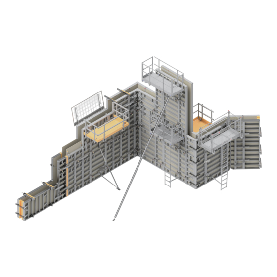
Page 10: Overview
Overview Overview Crane Transport Hook (Refer to page 207) Pouring Platform (Refer to page 171) Counter Post (Refer to page 170) and Walkway brackets (Refer to page 168) Height extensions (Refer to page 79) Infills (Refer to page 75) (Refer to page 97) Stopends (Refer to page 137) Alignment Struts PLATINUM 100... - Page 11 MANTO® The assembly shown is for illustration pur- PLATINUM 100 platform system poses only. Not all components are shown. (Refer to page 166) All local requirements and regulations are to be complied with. Connecting panels (vertically) (Refer to page 81) PLATINUM 100 Lifting Device (Refer to page 195) Universal Formwork Platform (Refer to page 167)
-
Page 12: Quick Reference Guide
Quick reference guide Quick reference guide MANTO panels have either an 18 mm form sheet made of birch plywood coated with phenolic resin or a 19 mm Ecoply full plastic form sheet. Panels with an Ecoply form sheet are marked as such in the following list. Panels Component Part code... - Page 13 MANTO® Component Part code Weight [kg] MANTO G3 M Panel 240/330 Ecoply (7.92 m 607820 441.42 2400 MANTO G3 M Panel 240/330 (7.92 m 609250 447.15 Generation 3 Like the MANTO G3 Giant Panels 240/330, but with 2no. centre profiles. 3300 With 2no. tie holes per tie position. Suitable for use with one-sided tie systems.
- Page 14 Quick reference guide Component Part code Weight [kg] MANTO G3 Panel 120/330 Ecoply (3.96 m 608015 198.86 MANTO G3 Panel 105/330 Ecoply (3.47 m 608020 181.75 MANTO G3 Panel 90/330 Ecoply (2.97 m 608025 164.74 MANTO G3 Panel 75/330 Ecoply (2.48 m 608030 141.79 MANTO G3 Panel 60/330 Ecoply (1.98 m 608040 124.43...
- Page 15 MANTO® Component Part code Weight [kg] MANTO Giant Panel 240/270 (6.48 m 534990 319.39 2400 Generation 2 With 4no. tie holes per tie position. This allows 1no. MANTO Giant Panel to be used with 2no. opposing panels with a width of 2700 1.20 m each. Also available with the Ecoply full plastic form sheet (19 mm).
- Page 16 Quick reference guide Component Part code Weight [kg] MANTO Panel 120/270 (3.24 m 446000 162.61 MANTO Panel 105/270 (2.84 m 446022 149.31 MANTO Panel 90/270 (2.43 m 446033 120.08 MANTO Panel 75/270 (2.03 m 446044 106.73 MANTO Panel 60/270 (1.62 m 446055 93.35 MANTO Panel 45/270 (1.22 m 450786 80.11 MANTO Panel 30/270 (0.81 m...
- Page 17 MANTO® Component Part code Weight [kg] MANTO G3 M Panel 120/270 Ecoply (3.24 m 607870 204.45 MANTO G3 M Panel 90/270 Ecoply (2.43 m 607880 163.67 MANTO G3 M Panel 60/270 Ecoply (1.62 m 607890 121.01 MANTO G3 M Panel 120/270 (3.24 m 609255 206.77 MANTO G3 M Panel 90/270 (2.43 m 609256...
- Page 18 Quick reference guide Component Part code Weight [kg] MANTO G3 Panel 120/120 Ecoply (1.44 m 608095 82.90 MANTO G3 Panel 105/120 Ecoply (1.26 m 608100 73.14 MANTO G3 Panel 90/120 Ecoply (1.08 m 608105 69.49 MANTO G3 Panel 75/120 Ecoply (0.90 m 608110 58.61 MANTO G3 Panel 60/120 Ecoply (0.72 m 608120 51.30...
- Page 19 MANTO® Component Part code Weight [kg] MANTO Panel 240/120 (2.88 m 446066 131.90 MANTO Panel 240/90 (2.16 m 479194 107.85 MANTO Panel 240/60 (1.44 m 453437 83.88 2400 Generation 2 Range of extension panels that can be used as height extensions or as independent elements for smaller heights.
- Page 20 Quick reference guide Component Part code Weight [kg] MANTO MP Panel 75/330 (2.48 m 533561 151.50 MANTO MP Panel 75/270 (2.03 m 454340 123.30 MANTO MP Panel 75/120 (0.90 m 454946 67.23 Generation 2 Multi-purpose panels with a horizontal tie hole grid. The 50 mm tying increments allow even the most difficult of formwork tasks to be accom- 3300 plished.
- Page 21 MANTO® Component Part code Weight [kg] MANTO Panel 240/270 L (6.48 m 600860 423.48 MANTO Panel 360/270 XL (9.72 m 600861 616.78 MANTO Panel 480/270 XXL (12.96 m 600862 810.29 Generation 2 MANTO XXL panels. These panels can be used in vertical or hori- 2700 zontal orientation;...
-
Page 22: Corners
Quick reference guide 3.2 Corners Component Part code Weight [kg] MANTO Inner Corner 35/330 (2.31 m 525851 113.80 MANTO Inner Corner 35/270 (1.89 m 535001 94.46 MANTO Inner Corner 35/120 (0.84 m 535012 45.86 Generation 2 This 90° Inner Corner is equipped with a releasing aid to shutter rectangular inner cor- ners. - Page 23 MANTO® Component Part code Weight [kg] MANTO Hinged Corner 35/330 532188 135.39 MANTO Hinged Corner 35/270 534588 112.07 MANTO Hinged Corner 35/120 534577 54.26 Generation 2 Flexible 350 mm wide corner panels for inner corners with angles from 60° to 175°. 3300 2700 Use PLATINUM Universal Connectors or Panel...
- Page 24 Quick reference guide Component Part code Weight [kg] MANTO Outer Corner 330 534040 84.10 MANTO Outer Corner 270 462358 69.30 MANTO Outer Corner 120 462222 31.40 Generation 2 Used as an outer corner. The legs are 100 mm long. Also used in shaft formwork with Hinged Cor- ners.
- Page 25 MANTO® Component Part code Weight [kg] MANTO Corner Adjustment 5/330 530156 32.50 MANTO Corner Adjustment 5/270 450606 20.40 MANTO Corner Adjustment 5/120 450617 11.90 Generation 2 The Corner Adjustment is used for adapting differing wall dimensions in corners and T-wall connections.
-
Page 26: Connectors
Quick reference guide 3.3 Connectors Component Part code Weight [kg] MANTO Aligning Panel Clamp 448000 5.50 The MANTO Aligning Panel Clamp ensures that joints are closed securely and the panels are properly connected and aligned without offset, all in one process. This applies to both horizontal and vertical MANTO Panel connections. - Page 27 MANTO® Component Part code Weight [kg] PLATINUM 100 Bulkhead Clamp 604328 11.02 The tension-resistant Bulkhead Clamp is used to create a stopend without any addi- tional anchors or other components, e.g. – using timber beams and a form sheet. 1108 Safe Working Moment (M): 5.00 kNm SWL (N): 36.00 kN SWL (V): 36.00 kN...
- Page 28 Quick reference guide Component Part code Weight [kg] Multipurpose Waler 100 450764 13.10 The Multipurpose Waler 100 spans length adjustments and transfers the loads into the MANTO panels. It is fastened with 2no. 1000 Multi Bolts or Waler Spanners. The result is a panel connection that is resistant to ten- sion.
- Page 29 MANTO® Component Part code Weight [kg] Tension Nut (DW 15) 197332 0.65 Used in conjunction with the Waler Spanner and the Multi Bolt. SWL (N): 40.00 kN. Refer to page 142. MANTO MP Bolt 454442 0.80 MANTO MP Nut 454670 0.34 For connecting MANTO MP panels when used as column formwork.
-
Page 30: Brackets And Platforms
Quick reference guide 3.4 Brackets and platforms Component Part code Weight [kg] MANTO P-Walkway Bracket 606240 11.92 Used to install a 900 mm wide platform. Simply attach the Walkway Bracket at the 1070 required height to the MANTO Panel by inserting the pins into a rib of the panel and securing with the Spring Pin. - Page 31 MANTO® Component Part code Weight [kg] PROTECTO Mesh Panel 263 601231 22.20 PROTECTO Mesh Panel 240 604730 20.14 PROTECTO Mesh Panel 180 604731 15.31 PROTECTO Mesh Panel 130 604733 11.09 Mesh panel, 1.15 m high, to be used along with PROTECTO Railing Posts. Allows Rail- ing Posts to be spaced up to 2.40 m apart.
- Page 32 Quick reference guide Component Part code Weight [kg] Counter Post 600814 9.20 The Counter Post is hooked to the upper horizontal rib of the panel and secured with the attached spring pin. Installation is sim- ilar to the Walkway Bracket. The Counter Post can be fastened to panels lying flat 1625 when an additional Waler Bolt D20 is used.
- Page 33 MANTO® Component Part code Weight [kg] Platform Beam 350 - 400 410931 122.20 Platform Beam 300 - 350 410920 108.80 Platform Beam 250 - 300 410910 95.40 Platform Beam 200 - 250 410909 82.00 Platform Beam 150 - 200 410894 68.60 Platform Beam 125 - 150 410883...
-
Page 34: Struts And Props
Quick reference guide 3.5 Struts and props Component Part code Weight [kg] MANTO Alignment Strut 565103 23.30 The Alignment Strut is used to brace and align formwork no higher than 3.90 m. Each Alignment Strut must be ordered with a MANTO Strut Connector or a MANTO Strut Head. - Page 35 MANTO® Component Part code Weight [kg] Alignment Strut K440 601208 23.42 Minimum extension: 3.25 m: SWL (N): 20.00 kN. Including Adapter for Alignment Struts (3.35 m): SWL (N): 19.20 kN. Maximum extension: 4.40 m: SWL (N): 11.00 kN. Including Adapter for Alignment Struts (4.50 m): 601210 35.79 SWL (N): 9.90 kN.
- Page 36 Quick reference guide Component Part code Weight [kg] Alignment Strut Super 10 602095 84.03 Minimum extension: 7.05 m: SWL (N): 27.00 kN. Including Adapter for Alignment Struts (7.15 m): SWL (N): 27.00 kN. Maximum extension: 10.25 m: SWL (N): 22.30 kN. Including Adapter for Alignment Struts (10.35 m): SWL (N): 18.30 kN.
- Page 37 MANTO® Component Part code Weight [kg] Counter Nut A/DB 260/300 107107 0.92 For EUROPLUS 260, 300 DB/DIN, EUROPLUSnew 20-250, 20-300, EUROPLUSnew 30-150 = 15.0 kN* Counter Nut AS/DB 350/410 107118 1.00 perm For EUROPLUS 350 DB/DIN, EUROPLUSnew 20-350, 20-400, EUROPLUSnew 30-250, 30-300, 30-350 Counter Nut EC 350/DB 450 562051 1.50...
- Page 38 Quick reference guide Component Part code Weight [kg] BKS Strut Connector 482008 9.10 Must be used with BKS props longer than 8.00 m. For each connection 2no. M20x40 Bolts and Nuts as well as 1no. M20x80 Bolt and Nut are required. SWL (N): 34.00 kN. Right Spindle Piece 524700 4.70...
-
Page 39: Tying Components
MANTO® 3.6 Tying components Component Part code Weight [kg] MANTO Front Tie Nut 607230 2.18 Part of the one-sided tie system. SWL (N): 90.00 kN MANTO Rear Tie Nut 607240 2.11 Part of the one-sided tie system. SWL (N): 90.00 kN MR Tie Rod DW 15 607250 1.71 Special tie rod for one-sided tying of... - Page 40 Quick reference guide Component Part code Weight [kg] Tie Nut DW 20/150 531481 1.51 Easy to fasten tie nut to be used with Tie Rods DW 20. SWL (N): 150.00 kN. Plate 8/8 400214 0.40 Used to allow the lower tie to be installed along with a Hexagonal Nut 15/50 in panels lying on the ground.
- Page 41 MANTO® Component Part code Weight [kg] Tie Equipment DW 20 100** 534213 4.10 1000 1300 Tie Equipment DW 20 130** 534224 4.80 Tie rod with a captive Tie Nut 150. SWL (N): 150.00 kN. Not for rental. Ø DW20 PLATINUM 100 Tie Rod G2 606340 3.90 The PLATINUM 100 Tie Rod G2, used with...
- Page 42 Quick reference guide Component Part code Weight [kg] MANTO Taper Tie DW 15 100 608330 2.10 Can be used with the MANTO G3 Seal- ing Insert (code:607925) without the Tie Sleeve. Refer to page 97. MANTO Taper Tie DW 20 100 608331 3.60 MANTO Taper Tie DW 20 115 608332 4.60 Can be used with the MANTO G3 Seal-...
- Page 43 MANTO® Component Part code Weight [kg] FU Tightener 568357 3.60 Used in conjunction with the Punched Steel Tape to tie across foundation formwork. SWL (N): 12.00 kN. 568081 17.20 Punched Steel Tape 25.00 m The FU Tightener and the Punched Steel Tape are used together in foundation form- work.
-
Page 44: Accessories
Quick reference guide Accessories Component Part code Weight [kg] MANTO Add-on Piece 450157 1.55 With integrated nailing strip: for on-site extensions of up to 300 mm with 21 mm plywood. Each MANTO Add-on Piece is connected with a Panel Clamp. Triangular Column Fillet 270 544952 1.40 Triangular Column Fillet 330... -
Page 45: Lifting Accessories
MANTO® 3.8 Lifting accessories Component Part code Weight [kg] MANTO Crane Adapter 446710 14.27 The Crane Adapter is attached to the edge profiles of the MANTO Panels. It is equipped with a self-locking safety catch. approx. SWL (N): 10.00 kN. Always comply with the separate operating instructions for the MANTO Crane Adapter! PLATINUM 100 Lifting Device 606920 27.99... -
Page 46: Fasteners
Quick reference guide Component Part code Weight [kg] Hook Template 548700 23.64 Used to check the operating conditions of the MANTO Crane Adapter. MANTO G3 Lifting Pin Gauge 608329 Used to check the operating conditions of the MANTO G3 Lifting Pin. 3.9 Fasteners Component Part code... -
Page 47: Transport Equipment
MANTO® 3.10 Transport equipment Component Part code Weight [kg] Euro Trolley 607610 39.57 Used to manually manoeuvre approved Hünnebeck transport equipment. The Euro Trolley has 2no. lockable swivel castors. 1225 Working load: 1300 kg Refer to page 214. Euro Lattice Box 548480 68.76 Lattice box used to store and transport small items by crane. - Page 48 Quick reference guide Component Part code Weight [kg] Uni Mesh Panel Rack 605558 65.74 Rack used to store and transport by crane up to 50no. Universal Mesh Panels 1239 Can be moved using the Euro Trolley. Working load: 1050 kg. Refer to page 214. 1170 1230 PROTECTO Mesh Panel Rack...
-
Page 49: Manto Panels
MANTO® MANTO panels The dimensions and possible combinations of the panels assure an accurate fit of the MANTO formwork to the structure to be formed. The geometry and the profiles are similar for all panels. The panels have continuous edge profiles and perforated rib profiles positioned in 300 mm increments. The corner of the panels, the area most severely stressed, is stiffened by a corner plate. -
Page 50: Manto Panels G2
MANTO panels 4.2 MANTO panels G2 MANTO panels G2 can be identified by the following characteristics: • Reinforcement plates on the inner side of the long edge profiles near the tie hole On panels 2.70 m high and ≥ 1.05 m wide and On panels 3.30 m high and ≥... - Page 51 MANTO® Ø14 mm holes in the corner plates. Reinforcement plates Tie position on the long No stiffener elements on the inside of the long edge profile without between ribs and/or be- edge profile, near the tie smaller ancillary holes tween ribs and smaller holes.
- Page 52 MANTO panels Tie opening 24(28*) MANTO G2 ~Ø27 ~Ø29 Edge profile Rib profile: All holes Ø 22 mm 2400 *Uppermost tie position with MANTO Panels 330 and 120 2400 1340 Inner corner 1200 1106 2700 1640 3300 1200 1200 1050 Unless stated otherwise, all dimensions are given in mm.
-
Page 53: Manto Panels G3
MANTO® 4.3 MANTO panels G3 MANTO panels G3 can be identified by the following characteristics: • No reinforcement plates on the inner side of the long edge profiles near the tie hole • Tie position on the long edge profile with smaller holes above and below the tie hole, for the single-side operated anchors • Bracing between ribs and/or between ribs and smaller edge profiles (in most panels). - Page 54 MANTO panels 3no. slots in the corner plates and hole Ø 21. Thus easy to recognise in a stack. No reinforcement plates Tie position on the Stiffener elements on the inner side of the long edge profile with between ribs and/or be- long edge profile near smaller ancillary holes tween ribs and smaller the tie holes.
- Page 55 MANTO® Tie opening with MANTO G3 DW Insert 29.5 MANTO G3 Ø27 Edge profile Ø33.5 29.5 Rib profile: All holes Ø 22 mm 2400 2400 1340 1200 Inner corner 29.5 1200 1100 2700 1640 3300 29.5 1200 1200 1050 Unless stated otherwise, all dimensions are given in mm.
-
Page 56: Manto Panels G3 M
MANTO panels 4.4 MANTO panels G3 M MANTO panels G3 M can be identified by the following characteristics: MANTO G4 Overview (1 : 30) • Centre profile(s) on all panels with tie positions (with smaller holes above and below the tie hole, for the single-side operated ties); • Long edge profiles without tie positions (some panels with tie position on the smaller edge profile) and no reinforcement plates;... - Page 57 MANTO® Stylised M in the corner plates and hole Ø 21. Thus easy to recognise in a stack. Centre profile with tie Long edge profiles Stiffener elements positions with small- without tie positions or between ribs and/or be- er holes above and reinforcement plates.
- Page 58 MANTO panels Tie opening with MANTO G3 DW Insert MANTO G3 M Ø27 Centre profile Ø33.5 2400 1200 H-rib (C-profile and Z-profile) All holes Ø 22 2400 1200 H-rib with Z-profile (identical dimensions) Inner corner 29.5 1200 1100 3300 29.5 640.5 2700 1640...
-
Page 59: Rules For Using Manto Panels Of Different Generations
MANTO® 4.5 Rules for using MANTO panels of different generations It is essential to follow these rules when using MANTO panels of different generations in the same formwork: • All panels must be able to withstand the same fresh concrete pressure. Pay particular attention to the reduced concrete pressure permitted for MANTO Panels G1 (refer to page 49). -
Page 60: Examples Of The Connection Of Manto Panels Of Different Generations
MANTO panels 4.6 Examples of the connection of MANTO panels of different generations The following illustrations show examples of panels connected to one another using the MANTO Aligning Panel Clamp. The panels shown here can also be connected with the PM Aligning Wedge Clamp (potentially using a different position). The uppermost tie position on MANTO Panels 330 is needed only when panels are stacked. - Page 61 MANTO® MANTO G3 M MANTO G3 M Unless stated otherwise, all dimensions are given in mm.
-
Page 62: Tie Pattern
MANTO panels Tie pattern Example: MANTO G3 M, stacked 1200 2700 1200 2400 2400 2400 Example: MANTO G3 and MANTO G3 M in the inner corner G3 M G3 M 2700 1200 2400 1200 Unless stated otherwise, all dimensions are given in mm. -
Page 63: Connecting Panels Horizontally
MANTO® Connecting panels horizontally MANTO panels are normally connected to one another using the MANTO Aligning Panel Clamp or the PM Aligning Wedge Clamp. The Adjustable Aligning Clamp or the Multipurpose Waler 100 has to be used for infills at the vertical joint. Check that all connectors are tight and, if necessary, retighten before every use and every time they are moved. -
Page 64: Using The Manto Aligning Panel Clamp
Connecting panels horizontally 5.2 Using the MANTO Aligning Panel Clamp The MANTO Aligning Panel Clamp can be used for all vertical and horizontal panel joints. The MANTO Aligning Panel Clamp, with its aligning profile of 630 mm, provides an absolutely tight, flush-mounted and perfectly aligned panel joint when it is used cor- rectly. - Page 65 MANTO® Tie position MANTO Align- ing Panel Clamp MANTO Ratchet code:408780 2700 approx. 2170 Step 1 If possible, mount MANTO Aligning Panel Clamps near the ties at the edge profiles of the panel frame. The supporting surfaces of the MANTO Aligning Panel Clamps should have full contact with the ribs of the panel.
- Page 66 Connecting panels horizontally Typical arrangements The following illustrations show typical connecting arrangements between MANTO Panels when joining panels side-by-side. For clarity, a legend of the components used is shown below. Legend MANTO Aligning Panel Clamp (code:448000) or PM Aligning Wedge Clamp MANTO Tie Nut (code: 464600) or Tie Nut 150 (code:531481) Formwork height: 0.30 m to 1.20 m 300 - 1200...
-
Page 67: With The Pm Aligning Wedge Clamp
MANTO® 5.3 With the PM Aligning Wedge Clamp Use the PM Aligning Wedge Clamp (code:606900) to connect MANTO Panels and align them flush without offset. If the PM Aligning Wedge Clamp is not attached to the panel joint, e.g. when the formwork is being moved, it can be fastened in the Aligning Wedge Clamp Holder (code:606970) to store it. - Page 68 Connecting panels horizontally MANTO G2/G3 Panels 90, 75 and 60 90/330 90/270 90/120 75/330 75/270 75/120 60/330 60/270 60/120 MANTO G2/G3 M Panels 240 240/330 240/270 240/120 MANTO G3 M Panels 120 120/330 120/270 120/120 Unless stated otherwise, all dimensions are given in mm.
- Page 69 MANTO® Step 1 Use the included bolts and nuts to attach the Panel Connection Unit (code:609080) to the panel rib. 5.3.2 Removing PM Aligning Wedge Clamp from Aligning Wedge Clamp Holder and attaching to panel joint The PM Aligning Wedge Clamp can be used to connect MANTO Panels side by side (vertical joint).
- Page 70 Connecting panels horizontally Step 2 Release the PM Aligning Wedge Clamp by pressing the lever towards the panel and then upwards. Step 3 Pull the PM Aligning Wedge Clamp out of the Panel Connection Unit (code:609070). Step 4 Rotate the PM Aligning Wedge Clamp 180° (the wedge head must face upwards). Step 5 Place the PM Aligning Wedge Clamp in the required position and lock it in place by striking the top of the wedge with a hammer.
- Page 71 MANTO® 5.3.3 Detaching PM Aligning Wedge Clamp from panel joint and attaching it to Aligning Wedge Clamp Holder Step 1 Strike the bottom of the wedge with a hammer to release the PM Aligning Wedge Clamp and pull the clamp out. Step 2 Rotate the PM Aligning Wedge Clamp 180°...
-
Page 72: Using The Adjustable Aligning Clamp
Connecting panels horizontally 5.3.4 Detaching Panel Connection Unit from MANTO panel Step 1 Detach the Panel Connection Unit from the panel by reversing the steps described in Section 5.3.1 on page 67. 5.4 Using the Adjustable Aligning Clamp The Adjustable Aligning Clamp is used to connect the vertical joints between MANTO panels when infills are placed in between panels. -
Page 73: Using The Multipurpose Waler 100
MANTO® 5.5 Using the Multipurpose Waler 100 Panels with vertical infills of up to 300 mm can be connected using the Multipurpose Waler 100. In this example 2no. Waler Spanners and 2no. Tension Nuts are used on the panel ribs to create an aligned and high-tensile infill. Alternately 2no. PLATINUM 100 Multi Bolts (code:605820) and 2no. MANTO Tie Nuts (code:464600) can be used. -
Page 74: Manto Xxl Panels
Connecting panels horizontally 5.6 MANTO XXL panels Typical arrangements The following illustrations show typical connecting arrangements between MANTO XXL Panels when joining panels side-by-side. For clarity, a legend of the components used is shown below. MANTO Aligning Panel Clamp (code:448000) or PM Aligning Wedge Clamp MANTO Tie Nut (code:464600) When used in the vertical position (main profile is vertical):... -
Page 75: Infills (Typical Solutions)
MANTO® Infills (typical solutions) This section shows different ways to construct infills. For information on infills up to 60 mm, see below. For information on infills up to 80 mm, see page 76. For information on infills up to 150 mm, see page 76. For information on infills up to 300 mm, see page 77. -
Page 76: Infills Up To 80 Mm Wide
Infills (typical solutions) 6.2 Infills up to 80 mm wide See table for max. EB max.: 80 Tie Nut DW 20/150 (code:531481) Adjustable Aligning Clamp Tie Rod DW 20 (code:467898) or PLATINUM 100 Universal Connector (code:606209) Always centre the tie on the infill. The tie washer must overlap the panels by at least 35 mm. -
Page 77: Infills Up To 300 Mm Wide
MANTO® 6.4 Infills up to 300 mm wide 6.4.1 If area of influence (IW) ≤ maximum area of influence (max. IW) See table for max. EB max.: 300 Waler Spanner Long (code:454410) and Tension Nut Multipurpose Waler 100 (code:197332) (code:450764) Tie Rod DW 20 Tie Nut DW 20/150 (code:531481) Always centre the tie on the infill. -
Page 78: Openings For Windows And Doors
Infills (typical solutions) 6.5 Openings for windows and doors If the strain is asymmetric on panels tied in the centre near openings for doors and win- dows, e.g. because concrete is being poured from one side, pressure-resistant struts have to be added to the panel joints. Otherwise the joint may seesaw. The strain will force the panels apart, and the panel joint that is not strained will force the panels together. -
Page 79: Height Extensions Up To 500 Mm On Site
MANTO® Height extensions up to 500 mm on site Should it be required, it is possible to create extensions in height of up to 500 mm on top of the MANTO Panels without the need for extra panels. Should these extensions not provide enough extra height, it is also possible to join MANTO panels on top of each other to further increase the height of the formwork (height extension) (Refer to page 81). -
Page 80: Extensions Up To 400 Mm (With Manto Aligning Panel Clamp)
Height extensions up to 500 mm on site Extensions up to 400 mm (with MANTO Aligning Panel Clamp) Step 1 Use 2no. MANTO Aligning Panel Clamps (B, code:448000) to attach a timber beam (A) to the top edge profile of the panel to be extended. Step 2 Nail a second timber beam (C) to the upper arms of the MANTO Aligning Panel Clamps. -
Page 81: Connecting (Extending) Panels Vertically
MANTO® Connecting (extending) panels vertically In situations where extensions of more than 500 mm in height are required, the MANTO formwork system allows the formwork to be extended by attaching MANTO Panels to the top edge of other MANTO panels. The general rules for joining MANTO panels to one another are as follows: • The vertical joints of the lowermost MANTO panels are normally secured using 2no. MANTO Aligning Panel Clamps (code:448000). -
Page 82: Using The Manto Aligning Panel Clamp, Ties And Manto Panels 2.70 M
Connecting (extending) panels vertically The PLATINUM 100 Extension Bar can be used instead of Aligning Panel Clamps (Refer to section 8.3 on page 93). One Extension Bar is used in place of 4no. MANTO Aligning Panel Clamps. It offers the option of attaching alignment struts. Note: Differences between MANTO generations when extending All of the extensions described in this section can be constructed with the MANTO generations currently available. - Page 83 MANTO® Formwork height: 4.35 m to 4.50 m 450* - 450 - 1200 1200 4350 4350 4500 4500 2700 2700 Panels marked with (*) do not represent the real panel width and are for illustration purposes only. Formwork height: 5.40 m 2700 2700 5400...
- Page 84 Connecting (extending) panels vertically Formwork height: 6.00 m Formwork height: 6.30 m 2700 2700 6000 6300 2700 2700 Formwork height: 6.60 m 1200 1200 2700 2700 6600 6600 2700 2700 Unless stated otherwise, all dimensions are given in mm.
- Page 85 MANTO® Formwork height: 7.50 m 1200 1200 2700 2700 7500 7500 2700 2700 Formwork height: 8.10 m 2700 8100 2700 2700 Unless stated otherwise, all dimensions are given in mm.
-
Page 86: Using The Manto Aligning Panel Clamp, Ties And Manto Panels 3.30 M
Connecting (extending) panels vertically 8.2 Using the MANTO Aligning Panel Clamp, ties and MANTO panels 3.30 m Formwork height: 4.20 m 4200 3300 Formwork height: 4.50 m 1200 1200 4500 4500 3300 3300 Formwork height: 5.10 m 1200 1200 5100 5100 3300 3300 Unless stated otherwise, all dimensions are given in mm. - Page 87 MANTO® Formwork height: 5.40 m 1200 1200 5400 5400 3300 3300 Formwork height: 5.70 m 1200 1200 1200 1200 5700 5700 3300 3300 Unless stated otherwise, all dimensions are given in mm.
- Page 88 Connecting (extending) panels vertically Formwork height: 6.00 m 3300 6000 2700 Formwork height: 6.60 m 3300 6600 3300 Unless stated otherwise, all dimensions are given in mm.
- Page 89 MANTO® Formwork height: 7.20 m 3300 7200 3300 Formwork height: 7.50 m 3300 7500 3300 Unless stated otherwise, all dimensions are given in mm.
- Page 90 Connecting (extending) panels vertically Formwork height: 7.80 m 1200 1200 3300 3300 7800 7800 3300 3300 Formwork height: 8.70 m 3300 8700 2700 2700 Unless stated otherwise, all dimensions are given in mm.
- Page 91 MANTO® Formwork height: 9.00 m 1200 2400 1200 3300 3300 9000 9000 3300 3300 Unless stated otherwise, all dimensions are given in mm.
- Page 92 Connecting (extending) panels vertically Formwork height: 9.30 m Formwork height: 9.90 m 3300 3300 9900 3300 9300 3300 3300 2700 Unless stated otherwise, all dimensions are given in mm.
-
Page 93: With The Platinum 100 Extension Bar
MANTO® 8.3 With the PLATINUM 100 Extension Bar The PLATINUM 100 Extension Bar can be used instead of the MANTO Aligning Panel Clamp to stack panels. The Extension Bar is used to securely connect stacked panels at the panel joint and to align them. Alignment struts can also be attached to the Exten- sion Bar. - Page 94 Connecting (extending) panels vertically Example of application Formwork height: 9.00 m Formwork height: 9.90 m 3300 2400 9900 3300 3300 9000 3300 3300 Unless stated otherwise, all dimensions are given in mm.
-
Page 95: Using Manto Aligning Panel Clamp, Ties And Manto Xxl Panels
MANTO® 8.4 Using MANTO Aligning Panel Clamp, ties and MANTO XXL panels Typical arrangements The following illustrations show typical tie positions and connecting arrangements between MANTO XXL panels when joining panels in height. 2no. MANTO Panel 480/270 XXL 2no. MANTO Panel 360/270 XL 1no. - Page 96 Connecting (extending) panels vertically Typical arrangement The following details show a typical vertical connection between MANTO XXL panels and one of the following panels: Detail 1 • Panel 240/270 L (code:600860) + Panel 240/270 L (code:600860) 6no. MANTO Aligning Panel Clamp • Panel 240/270 L (code:600860) + Panel 360/270 XL (code:600861) 8no.
-
Page 97: Tying
MANTO® Tying Using MANTO G3 plastic inserts 9.1.1 Selecting MANTO G3 plastic inserts The MANTO G3 plastic inserts protect the tie hole from concrete and dirt, thus reducing the effort required for cleaning and repairs. Always use the MANTO G3 plastic inserts suitable for the respective tie. - Page 98 Tying Step 1 Remove the MANTO Plugs or A-Plugs from the MANTO panels and clean the tie holes. Step 2 Turn the MANTO G3 plastic insert such that the tabs line up with the recesses of the tie hole. Ensure that the tabs snap into the recesses of the tie hole.
- Page 99 MANTO® 9.1.3 Removing MANTO G3 plastic inserts Use the MANTO G3 Replacement Tool to push out the MANTO G3 plastic inserts. Pan- els lying on the ground have to be placed e.g. on a timber beam (at least 140 mm high) so that the MANTO G3 plastic inserts can fall out. Removing the MANTO G3 plastic inserts destroys them, so they cannot be used again.
-
Page 100: One-Sided Tying With The Mr Tie System
Tying 9.2 One-sided tying with the MR tie system The MR tie system allows for the anchors to be fastened and fixed in place by just one person, working only from one side of the formwork. This system can only be used with MANTO panels G3 or G3 M. - Page 101 MANTO® MANTO G3 Front Tie Nut and MANTO G3 Rear Tie Nut 1 MANTO G3 Front Tie Nut (code:607230). 2 MANTO G3 Rear Tie Nut (code:607240). 3 Wing nut 4 Fixing screw 5 Washer 6 Locking pin 9.2.2 Attaching ties Risk of injury from overturning formwork! WARNING Do not allow access to platforms if the formwork is not secured against overturning.
- Page 102 Tying Preparing MR Tie Rod and MANTO G3 Front Tie Nut The MR Tie Rod, MANTO G3 Front Tie Nut, Tie Sleeve and Sealing Cones form a unit that is operated from the closing side formwork. Step 3 Cut the Tie Sleeve to the required length. The length of the Tie Sleeve is the wall thick- ness minus 20 mm.
- Page 103 MANTO® Step 4 Position the MANTO G3 Front Tie Nut with the Tie Rod, the Tie Sleeve and Sealing Cones assembled previously in the tie positions opposite the MANTO G3 Rear Tie Nuts installed in steps 1 and 2. Push the assembly through the tie holes of the opposing MANTO Panel.
- Page 104 Tying Step 7 Screw the wing nut on the MANTO G3 Front Tie Nut as far in as possible. Step 8 Insert the locking screw of the MANTO G3 Front Tie Nut and tighten. Step 9 Install the remaining ties in the same way. 9.2.3 Removing MR Tie Rod Risk of injury from overturning formwork! WARNING...
-
Page 105: One-Sided Tying With The Platinum 100 Tie System
MANTO® Step 1 Loosen the locking screw of the MANTO G3 Front Tie Nut and release it completely from the panel profile. Step 2 Release the wing nut on the MANTO G3 Front Tie Nut. Step 3 Unscrew the Tie Rod from the MANTO G3 Counter Nut (approx. 60 mm). Step 4 Pull the MR Tie Rod and the MANTO G Front Tie Nut out of the formwork. - Page 106 Tying PLATINUM 100 tie system MANTO G3 Sealing Insert Tie cone without Tie Sleeve Tie nut closing side with inte- grated holder for Tie nut advancing side the tie rod The PLATINUM 100 Tie Nut Closing Side is equipped with a unique tie rod holder for the PLATINUM 100 tie rods.
- Page 107 MANTO® Pin clip Fixing screw Fixing of the PLATINUM 100 Tie Nut Advancing Side 9.3.2 Preparing closing side The PLATINUM 100 Tie Nut Closing Side is hooked into the relevant tie point on the back of the formwork panel and screwed tightly with the fixing screw to the panel frame.
- Page 108 Tying Preparing Tie Rod G1 The PLATINUM 100 Tie Rod is delivered to the construction site as a set with integrated lock nut, counter nut and adjusting washer. Adjustment range, Adjusting closing side, Thread, advancing washer 150 – 425 mm side Tapered Counter nut Adjusting section grooves...
- Page 109 MANTO® With pin clip inserted Without pin clip inserted Pin clip Tie rod Tie nut advancing side Depending on this, the following wall thicknesses can be preset without measuring: PLATINUM 100 Tie Adjusting positions PLATINUM 100 tie rod/wall thickness [mm] Nut Advancing Side Without pin clip With pin clip 425 (a)
- Page 110 Tying Preparing Tie Rod G2 The PLATINUM 100 Tie Rod is delivered to the construction site as a set with integrated lock nut and counter nut. Adjustment range, closing side, Thread, advancing 140 – 400 mm side Tapered Counter nut Adjusting section grooves Adjusting washer with groove for Wing nut with adjustment clip...
- Page 111 MANTO® Position 0 Position -1 Decisive for the correct set-up of the PLATINUM 100 Tie Rod is to know if the tie nut on the advancing formwork side is equipped with a pin clip or not. (Refer to Section 9.3.1 on page 106.) If the pin clip is installed, the tie rod stops at the pin clip when screwed into the tie nut.
- Page 112 Tying With pin clip Without pin clip Pin clip Tie rod Tie nut advancing side The following tables help to find the correct parameters for the required wall thickness. Wall thickness [mm] Pin clip in tie Ø Ø Ø Ø Ø...
- Page 113 MANTO® Step 1 Place the adjustment clip at the desired position in the grooves of the tie rod and the lock nut. Step 2 Close the adjustment clip and secure with the corresponding spring cotter pin. Unless stated otherwise, all dimensions are given in mm.
-
Page 114: Conventional (Two-Sided) Tying
Tying 9.4 Conventional (two-sided) tying You can also use the MANTO Panels with conventional Tie Rods and MANTO Tie Nuts. In this case, both sides of the formwork have to be accessible. Risk of injury from overturning formwork! WARNING Do not allow access to platforms if the formwork is not secured against overturning. 9.4.1 Attaching ties Step 1 Remove the plugs from the tie holes to be used. - Page 115 MANTO® 9.4.2 Removing ties The tie can be removed from the formwork by reversing the steps of the assembly sequence. Risk of injury from overturning formwork! WARNING Do not allow access to platforms if the formwork is not secured against overturning. Do not remove the ties unless both sides of the formwork are secured against over- turning.
-
Page 116: Fu Tightener And Edge Tie Fastener Mr
Tying 9.4.3 Using the MANTO Taper Tie The MANTO Taper Tie can be used with the conventional tying system, however due to the dimensions of the component, several factors must be taken into account, such as the maximum and minimum wall thickness possible and the protruding end of the rod. Ø 22 Ø 19 Minimum: 452... - Page 117 MANTO® Permitted distance (e) of FU Tightener Height (h) 0.90 m 1.05 m 1.20 m Distance (e) 1.75 m 1.30 m 1.00 m Punched Steel Tape FU Tightener MANTO Tie Nut Edge Tie Fastener (code:568081) (code:568357) (code:464600) MR (code:566667) Punched Steel Tape (code:568081) Unless stated otherwise, all dimensions are given in mm.
- Page 118 Tying 9.5.1 FU Tightener Step 1 The FU Tightener is positioned on the lower edge profile of the MANTO Panel and secured to the rib by using the stirrup bolt. Step 2 Cut a piece of the Punched Steel Tape to size and hook it to the FU Tightener. Tighten the tape by turning the threaded bolt of the FU Tightener.
-
Page 119: Corners
MANTO® Corners Many different constellations of corners can be built with the MANTO system compo- nents. In general, there is more strain on the formwork near the outer corners than along straight sections. This is why more connectors are needed near corners (Refer to page 125). - Page 120 Corners MANTO G3 Corner Adjustment 5 The 50 mm wide MANTO G3 Corner Adjustment 5 is needed for certain corner constel- lations. MANTO Corner Adjustment 5 MANTO Front Tie Nut (code:607230) and MR Tie Rod (code:607250) Adjustable Aligning Clamp Outer Corner Clamp (code:467898) (code:448227) Unless stated otherwise, all dimensions are given in mm.
- Page 121 MANTO® Example of application with MANTO G3 M / G3 – view of outer corner MANTO G3 Panel MANTO G3 M Panel MANTO G3 Inner Corner MANTO Aligning Panel Clamp Outer Corner Clamp (code:448000) (code:448227) Example of application with MANTO G3 M / G3 – view of outer corner MANTO G3 MANTO G3 M Panel Inner Corner...
- Page 122 Corners Example of application with MANTO G3 M / G3 – view from above PLATINUM 100 Universal Connector code:606209 MANTO Aligning Panel MANTO G3 M Panel Clamp (code:448000) MANTO G3 Panel Outer Corner Clamp (code:448227) Example of application with outer corner connected to MANTO G3 M panels in the wall Tie through corner adjustment MANTO G3 M Panel...
- Page 123 MANTO® Example of application with MANTO G2 MANTO panel MANTO Aligning Panel Clamp Outer Corner Clamp (code:448000) (code:448227) The number and arrangement of the Outer Corner Clamps and of the Aligning Panel Clamps on the first joint of the outer corner are a factor of the thickness and height of the wall (Refer to page 125).
- Page 124 Corners 100 mm 150 mm MANTO G3/G2 Panel MANTO G3/G2 Corner Adjustment 5 MANTO G3/G2 Inner Corner 200 mm 250 mm 300 mm 350 mm 400 mm 450 mm 500 mm 550 mm 600 mm Quantity and distribution of Outer Corner Clamps at 90° outer corners The load to which the corner and the adjacent panels (section 1 in the illustration below) are subjected is greater than in the normal sections along straight walls.
- Page 125 MANTO® Any wall thickness Wall thickness ≤ 300 mm Wall thickness ≤ 400 mm Area 1 Area 1 MANTO panel Regular area Corner Corner < 1250 mm < 1550 mm (Height) Req. no. of Req. no. of Req. no. of Req. no. of Req.
- Page 126 Corners The illustrations below show the quantity and position of the connectors used in the combinations and wall thicknesses indicated in the tables above. For a clearer view, other components such as ties, access solutions or edge protection are not shown here.
- Page 127 MANTO® Example: Panels 330/120 Wall thickness ≤ 300 mm Wall thickness ≤ 400 mm Wall thickness ≤ 450 mm Wall thickness ≤ 600 mm Example: Panels 270/270 Example: Panels 270/330 Wall thickness ≤ 300 mm Wall thickness ≤ 400 mm Wall thickness ≤...
- Page 128 Corners Example: Panels 330/330 Wall thickness ≤ 300 mm Wall thickness ≤ 400 mm Wall thickness ≤ 450 mm Wall thickness ≤ 600 mm Unless stated otherwise, all dimensions are given in mm.
-
Page 129: Oblique-Angled Corners
MANTO® 10.2 Oblique-angled corners With the MANTO Outer Corner and the MANTO Hinged Corner it is possible to form oblique-angled corners (as well as right-angled ones), starting with a minimum of 60° and up to a maximum of 175°. Timber infills can be used to achieve the required wall thickness. - Page 130 Corners Standard solution: MANTO MP Panel with horizontal tie pattern Timber infill MANTO Outer Cor- Alternative solution: Standard panel with Multipurpose Waler 100 (code:450764). In this example the form sheet must be drilled for tying. MANTO Hinged Corner Narrow panel, e.g. 450 mm wide, if possible max.
-
Page 131: Wall Offsets
MANTO® Wall offsets Below are some typical solutions to the most common types of wall offsets. Other solu- tions available upon request. 11.1 Wall offset 11.1.1 Wall offsets with MANTO G3 and G3 M MANTO G3 M Panel MANTO G3 Panel PLATINUM 100 Universal Connector (code:606209) MANTO G3 M Panel... -
Page 132: Pilasters
Wall offsets 11.2 Pilasters 400 mm to 500 mm wide pilasters Forming of pilasters with a width between 400 mm to 500 mm is possible as shown below. An additional tie is not required. 1200 Infill 1200 Timber beam / Timber beam board / board 400 - 500... -
Page 133: T-Walls
MANTO® 11.3 T-walls T-walls up to 600 mm thickness of 400mm can be formed with the MANTO can be formed with the MANTO system. Adjustments can be made using the various panel widths and the MANTO Corner Adjustment 5. MANTO Inner Corner Typical arrangements The following illustrations show typical T-wall configurations using MANTO G3/G2 pan- els, MANTO G3/G2 Inner Corners and MANTO G3/G2 Corner Adjustments 5. - Page 134 Wall offsets 250 mm 200 mm 150 mm 400 mm 350 mm 300 mm 1050 1050 1050 550 mm 500 mm 450 mm 1200 1200 1200 600 mm 1200 Unless stated otherwise, all dimensions are given in mm.
-
Page 135: T-Wall Connection
MANTO® 11.4 T-wall connection When pouring concrete against an existing wall, it is advisable to use the MANTO Cor- ner Adjustment 5. This allows standard equipment to be used and the regular materials to be used for tying. Warning! WARNING 1. The existing wall must be capable of withstanding the additional load and, if required, it has to be braced adequately. - Page 136 Wall offsets To connect the MANTO Corner Adjustment 5 to a MANTO Panel, the Tension Nut or the Tie Nut 230 with the Waler Spanner can be used as shown below. Connecting in either of these ways allows the MANTO Corner Adjustment 5 to remain attached to the MANTO Panels when lifting them by crane.
-
Page 137: Stopends
MANTO® Stopends There are three ways to create stopends using the MANTO formwork system: • For wall thicknesses up to 300 mm, use Outer Corner Clamps (code:448227, refer to section 12.1) to create the stopend. • For wall thicknesses 100 - 425 mm, use the PLATINUM 100 Bulkhead Clamp (code:604328, refer to section 12.2) to create the stopend. - Page 138 Stopends The following table shows the quantity of Outer Corner Clamps needed at the stopends and the connectors needed in the section 1, which is subjected to a higher tensile load. Stopend Wall thickness ≤ 300 mm MANTO panel Stopend Area 1 < 500 mm (Height) No.
-
Page 139: Using The Platinum 100 Bulkhead Clamp
MANTO® 12.2 Using the PLATINUM 100 Bulkhead Clamp From 100 mm to 425 mm wall thickness Stop-ends for wall thicknesses ranging from 100 mm to 425 mm can be formed with the PLATINUM 100 Bulkhead Clamps. The Bulkhead Clamps support the stop-end form- work and also act as tension-resistant dry ties. They can be attached at any height to MANTO panels assemblies either upright or lying on the ground. - Page 140 Stopends Area 1 Regular area Bulkhead Clamp ≤ 425 Connector, e.g. MANTO Aligning Panel Clamp (code:448000) All information shown above is valid for concrete of normal consistency with an assumed coefficient of friction of μ = 0.20 between the concrete and formwork. Liquid concrete and concrete with low consistency must be checked separately.
- Page 141 MANTO® 12.2.2 Maximum spacing of PLATINUM 100 Bulkhead Clamps with extended formwork (concrete pressure max. 80 kN, steady) Panels 330, Hydroststic and steady concrete pressure Panels 270, hydrostatic and steady concrete pressure 1200 Unless stated otherwise, all dimensions are given in mm.
-
Page 142: Using The Multipurpose Waler 100
Stopends 12.3 Using the Multipurpose Waler 100 The Multipurpose Waler 100 (code:450764) is used to form a stopend for a wall thicker than 425 mm. It is fastened to the last MANTO Panels, tied in the usual manner, with 2no. PLATINUM 100 Multi Bolts or 2no. Waler Spanners. Multipurpose Waler 100 (code:450764) H-rib... - Page 143 MANTO® The following table shows the quantity of Multipurpose Walers 100 needed at the stopends and the connectors needed in the section 1, which is subjected to a higher tensile load. Stopend Wall thickness ≤ 300 mm Wall thickness 300 mm - 600 mm MANTO panel Stopend Area 1 <...
-
Page 144: Column Formwork
Column formwork Column formwork 13.1 Using MANTO MP panels With their tying holes in 50 mm increments and the transverse hole in the edge profile, MANTO MP panels are ideal for forming square and rectangular columns. The exten- sion panels are connected using the MANTO Aligning Panel Clamp. Maximum column size: 600 mm x 600 mm Permitted fresh concrete pressure: 80.00 kN/m 1200... - Page 145 MANTO® Three different panel heights are available. 1040 1640 h = 3.30 m h = 2.70 m h = 1.20 m The available tie holes of the MP panels can be seen in the typical horizontal section shown below. Pattern 11 x 50 = 550 The panels are connected with the MP Bolt, the MP Nut and the Tie Nut 230.
-
Page 146: Using Manto Column Frames
Column formwork 13.2 Using MANTO Column Frames The MANTO Column Frames are supplied without the form sheet. They can be covered on site with a sturdy form sheet, using the built-in wooden strip. Form sheets in cut-to-size shapes, with or without hole patterns, can be purchased from Hünnebeck. - Page 147 MANTO® Three different MANTO Column Frame panels are available. 1100 1100 1100 1100 1100 1100 h = 2.70 m h = 1.20 m h = 0.60 m The available tie positions of the panels can be seen in the typical horizontal section shown below. 1200 1100 Pattern...
-
Page 148: Using The Manto Column Angle Waler
Column formwork 13.3 Using the MANTO Column Angle Waler The MANTO Column Angle Waler allows columns to be formed without having to use special panels. Standard MANTO panels 600 mm to 900 mm wide are used for this solution. The Triangular Column Fillet (simply attached to the edge of the MANTO Panel) assures a clean concrete edge. - Page 149 MANTO® Panels ranging in width from 600 mm to 900 mm can be used to create non-square columns. The marking of the hole pattern allows easy adjustment to the desired column dimensions. Find the hole on the grid with the appropriate dimension and connect it to the hole with the number preceding the dimension (1 to 4).
- Page 150 Column formwork The MANTO Column Angle Walers must be fastened through the tie hole with a Col- umn Waler Bolt and a Waler Wedge on each of the four panels. This determines the position and quantity of the walers. Column Waler MANTO Column Wedge Angle Waler...
-
Page 151: Formwork Restraint
MANTO® Formwork restraint 14.1 Tying panels to the ground MANTO panels can be tied to the ground (concrete) with the Panel Anchor Bracket and the Anchor Bolt MM+SSK 16 × 130 mm. This secures the formwork against uplift, e.g. when it is windy. 14.1.1 Panel Anchor Bracket The Panel Anchor Bracket (code:605999) is a multi-system component used to restrain panels. - Page 152 Formwork restraint 14.1.2 Anchor Bolt MM+SSK 16 x 130 mm The Anchor Bolt MM+SSK 16 x 130 mm (code:443500) is used to temporarily secure components to the existing structure. The bolt can be tightened using a 24 mm span- ner. Bottom plate of the Panel Anchor Bracket (code:605999).
- Page 153 MANTO® Anchor Bolt MM+SSK 16 x 130 mm (code:443500) Technical data Spanner size W.a.f. 24 mm Minimum hole spacing ≥ 645 mm Minimum edge distance 215 / 325 mm Minimum concrete thickness ≥ 200 mm MANTO panel concrete Panel Anchor Bracket (code:605999) Anchor Bolt MM+SSK 16 x 130 (code:443500) Panel Anchor Bracket (code:605999) + Anchor Bolt MM+SSK 16 x 130 (code:443500) with MANTO panels...
- Page 154 Formwork restraint Re-using Anchor Bolts When re-using Anchor Bolts check the bolt beforehand with the Checking Gauge (code:443501). Anchor Bolt MM+SSK 16 x 130 mm (code:443500). Checking Gauge (code:443501). If a hole is drilled incorrectly, a new hole must be drilled at a distance equal to at least twice the actual depth of the incorrectly drilled hole.
- Page 155 MANTO® Installation Step 1 Place the Panel Anchor Bracket (code:605999) at the edge profile of the MANTO panel at the location specified by the supplied scheme. Step 2 Pass a Ø14 drill bit through the Ø18 hole of the Panel Anchor Bracket (code:605999) and mark where the hole should be drilled.
-
Page 156: Bracing Panels
Formwork restraint 14.2 Bracing panels 14.2.1 MANTO Strut Head The MANTO Strut Head (code:600035) can be connected to vertically or horizontally arranged MANTO panels. The following table shows the permitted strut loads. Safe working load [kN] (strut load N perm MANTO Strut Head with vertical panels (horizontal ribs) Distance to panel edge or centre profile Strut angle α... - Page 157 MANTO® 14.2.2 MANTO Strut Connector The MANTO Strut Connector (code:565114) can be connected to vertically or horizon- tally arranged MANTO panels. When using Alignment Struts, the Adapter for Alignment Struts (code:601733) is also needed. When using steel props, the Strut Adapter (code:565331), the Strut Base (code:566369) and 4no. Bolts M12×30 with Nut (code:5210) are also needed.
- Page 158 Formwork restraint 14.2.3 Struts for formwork heights up to 3.90 m The MANTO Alignment Struts are used with formwork heights of up to 3.90 m. The strut is attached to a rib of the MANTO panel which can be either in a horizontal or vertical orientation.
- Page 159 MANTO® 14.2.4 Struts for formwork heights of more than 3.90 m When additional struts are required to extend MANTO formwork in height (higher than 3.90 m), use alignment struts. All Alignment Struts can be telescoped and are light- weight. The encapsulated thread facilitates fine-tuning. MANTO Strut Connector (code:565114) Alignment Strut...
- Page 160 Formwork restraint Connection for Alignment Struts To connect the struts to vertical panels insert the Adapter for Alignment Struts into the head of the Alignment Strut and secure it with the Bolt D16x87 and the Spring Cotter Pin 4. Attach the MANTO Strut Connector to the panel rib using the integrated wedges. Then connect the assembled Strut with the Adapter to the MANTO Strut Connector.
- Page 161 MANTO® 14.2.5 Struts for formwork heights from 3.90 m to 6.00 m Extended MANTO panels and formwork between 3.90 m and 6.00 m high can also be supported with EUROPLUSnew props in combination with the Strut Base, the Strut Adapter and a suitable Counter Nut MANTO Strut Connector (code:565114) Strut Adapter...
- Page 162 Formwork restraint Connection for EUROPLUSnew Props On the top, the tubular steel prop is connected to the Strut Adapter with 4no. M12x30 Bolts & Nuts 4.6. Counter Nut The permitted tension load of the steel prop is limited by the counter nut. Permitted Tension: 15.00 kN.
- Page 163 MANTO® Step 2 Join the two halves of the Counter Nut using 2no. screws M12 x 40 and nuts. 2no. M12×40 Attaching Strut Base At the bottom, the Strut Base is connected to EUROPLUSnew props with 4no. M12x30 Bolt & Nut 4.6. 4no. M12x30 Bolt & Nut 4.6 (code:5210) EUROPLUSnew Prop...
- Page 164 Formwork restraint 14.2.6 Struts for formwork heights of more than 6.00 m The BKS Strut in combination with the BKS Strut Connector can provide support for formwork higher than 6.00 m. See note regarding strut joints. See note regarding strut joints. See note regarding strut joints.
- Page 165 MANTO® Connection for BKS Struts To connect the struts at the top, use the BKS Strut Connector attached to the MANTO panel ribs using 2no. M20x40 Bolt & Nut and a M20x80 Bolt & Nut. BKS Strut Connector (code:482008) Bolt M20x40 Bolt M20x80 Swivel base plate of the end piece Slot 18x38...
-
Page 166: Constructing Working Platforms
Constructing working platforms Constructing working platforms 15.1 PLATINUM 100 platform and access system The PLATINUM 100 platform and access system is fully compatible with MANTO wall formwork systems. The PLATINUM 100 platform and access system permits safe access and allows safe execution of all work on the wall formwork, e.g. -
Page 167: Universal Formwork Platform
MANTO® 15.2 Universal Formwork Platform With the Universal Formwork Platform, you can completely assemble a formwork plat- form with 360° side protection on panels lying flat and then raise the panels upright. The system ladders can then be used to safely ascend to the completely protected area. -
Page 168: Walkway Brackets
Constructing working platforms 15.3 Walkway Brackets MANTO P-Walkway Bracket and PROTECTO Railing Post PROTECTO Railing Post (code:601225) Height of post 1.20 m 1250 MANTO P-Walkway Bracket (code:606240) Attaching the Walkway Brackets to a vertical panel Simply hang the Walkway Brackets, with the PROTECTO Railing Post inserted, with the pegs into the holes in the horizontal ribs of the panels. - Page 169 MANTO® Waler Bolt D20 Spring Pin 4 (code:420000) (code:173776) Walkway Bracket Unless stated otherwise, all dimensions are given in mm.
-
Page 170: Counter Post
Constructing working platforms 15.4 Counter Post Use the Counter Post to erect edge protection on the opposite side of the platform. As with the Walkway Bracket, the Counter Post is secured to the top rib of the panel. Use the integrated Spring Cotter Pin 4 to secure the Counter Post. The inclined position of the Counter Post means that the required clearance for pouring operations is achieved. -
Page 171: Pouring Platform
MANTO® 15.5 Pouring platform The pouring platform is the top working platform on the MANTO formwork. Pouring Platform (code:547165) 2400 Risk of fall! WARNING The pouring platforms are designed for load class 2 (150 kN/m ), pursuant to DIN EN 12811-1:2004 and DIN 4420-1:2004-03. Always choose platform spacing to comply with the design scheme supplied. - Page 172 Constructing working platforms 15.5.1 Installing pouring platform Lifting from the storage position (guardrails collapsed) In the collapsed position, the crane slings have to be attached to the lifting eyehooks (1) and to the lifting eyes. Refer to the following illustration. Lifting eye Lifting eyehook (1) Lifting eye...
- Page 173 MANTO® Step 4 Pull out Bolt B 18 to release the support. Step 5 Rotate the support from the transport/storage position (horizontal) to the operational position (vertical). Step 6 Once the support is in the vertical position, push the Bolt B 18 back in to lock the part. Bolt B 18 Support To prepare the platform for storage, simply reverse the order of the steps until the plat-...
- Page 174 Constructing working platforms Securing to MANTO formwork The pouring platform is equipped with a self-securing suspension that automatically locks after the tension on the crane slings is released. Crane slings Safety pin (locked) (loaded) Crane slings MANTO MANTO (unloaded) panel panel Risk of collapse! WARNING...
-
Page 175: Platinum 100 Platform Step
MANTO® 15.6 PLATINUM 100 Platform Step The PLATINUM 100 Platform Step is used as a climbing aid with the MANTO formwork to reach tie holes, Alignment Struts and other connectors. The Platform Step can be hooked to the three lowest ribs of the MANTO Formwork. The Platform Step can only be used with upright formwork panels. - Page 176 Constructing working platforms Attaching to MANTO panels 1. To attach the step, insert the pins of the Platform Step into the holes of a rib on the MANTO panel. 2. Swivel the step down. The grooves in the pin grip the rib profile and prevent the step from detaching.
-
Page 177: Shaft Formwork
MANTO® Shaft formwork 16.1 Using the MANTO Shaft Corner Shaft formwork can be easily assembled or dismantled using MANTO Shaft Corners. The MANTO Shaft Corners allows the complete inner wall formwork of the shaft to be released from the concrete simply by using a MANTO Ratchet. After this, the shaft formwork can be lifted by crane using a 4-strand suspension. - Page 178 Shaft formwork Operating the mechanism The mechanism is operated from above and is always accessible, even in narrow shafts. Turning the adjustment screw using a MANTO Ratchet (36 mm) causes the legs of the MANTO Shaft Corner to move diagonally, creating a stripping clearance of up to 30 mm.
- Page 179 MANTO® Stacking MANTO Shaft Corners (old version) Step 1 Return both MANTO Shaft Corners to their original (formed) position. To do this, use the MANTO Ratchet (code:408780) to turn the hexagon nut (w.a.f. 36) on the MANTO Shaft Corner counter-clockwise until it stops. The legs of the MANTO Shaft Corner should be flush on the outside.
- Page 180 Shaft formwork Step 2 Turn the adjustment screw, until the holes in the hexagon nut point to the top of the MANTO Shaft Corner. Step 3 Pull out the spring pin (1) from the lower MANTO Shaft Corner. The uppermost MANTO Shaft Corner remains in the original position.
- Page 181 MANTO® Step 5 Place the upper MANTO Shaft Corner (4) on the lower MANTO Shaft Corner (5). Make sure that the forkhead (6) fits over the adjustment nut of the lower MANTO Shaft Cor- ner. Connect the legs of the MANTO Shaft Corners with 2no. Bolt M16x35 (with Nut) 8.8 (code:603623) (7).
- Page 182 Shaft formwork Stacking MANTO Shaft Corners (new version) Step 1 Return both MANTO Shaft Corners to their original (formed) position. Do this by turning the hexagon nut (w.a.f. 36) on the MANTO Shaft Corner counter-clockwise as far as it will go. The legs of the MANTO Shaft Corner should be flush on the outside. Step 2 Pull out the spring pin (1) from the lower MANTO Shaft Corner.
- Page 183 MANTO® Step 3 Screw the upper Counter Nut (2) downward until it reaches the lower Counter Nut (3). Insert the spring cotter pin (1) in the hole directly above the upper Counter Nut. Step 4 Turn the adjustment nut one and a half times (approximately) counter-clockwise. The holes in the hexagon nut should face the tip of the MANTO Shaft Corner.
- Page 184 Shaft formwork Step 6 Insert an M16 × 60 Bolt (8) through the hole in the head of the hexagon nut and tighten. Tighten the 2no. M16 × 35 bolts in the legs as well. Unless stated otherwise, all dimensions are given in mm.
-
Page 185: Using The Manto Hinged Corner
MANTO® 16.2 Using the MANTO Hinged Corner With the MANTO shaft formwork, the inner formwork of a shaft (or a room) can be shifted by crane with a single lift without having to release the panel connections. The formwork is released from the wall by retracting the shaft spindles. The retracted spin- dles and the hinged connections reduce the formwork to such an extent that it can be easily shifted. - Page 186 Shaft formwork 1no. Hinged Corner Shaft spindle 900-750-650 in all 4 corners Minimum dimension ≥ 1.45 m Multipurpose Waler 100 Timber infill if MANTO Outer Corner (code:450764) reduces the required centred on number of ties all four sides, if possible. Up to a formwork height of 3.30 m, one shaft spindle is positioned in every direction. Connect the MANTO Outer Corner with a Panel Clamp and a MANTO Aligning Panel Clamp to the adjacent panel.
- Page 187 MANTO® Shaft spindle The shaft spindle consists of a Centre Tube, the Left and Right Spindle and 2no. Waler Bolts D20 with a Spring Cotter Pin 4. The shaft spindle has to be fastened with two Panel Clamps each at the element joint of the Outer Corner.
-
Page 188: Manto Shaft Formwork With An External And Internal Platform
Shaft formwork 16.3 MANTO shaft formwork with an external and internal platform The schematic cross-section below shows the MANTO shaft formwork combined with additional Hünnebeck components like the Folding Scaffold for the outer formwork and Platform Beam 200 - 300 Telescopic for the inner formwork. Outer formwork on the Outer formwork on the slab... -
Page 189: Platform Beams
MANTO® 16.4 Platform Beams The latch-locked platform consists of Platform Beams with timber beams and boards on top. Gravity latches are attached to both ends of the double U-channel. They engage auto- matically into the pockets created by the Box-outs or the KB Supporting Parts. The Box- outs can be released from the bottom platform after the latch-locked platform is moved and can be re-used. -
Page 190: Using The Platform Beam 200 - 300 Telescopic
Shaft formwork 16.5 Using the Platform Beam 200 - 300 Telescopic The Platform Beam is adjustable in steps of 10 mm within a range of 1.0 m and can cover openings in shafts. Depending on the support type of the platform beam, the pos- sible clear width is between 2.00 m and 3.00 m when using the Box-out (code:410942) or between 2.24 m and 3.24 m, when the KB Supporting Part (code:600338) is used. - Page 191 MANTO® Ø 26 Ø 21 Option 1 Option 2 KB Supporting Part Box-out (code:600338) (code:410942) The required minimum concrete strength for the Platform Beam 200 - 300 Telescopic (code:600330) is 15.00 N/mm2. Below is an example of a typical assembly for a shaft 2.00 m wide and 6.80 m long with 6.60 m high formwork.
- Page 192 Shaft formwork 16.5.1 Support option 1: Platform Beam 200 - 300 Telescopic With support option 1 for the Platform Beam 200 - 300 Telescopic, both ends of the beam rest on a KB Supporting Part. The required length of the beam is the clear width of the shaft minus 290 mm (2 x 145 mm).
- Page 193 MANTO® Maximum shaft dimensions: width and length Design KB Supporting Part Box-out Height of form- work 6.60 5.40 4.50 3.90 3.30 2.70 6.60 5.40 4.50 3.90 3.30 2.70 H [m] Girder* main platform 160/120 160/120 160/120 160/120 160/120 160/120 160/120 160/120 160/120 160/120...
-
Page 194: Assembling Formwork
Assembling formwork Assembling formwork The following section shows the typical assembly of the MANTO wall formwork. Risk of injury from falling panels! WARNING Do not stand or walk under suspended loads! Apply release agent to the form sheets prior to lifting/pouring concrete. This makes it easier to separate the formwork elements from the concrete. - Page 195 MANTO® Step 3 Place the tie rods, which have been pre-adjusted as shown on page 105, in the tie nut holder. Step 4 Install lifting devices, struts and platforms, including inner guardrails, as per the design scheme. Unless stated otherwise, all dimensions are given in mm.
- Page 196 Assembling formwork Step 5 Install the slings. Check that the slings do not damage other components or get tan- gled. Step 6 Raise the formwork upright in a safe and controlled way. Unless stated otherwise, all dimensions are given in mm.
- Page 197 MANTO® Step 7 Place the formwork in position and secure the struts using suitable anchors. Risk of injury from collapsing formwork! WARNING The formwork can topple over if the Alignment Struts are not anchored properly! Appropriate anchors to suit the specific application must be selected by a competent person.
- Page 198 Assembling formwork Step 9 Assemble the closing side on timber beams on the ground. Step 10 Attach e.g. PLATINUM 100 Tie Nuts Advancing Side (code:604196). Refer to the design scheme for the correct number and position. Unless stated otherwise, all dimensions are given in mm.
- Page 199 MANTO® Step 11 Attach Counter Posts and guardrails. The assembly sequence shown uses timber boards as guardrails for illustration only. Other edge protection systems can be used to comply with local regulations. Step 12 Install lifting devices. When transporting loads with two lifting points, the angle between the slings on the crane hook may not be greater than 60°.
- Page 200 Assembling formwork Step 13 Attach a suitable sling, e.g. a two-strand chain sling, to the lifting devices. Step 14 Working from the advancing side, release the PLATINUM 100 Tie Rods G2 from the tie rod holder and slide them through the PLATINUM 100 Tie Nuts Closing Side. Screw the tie rods all the way into the PLATINUM 100 Tie Nuts Advancing Side on the opposite of the formwork.
- Page 201 MANTO® Step 15 Release the lifting device and install any toe boards on the internal edge protection if required. Step 16 Move the interior guardrail on the Universal Formwork Platform to the park position on the outside. Unless stated otherwise, all dimensions are given in mm.
-
Page 202: Assembling Formwork With Conventional Tie Method
Assembling formwork 17.2 Assembling formwork with conventional tie method Step 1 Pre-assemble the MANTO panels on timber beams on even ground. Step 2 Attach 2no MANTO Alignment Struts to the first MANTO panels. This allows the form- work to be secured to the ground after it is raised upright, preventing it from collapsing. MANTO Crane Adapter MANTO panel (code:446710) - Page 203 MANTO® Step 4 Once the formwork is at the point of use, use suitable ties to anchor the alignment struts firmly to the ground. Suitable anchors to the ground. Step 5 If required, attach further MANTO panels, anchor to the ground (A) and connect to the first panels with Aligning Panel Clamps (B).
- Page 204 Assembling formwork Step 7 Pre-assemble the closing side with the Counter Posts. Then transport the formwork panels to the place of use. Counter Post (code:600814) Risk of injury from overturning formwork! WARNING Do not release the Crane Adapter from panels which do not have Alignment Struts until all ties are securely fixed.
-
Page 205: Stripping
MANTO® Stripping Step 1 Remove loose items from the formwork. Step 2 Attach the MANTO Crane Adapter (A) to the closing side of the formwork (opposite the MANTO Pouring Platform). Step 3 Remove all ties (B) connecting the part of the formwork to be removed. Step 4 Release the closing formwork from the wall. -
Page 206: Cleaning On-Site
Cleaning on-site Step 6 Release the advancing formwork from the wall and move it to the next place of use. max. 60° Risk of injury from falling panels! WARNING The lifting points on the platform may not be used to move the platform with form- work attached. -
Page 207: Storage And Transport
MANTO® 20 Storage and transport 20.1 MANTO panels 20.1.1 Bundled panels (only MANTO G3 and G3 M) MANTO G3 Lifting Pins are used to transport bundles of MANTO G3 and G3 M panels by crane. The MANTO G3 Lifting Pin combined with 4-string suspensions allows bun- dles of 8no. panels or 5no. giant panels 240/270 or 240/330 to be moved. - Page 208 Storage and transport 20.1.3 Single panels Single MANTO panels can be turned over the long way with 2no. MANTO Loading Adapters (does not apply to MANTO panels G3). The Loading Adapters are connected at the corners of the panel by engaging the connecting pin in the hole (Ø 24 mm) in the panel.
-
Page 209: Corners
MANTO® Risk of injury from falling formwork elements! WARNING When connecting to the edge profile of the formwork, make sure that the safety catch on the MANTO Crane Adapter is completely engaged. Follow the instructions in the separate user guide for the MANTO Crane Adapter. The MANTO Crane Adapters should be positioned at the panel joint or adjacent to a vertical profile in such a way that the Crane Adapter cannot slide inwards. - Page 210 Storage and transport 20.2.2 MANTO Hinged Corners The MANTO Hinged Corners can be lifted individually by attaching a textile sling to the lifting eyes on the MANTO Hinged Corners. MANTO Hinged Corner Lifting eye Risk of injury from falling formwork elements! WARNING When transporting/lifting single Hinged Corners without the MANTO Crane Adapter, a textile sling must be attached to both lifting eyes.
- Page 211 MANTO® 20.2.3 MANTO Shaft Corner Each MANTO Shaft Corner is equipped with a fixed lifting eye. Attach a textile sling to the lifting eye to transport a single element. Textile sling Lifting eye MANTO Shaft Corner Risk of injury from falling formwork elements! WARNING When transporting/lifting thread the textile sling through the lifting eye.
-
Page 212: Shaft Formwork
Storage and transport 20.3 Shaft formwork The MANTO shaft formwork can be lifted once the formwork is released from the con- crete. The complete formwork can be lifted by crane by attaching the MANTO Crane Adapters to all four sides of the formwork. Warning! WARNING When lifting MANTO shaft formwork the internal angle of the crane slings should not... - Page 213 MANTO® Example: Shaft formwork with MANTO Shaft Corners Panel Clamp (code:448010) MANTO panel MANTO Align- ing Panel Clamp (code:448000) MANTO Shaft Corner MANTO Crane Adapter (code:446710) Unless stated otherwise, all dimensions are given in mm.
-
Page 214: Other Components
Storage and transport 20.4 Other components All of the components should be stored in the proper transport equipment. Most of the transport equipment can be moved with the Euro Trolley (code:607610) and transported with the crane on site. Always follow the directions in the Euro Trolley operating instructions. Always use the latch (A, shown opened here) on the Euro Trolley to secure the trans- port equipment. - Page 215 MANTO® Step 2 Place additional Uni mesh panels (up to 50 panels, depending on the size) in the Uni Mesh Panel Rack. Do not stack more than 2no. Uni Mesh Panel Racks on top of one another. Always use a 4-strand chain sling to transport by crane! 20.4.4 PROTECTO mesh panels PROTECTO mesh panels should be stored in the PROTECTO Mesh Panel Rack.
- Page 216 Storage and transport Step 2 Place the first PROTECTO mesh panel in the Euro Stacking Frame. Check that the PRO- TECTO mesh panel is centred in the frame. The seat for the insertion tube has to be between two bars. Step 3 Turn the second PROTECTO mesh panel 180°...
-
Page 217: Disposal
MANTO® Disposal Components that are destroyed or are beyond repair must be disposed of properly. The components should be handed over to a disposal specialist certified according to local regulations. Information on the materials used are available upon request. Always ensure that destroyed or damaged components are not used again! 22 Technical data 22.1 Permitted fresh concrete pressure for MANTO Permitted fresh concrete pressure [kN/m... -
Page 218: Chronology
Chronology • Tie Rods DW 15 up to a maximum of 90.00 kN and Tie Rods DW 20 up to a maxi- mum of 150.00 kN. • The lowest of the above values apply top panels built before 1995 (Panels built before 1991 are equipped with a leverage edge at the vertical edge profile and panels built before 1995 do not have reinforcement plates by the tie holes). - Page 219 MANTO® Unless stated otherwise, all dimensions are given in mm.
-
Page 220: Index
Index Index Column Waler Wedge Description & part code 29 Usage 150 Combining panels 59 Adapter for Alignment Struts Concrete pressure 217 Usage 160 Cone Adjustable Aligning Clamp Sealing Cone 39, 102 Description & part code 26 Tie cone 33, 192 Usage 72 Corner Infill 120 Adjustment Clip see PLATINUM 100 Adjustment Clip... - Page 221 MANTO® Tying 97 MANTO G3 DW Insert Tying to ground 151 Description & part code 42 Usage 97 Foundation formwork 116 MANTO G3 Lifting Pin Fresh concrete pressure 217 Description & part code 45 FU Tightener Usage 207 Description & part code 43 MANTO G3 M Usage 116 Description 56...
- Page 222 Index MANTO Strut Head Platform Railing Description & part code 34 Description & part code 31 Usage 156 Usage 174 MANTO Taper Tie Platform step see PLATINUM 100 Platform Step Description & part code 42 PLATINUM 100 Adjustment Clip Usage 116 Description & part code 41 MANTO Tie Nut 39 Usage 111 MANTO Universal Platform 31...
- Page 223 MANTO® S-Bolt Tie Sleeve Description & part code 29 Description & part code 39 Usage 146 Usage 102 Sealing Cone Toe Board Retainer, Counter Post Description & part code 39 Description & part code 32 Usage 102 Usage 170 Sealing Insert 97 Transport (crane) Hinged Corners 210 Section 1 (higher tensile loads)
- Page 224 Hünnebeck Deutschland GmbH Rehhecke 80 D-40885 Ratingen +49 2102 9371 info_de@huennebeck.com www.huennebeck.de The contents of this document, including without limita- tion, the products, design, images, text, trademarks, service marks and logos contained herein, are protect- ed by copyright and other intellectual property rights. No rights or licences are granted.
Need help?
Do you have a question about the Huennebeck MANTO G3 and is the answer not in the manual?
Questions and answers