Advertisement
Quick Links
ZERO EMISSION VEHICLES AUSTRALIA
Z
E
V
E RO
M I S SI O N
EHI C LES
http://www.zeva.com.au
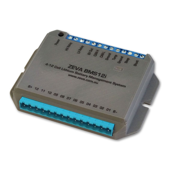
ZEVA BMS12i
www.zeva.com.au
B+ 11 10 09 08 07 06 05 04 03 02 01 B–
BMS12i
4-12 Cell Lithium Battery Management System
Introduction
The ZEVA BMS12i is an integrated battery management system for lithium battery packs
containing 4-12 cells in series and 5-1200Ah capacity. It is suitable for both electric vehicle
and battery storage applications. The BMS12i includes an internal power supply to allow it to
run directly from the battery pack, internal shunt resistors for automatic pack balancing, dual
solid state relay outputs for switching power contactors to protect charging and discharging
of batteries, built-in current shunt interface for measuring current and calculating battery
state of charge, and a CAN bus port for optional colour touchscreen interface or integration
with third party control systems.
The BMS12i Monitor provides information such as voltage, current, power, battery state of
charge, and all individual cell voltages. It can also be used for configuring the operating
parameters of the BMS12i. It may be installed up to 50m from the BMS (if correct shielded
twisted pair cable is used).
Battery management systems are the last line of defence for your battery pack. In normal
circumstances it should not interfere with the battery pack's operation, only intervening
when something goes wrong and protection is required.
1
A
US TRAL IA
Safety Warning
Although 4-12 cell lithium battery packs do not involve lethal voltages, they frequently
involve dangerous amounts of current and power. Proper precautions and electrical
safety procedures should always be observed. Please read this manual carefully to ensure
correct installation and operation. If you are unsure of anything, please contact us before
proceeding.
We have endeavoured to make a safe and reliable product which performs as described,
however since ZEVA has no control over the integration of its products into a battery system,
we can assume no responsibility for the final safety or functionality of the completed
installation. It is up to the end user to determine the suitability of the products for the purpose
employed, and the end user assumes all risks associated. Products should only be installed
by suitably qualified and experienced persons, should be tested thoroughly after installation
to verify correct operation, and should always be used in a safe and lawful manner.
Specifications
•
Number of cells: 4-12
•
Battery types: LiFePO4, LiCo, LiMn, NMC, etc
•
Accuracy: Within 0.002V per cell
•
Battery capacity: 5-1200Ah
•
Current measurement: Up to 1000A via shunt interface, or 1200A via CAN hall sensor
•
Dimensions: 104x78x18mm, 2x Ø4mm mounting holes 98mm apart
•
Outputs: Dual solid state relays, 60V 1A max, internally fused
•
CAN bus interface (non-isolated), 250kbps 29-bit by default
•
Power consumption: Approx 30mA when running (with both output relays closed and a
monitor connected to the CAN bus), 8mA when sleeping.
Installation
The BMS12i should be mounted securely using screws through the holes on the case flanges.
Install the BMS12i in a location protected from direct sun and water, and close to the cells if
possible to minimise cell wiring lengths (under 1m recommended).
The BMS12i has a pluggable screw terminal block for the cell connections, with the most
negative point of the battery pack connected to terminal B–, and successive positive
terminals connected to 01–12. Wire gauge around AWG20-22 is recommended for sufficient
mechanical strength and suitable current rating. To fit wires, strip about 8mm of insulation off
the end, turn the screw terminal counter-clockwise about 8 turns to lower the clamping bar,
insert the wire into the hole, then turn clockwise until the wire is held firmly. We recommend
wiring up the plug and verifying all voltages before connecting to the BMS. The plug requires
a significant amount of force to fully engage; ensure it is plugged all the way in for reliable
connections.
4-12 CELL LITHIUM BATTERY MANAGEMENT SYSTEM
2
Advertisement

Subscribe to Our Youtube Channel
Related Manuals for Zeva BMS12i


Summary of Contents for Zeva BMS12i
- Page 1 The BMS12i should be mounted securely using screws through the holes on the case flanges. state of charge, and a CAN bus port for optional colour touchscreen interface or integration Install the BMS12i in a location protected from direct sun and water, and close to the cells if with third party control systems.
- Page 2 Current Shunt The BMS12i may be supplied with either a 100A, 200A or 500A shunt. The shunt may be installed at either the negative end, positive end, or even somewhere in the middle of the battery pack. The shunt is connected via two wires to the associated terminals on the BMS12i.
- Page 3 CAN H and CAN L lines. The monitor includes termination resistor built-in. Note that the The BMS12i has a Sleep terminal which may be used to put the device into a lower power CAN bus shares its ground reference with battery negative (it is not an isolated interface).
- Page 4 If you choose Enter Setup, the Monitor can be used to Parame t e r : < > modify settings for the BMS12i. The top row selects the Pack ca p a c i t y Shunt size None, 100,...
- Page 5 Stationary Mode generated and charging will be disabled. The BMS12i has two main modes of operation, either normal (for mobile / EV applications) Set to -41C to disable (will show as “Off”) or Stationary Mode (for off grid / backup battery type applications). In normal mode, if an...
- Page 6 To prevent possible damage, the BMS12i is able to switch off its own power supply if any cells get critically low (under 2.0V). If your BMS has turned off due to a critically low cell, simply attach a charging source to the batteries then press the power button to re-enable the BMS.
Need help?
Do you have a question about the BMS12i and is the answer not in the manual?
Questions and answers