Advertisement
Quick Links
Z
e
e r o
m i s s i o n
V
A
e h i c l e s
u s t r A l i A
http://www.zeva.com.au
Electric Vehicle
Management System
The ultimate multifunctional,
integrated control system for your EV
v2.0
Introduction
Thank you for purchasing ZEVA's Electric Vehicle Management System. The EVMS was
developed to address the need for safer, more reliable and better integrated EV conversions.
It combines many common functions and a range of fault detection, providing warnings of
operating errors and automatically responding to serious faults.
•
Instrumentation including voltage, current, power, battery charge, temperature, and
insulation integrity.
•
Analog gauge outputs to re-use OEM fuel gauge, temp gauge and tachometer.
•
Battery management including cell voltage and temperature monitoring with auto-
matic response to under/over-charged batteries, and automatic pack balancing.
•
Contactor control for management of auxiliary contactors, allowing battery pack
break-up and isolation for safety when vehicle is not in use.
•
Optional 2-stage precharger with fault detection for soft-starting motor controllers
•
Detection of over 15 different operating errors/warnings.
A complete EVMS consists of a Core, usually installed in the vehicle's engine bay,
communicating over industry-standard CAN bus with a Monitor module in the vehicle
cabin, and battery management modules located within your battery boxes.
This manual describes the installation and operation of both the EVMS Core and EVMS
Monitor devices. Please refer to documentation supplied with your BMS modules for
information relating to those devices.
Safety Warning
Electric vehicles are high powered machines which involve potentially lethal voltages and
currents. Proper precautions and electrical safety procedures should always be observed,
voltages above 110VDC should be considered dangerous, and vehicles should never be
worked on while power contactor(s) are engaged. Please read this manual carefully to
ensure correct installation and operation. If you are unsure of anything, please contact us
before proceeding.
We have endeavoured to make a safe and reliable product which performs as described,
however since ZEVA has no control over the integration of its products into a vehicle, we can
assume no responsibility for the final safety or functionality of the completed vehicle.
It is up to the end user to determine the suitability of the products for the purpose employed,
and the end user assumes all risks associated. Products should only be installed by suitably
qualified and experienced persons, and should always be used in a safe and lawful
manner.
Advertisement

Related Manuals for Zeva EVMS V2


Summary of Contents for Zeva EVMS V2
- Page 1 If you are unsure of anything, please contact us before proceeding. Electric Vehicle We have endeavoured to make a safe and reliable product which performs as described, however since ZEVA has no control over the integration of its products into a vehicle, we can Management System assume no responsibility for the final safety or functionality of the completed vehicle. v2.0 It is up to the end user to determine the suitability of the products for the purpose employed, and the end user assumes all risks associated.
- Page 2 Specifications Input Connect to the most negative potential of your battery (or • Power supply: 12V nominal (9-18V maximum) negative terminal of motor controller) • Traction pack voltage range: 12-320VDC nominal (±1% accuracy) Main Ctr Coil+ Output To the positive wire of your main contactor coil. The •...
- Page 3 Wiring Diagram The diagram below shows typical wiring for a complete EVMS installation. It may look a little intimidating at first but should become clear as you start to wire up your own EV. Note that the diagram does not show an inertia switch (crash sensor), which should be installed between the 12V battery and the EVMS Core’s 12V supply. You will also usually need to use the key signal to switch a relay for powering auxiliary devices such as brake vacuum pump, power steering pump, water cooling pump, cabin heater, etc.
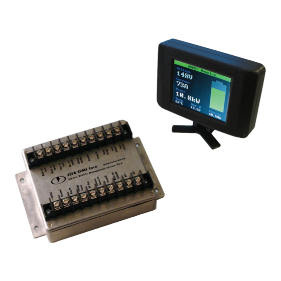
- Page 4 CAN buses work best when wired as a single daisy chain of devices, with 120ohm termination The standard display when Precharging, Running or V olta ge 148V resistors at each end to prevent signal reflection. Most ZEVA CAN-enabled devices have dual Charging, showing instantaneous voltage, current, CAN ports for easy daisy-chaining. The order of devices is unimportant - usually the shortest C urre nt power, temperature, auxiliary battery voltage and path between devices is best.
- Page 5 List of settings - EVMS Core The following table describes the parameters available in the General Settings page. If the EVMS Core detects an error, this warning page Name Range Description Warnin g: will be displayed. In most cases, the error can be Pack capacity 10-1000Ah The rated capacity of your traction battery pack,...
- Page 6 Fuel gauge full 0-100% Because every vehicle’s OEM gauges have Use Fahrenheit YES/NO Changes display of temperature units to different scaling, these four parameters allow Fahrenheit instead of Celcius. Fuel gauge empty 0-100% the EVMS Core to tune it’s outputs to suit your Temp gauge hot 0-100% Error Detection...
- Page 7 State of Charge drift and synchronisation Insulation fault A chassis leakage above the programmed threshold has been The EVMS uses a hall effect sensor for current measurement and, by integrating current over detected. (May indicate an insulation fault, or even water inside time, calculating battery state of charge.
- Page 8 HV terminals. Ideally, you should see over 90% at all times. Tech support and warranty information All ZEVA products are covered by a 12 month warranty against manufacturing faults or failures under normal operating conditions. The warranty does not cover misuse of the...
Need help?
Do you have a question about the EVMS V2 and is the answer not in the manual?
Questions and answers