Table of Contents
Advertisement
Quick Links
Advertisement
Table of Contents

Subscribe to Our Youtube Channel
Related Manuals for SOtM sMB-Q370

Summary of Contents for SOtM sMB-Q370
- Page 1 Motherboard Product Guide www.sotm-audio.com Rev 1.1c...
-
Page 3: Expansion Slot
Motherboard Spec sMB-Q370 Micro-ATX Form Factor Intel® Coffee Lake Processor with Q370 Chipset MECHANICAL FORM FACTOR Micro-ATX: 9.6” x 9.6” (244 mm x 244 mm) SYSTEM Support for 9th and 8th Generation Intel® Core processors, PROCESSOR Intel® Pentium® processors, and Intel® Celeron® processors... - Page 4 REAR I/O 4 x USB 3.1 Gen. 2 (up to 10 Gbps), 2 x USB 2.0 DISPLAY I/O 1 x DisplayPort, 1 x HDMI LAN I/O 1 x RJ-45 AUDIO I/O — INTERNAL CONNECTORS STORAGE 6 x SATA 6Gb/s 4 x USB 2.0, 2 x USB 3.1 Gen.2 LVDS connector (colay eDP connector), Panel power Header (default 5V, option to 12V, 3.3V), DISPLAY I/O...
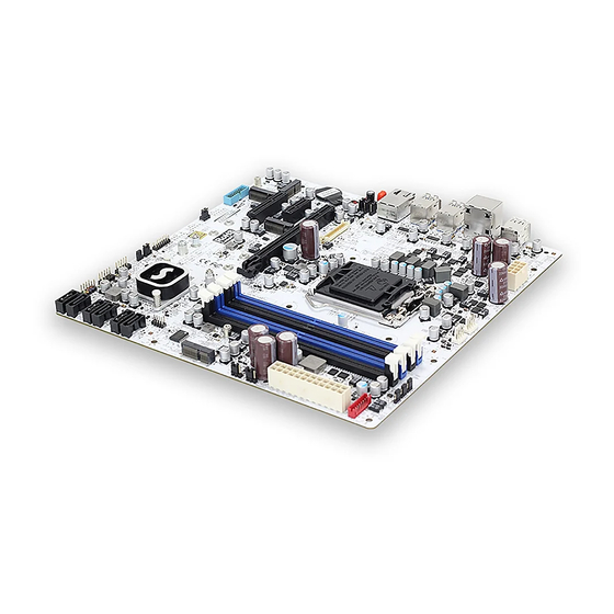
- Page 5 Figure 1 shows the approximate location of the major components on the top side of SOtM sMB-Q370. DP + HDMI USB2.0X2 USB3.0X4 Motherboard layout Figure 1 :...
- Page 6 TABLE 2. SOtM sMB-Q370 COMPONENTS (SHOWN IN FIGURE 1)
- Page 7 The board supports 9 & 8 generation Intel Core processors. Other processors may be supported in the future. This board supports processors with a maximum wattage of 95W (8 core 35W & 6 core 95W) Thermal Design Power (TDP). NOTE This board has specific requirements for providing power to the processor.
- Page 8 Figure : Front Panel Connector(J_FIO_1) NAME Description NAME Description [Out] Front panel HDD_POWER_LED POWER_LED_MAIN Pull-up resistor (Orange color) (330Ω) to +5V (Green color) LED (Green) [Out] Front panel HDD_LED# POWER_LED_ALT [Out] Hard disk (Orange color) activity LED (Green color) LED (Yellow) GROUND POWER_SWITCH# Power button...
- Page 9 PCH_USB31RX_5P PCH_USB31RX_6N PCH_USB31RX_6P PCH_USB31TX_5N PCH_USB31TX_5P PCH_USB31TX_6N PCH_USB31TX_6P USB_PCH_DN6 USB_PCH_DP6 USB_PCH_DN2 USB_PCH_DP2 Table : 20-pin USB3.0 header pin-out reference Figure : LVDS Connector(J5, Ivory color) NAME NAME VCC3 BKLT_PWR VCC3 BKLT_PWR LVDS_DDC_SCL LVDS_DDC_SDA LVDS_HPDET LVDS0_LINK1_CON_DP LVDS0_LINK0_CON_DP LVDS0_LINK1_CON_DN LVDS0_LINK0_CON_DN LVDS0_LINK3_CON_DP LVDS0_LINK2_CON_DP LVDS0_LINK3_CON_DN LVDS0_LINK2_CON_DN LVDS1_LINK1_CON_DP LVDS1_LINK0_CON_DP...
- Page 10 LVDS1_CLK_CON_DP LVDS0_CLK_CON_DP LVDS1_CLK_CON_DN LVDS0_CLK_CON_DN BKLT_PWR BKLT_PWR Table : 40-pin LVDS data header pin-out reference Figure: LPC header pin-out(LPC_HDR1, Black color) NAME NAME LPC_LAD0 VCC3 LPC_LAD1 PLTRST_BUFFER_N LPC_LAD2 L_FRAME_N LPC_LAD3 PORT80_CLK Table : LPC header pin-out Figure : LVDS inverter power header pin-out(JBKL1, Red color) NAME Description LVDS_BKTEN_R...
- Page 11 Ground Ground BRIGHT_UP- BRIGHTNESS UP BRIGHT_DOWN- BRIGHTNESS DOWN Table : 8-pin LVDS inverter power header signals Figure : Dual USB2.0 pin-out(FP_USB2_1, FP_USB2_2, Black color) NAME NAME 5V_USB 5V_USB Data (negative) Data (negative) Data (positive) Data (positive) Ground Ground Key (no pin) No Connect Table : Dual USB 2.0 Header Figure : ATX 24pin pin-out(ATX24P_1, Ivory color)
- Page 12 PS-ON PW-OK 5VSB 3.3V Table : ATX 24pin signals Figure: ATX 8pin pin-out(ATX8P_1, Ivory color) NAME NAME Table: ATX 8pin signals Figure : AT/ATX Header(JPSON1, Black color) NAME PSON_AT_N SW_PWRBT_N Jumper (1-2) : AT mode Jumper (2-3) : NON-AT mode Table: AT/ATX Header...
- Page 13 Figure : BKL PWM Header pin-out(BKLPWM1, Black color) NAME PCH_BACKLIGHT_PWM BKLT_PWM AD5258BRMZ10_PWM Jumper (1-2) : BACKLIGHT PWM is from PCH (Default) Jumper (2-3) : BACKLIGHT PWM is from AD5258BRMZ10 Table : BKL PWM Header Figure : BKL on/off Header(BL_ON_OFF1, Black color) NAME BKLT_EN Jumper (1-2) : On for BKL (Default)
- Page 14 Figure: BKL Voltage Header(BKLVOL1, Black color) NAME VCC3 Jumper (1-2) : VCC (Default) Jumper (3-3) : VCC3 Table : BKL Voltage Header Figure : TPM Header(J46, Black color) NAME NAME 3.3V L_FRAME_N LPC_LAD0 LPC_LAD1 TPM_PLTRST_N LPC_LAD2 LPC_LAD3 TPMPCLK TPM_SERIRQ TPM_MOD_N 3.3V RST_ESPI_RESET_N Table : TPM Header...
- Page 15 Note : If you use an external clock like sCLK-EX, it will take around 10 mins to clear CMOS. So you have to wait more than 10 mins with AC power off. And sMB-Q370 will reboot a few times automatically after CMOS clears or CMOS values changes.
- Page 16 Figure : M.2 M key slot For Storage pin-out(M2M_1, M2M_2, Black color) NAME NAME 3.3Vaux 3.3Vaux 3.3Vaux SUSCLK(32kHz)(O)(0/3.3V) PEDET(OC-PCIe/GND-SATA) Connector Key Connector Key Connector Key Connector Key Connector Key Connector Key Connector Key Connector Key PEWake#(IO)(0/3.3V) REFCLKP PERST#(O)(0/3.3V) or N/C REFCLKN PERST#(O)(0/3.3V) or N/C PETp0/SATA-A+...
- Page 17 3.3Vaux 3.3Vaux 3.3Vaux 3.3Vaux DAS/DSS#(I){OD} 3.3Vaux 3.3Vaux Table : M.2 M key slot For Storage signals Figure : M.2 E key slot For wireless pin-out(M2E_1, M2E_2, Black color) NAME NAME 3.3V 3.3V RESERVED/REFCLKn1 UIM_POWER_SRC/GPIO1/PEWAKE1 RESERVED/REFCLKp1 UIM_POWER_SNK/CLKREQ1# UIM_SWP/PERST1# RESERVED/PETn1 RESERVED RESERVED/PETp1 ALERT# (O)(0/3.3V) I2C_CLK (I)(0/3.3V) RESERVED/PERn1...
- Page 18 COEX2(I/O)(0/1.8V) REFCLKp0 COEX3(I/O)(0/1.8V) VENDOR DEFINED PETn0 VENDOR DEFINED PETp0 VENDOR DEFINED UART CTS (I)(0/1.8V) PERn0 UART RTS (O)(0/1.8V) PERp0 UART RXD (I)(0/1.8V) Connector Key Connector Key Connector Key Connector Key Connector Key Connector Key Connector Key Connector Key UART TXD (O)(0/1.8V) SDIO RESET# (I)(0/1.8V) UART WAKE# (O)(0/3.3V) SDIO WAKE# (O)(0/1.8V)
- Page 19 Figure : SATA Header pin-out(SATA1, SATA2, SATA3, SATA4, SATA5, SATA6, Black color) NAME SATA_TX2_C_DP SATA_TX2_C_DN SATA_RX2_C_DN SATA_RX2_C_DP Table : SATA Header signals Figure : Panel power Header pin-out(J20, Black color) NAME Description No pin 3.3V 3.3V option (default) 12V option LCD_VCC Send voltage to connector No pin...
- Page 20 Figure : LAN LED On/Off Header(J53, J54, J55, Black color) LINK_ACTIVITY LAN1_SPEED_100_R LAN1_SPEED_1000_R LAN1_LINK_ACTIVITY_L LAN1_SPEED_100 LAN1_SPEED_1000 Jumper (1-2) : LED on Jumper (2-3) : LED off Table : LAN LED On/Off Figure : Boot Delay Time Selection Header(PLTRST_DLY, Black color) NAME VR_READY Delay capacitor...
-
Page 21: Bios Specification
Motherboard BIOS Specification... - Page 22 MAIN PAGE Field Name BIOS Vender Default Value AMI Megatrends Comment This field is not selectable. There is no help text associated with it. Field Name Core Version Default Value 5.13 Comment This field is not selectable. There is no help text associated with it. Field Name Compliancy Default Value...
- Page 23 Field Name BIOS Version Default Value Display the version of the BIOS Comment This field is not selectable. There is no help text associated with it. Field Name Build Date Default Value Display build time of the BIOS Comment This field is not selectable. There is no help text associated with it. Field Name ME FW Version Value...
- Page 24 Field Name System Time Default Value [hh :mm :ss] Possible Value hh : 0-23 mm : 0-59 ss : 0-59 Help Set the Time. Use Tab to switch between Time elements.
-
Page 25: Advanced Page
ADVANCED PAGE Field Name CPU Configuration Help CPU Configuration Parameters. Comment Press Enter when selected to go into the associated Sub-Menu. Field Name PCH-FW Configuration Help Configure Management Engine Technology Parameters. Comment Press Enter when selected to go into the associated Sub-Menu. Field Name Trusted Computing Help... - Page 26 Field Name NCT7802Y HW Monitor Help Monitor hardware status Comment Press Enter when selected to go into the associated Sub-Menu. Field Name S5 RTC Wake Settings Help Enable system to wake from S5 using RTC alarm Comment Press Enter when selected to go into the associated Sub-Menu. Field Name Intel TXT Information Help...
-
Page 27: Cpu Configuration
2.1 CPU CONFIGURATION Field Name Type Default Value [Intel CPU Brand String] Comment This field is not selectable. There is no help text associated with it. Field Name Default Value Displays CPU Signature Comment This field is not selectable. There is no help text associated with it. Field Name Speed Default Value... - Page 28 Field Name L2 Cache Default Value L2 Cache Size Comment This field is not selectable. There is no help text associated with it. Field Name L3 Cache Default Value L3 Cache Size Comment This field is not selectable. There is no help text associated with it. Field Name L4 Cache Default Value...
-
Page 29: Pch-Fw Configuration
Field Name Intel Trusted Execution Technology Default Value [Disabled] Possible Value Enabled Disabled Help Enables utilization of additional hardware capabilities provided by Intel (R) Trusted Execution Technology. Changes require a full power cycle to take effect. 2.2 PCH-FW CONFIGURATION Field Name ME Firmware Version Default Value ME version value by BIOS release... - Page 30 Field Name ME Firmware Status 1 Default Value 0x90000255 Comment This field is not selectable. There is no help text associated with it. Field Name ME Firmware Status 2 Default Value 0x80108106 Comment This field is not selectable. There is no help text associated with it. Field Name Manageability Features State Default Value...
-
Page 31: Amt Configuration
2.2.1 AMT CONFIGURATION Field Name ASF support Default Value [Enabled] Possible Value Enabled Disabled Help Enable/Disable Alert Standard Format support. Field Name USB Provisioning of AMT Default Value [Disabled] Possible Value Enabled Disabled Help Enable/Disable of AMT USB Provisioning. -
Page 32: Trusted Computing
2.3 TRUSTED COMPUTING Field Name Security Device Support Default Value [Enable] Possible Value Enable Disable Help Enables or Disables BIOS support for security device. O.S. will not show Security Device. TCG EFI protocol and INT1A interface will not be available. Field Name Pending operation Default Value... -
Page 33: Acpi Settings
Field Name TPM2.0 UEFI Spec Version Default Value [TCG_2] Possible Value TCG_1_2 TCG_2 Help Select the TCG2 Spec Version Support, TCG_1_2: The Compatible mode for Win8/Win10, TCG_2: Support new TCG2 protocol and event format for Win10 or later. 2.4 ACPI SETTINGS Field Name Enable ACPI Auto Configuration Default Value... -
Page 34: Smart Settings
Field Name ACPI Sleep State Default Value [S3 (Suspend to RAM)] Possible Value Suspend Disabled S3 (Suspend to RAM) Help Select the highest ACPI sleep state the system will enter when the SUSPEND button is pressed. 2.5 SMART SETTINGS Field Name SMART Self Test Default Value [Disabled]... - Page 35 2.6 NCT7802Y HW MONITOR Type Range CPU Temperature -20 ~ (By Processor Tjmax) °C VR Temperature -20 ~ 120 °C System Temperature -20 ~ 120 °C CPU Fan Speed There are many kinds of the fan could be installed into the system, so we could only set 0 RPM for the failed fan speed, and there is also no System Fan Speed high RPM limitation.
-
Page 36: S5 Rtc Wake Setting
2.7 S5 RTC WAKE SETTING Note: RTC wake up will not work when “DeepSx Power Policies set to enable” Field Name Wake system from S5 Default Value [Disabled] Possible Value Disabled Fixed Time Dynamic Time Help Enable or disable System wake on alarm event, Select FixedTime, system will wake on the hr::min::sec specified. -
Page 37: Intel Txt Information
Field Name Wake up second(Show when Wake system from S5 set to Fixed Time) Default Value Possible Value 0 - 59 Select 0 – 59 for Second Help Field Name Wakeup minute increase Default Value Possible Value 0 - 5 Help 2.8 INTEL TXT INFORMATION... -
Page 38: Ami Graphic Output Protocol Policy
AMI GRAPHIC OUTPUT PROTOCOL POLICY (AVAILABLE WHEN UEFI VIDEO) Field Name Output Select Default Value By attached device. Possible Value EDP1(LVDS Control enabled) / DP1 / HDMI3 Help Output Interface Field Name LCD Panel Type Default Value [1920x1080 24bit Dual Channel] Possible Value 800x600 18bit Single Channel... -
Page 39: Usb Configuration
1680x1050 24bit Dual Channel 1600x1200 24bit Dual Channel 1920x1080 24bit Dual Channel 1920x1200 24bit Dual Channel Help Select LCD panel used by Internal Graphics Device by selecting the appropriate setup item. Field Name Backlight Control Default Value [PWM Normal] Possible Value PWM Inverted PWM Normal Help... - Page 40 Field Name XHCI Hand-off Default Value [Enabled] Possible Value Disabled Enabled Help This is a workaround for OSes without XHCI hand-off support. The XHCI ownership change should be claimed by XHCI driver. Field Name USB Mass Storage Driver Support Default Value [Enabled] Possible Value Disabled...
-
Page 41: Network Stack Configuration
2.11 NETWORK STACK CONFIGURATION Field Name Network stack Default Value [Disabled] Possible Value Disabled Enabled Help Enable/Disable UEFI Network stack. Field Name Ipv4 PXE Support (Available when Network stack Enabled) Default Value [Enabled] Possible Value Disabled Enabled Help Enable/Disable Ipv4 PXE Boot Support. If disabled IPV4 PXE boot support will not be available. -
Page 42: Csm Configuration
2.12 CSM CONFIGURATION Field Name CSM Support Default Value [Disabled] Possible Value Disabled Enabled Help Enable/Disable CSM Support. Field Name Network (Available when CSM Support Enabled) Default Value [Do not launch] Possible Value Do not launch UEFI Legacy Help Controls the execution of UEFI and Legacy Network OpROM Field Name Storage (Available when CSM Support Enabled) Default Value... -
Page 43: Nvme Configuration
Field Name Video (Available when CSM Support Enabled) Default Value [UEFI] Possible Value Do not launch UEFI Legacy Help Controls the execution of UEFI and Legacy Video OpROM Field Name Other PCI devices (Available when CSM Support Enabled) Default Value [UEFI] Possible Value Do not launch... -
Page 44: Chipset Page
CHIPSET PAGE Field Name System Agent (SA) Configuration Help System Agent (SA) Parameters Comment Press Enter when selected to go into the associated Sub-Menu. Field Name PCH-IO Configuration Help PCH Parameters Comment Press Enter when selected to go into the associated Sub-Menu. -
Page 45: System Agent (Sa) Configuration
3.1 SYSTEM AGENT (SA) CONFIGURATION Field Name Memory Configuration Help Memory Configuration Parameters Comment Press Enter when selected to go into the associated Sub-Menu. Field Name Graphics Configuration Help Graphics Configuration Comment Press Enter when selected to go into the associated Sub-Menu. Field Name PEG Port Configuration Help... -
Page 46: Memory Configuration
3.1.1 MEMORY CONFIGURATION Field Name Memory RC Version Help Memory Reference Code version Comment This field is not selectable. There is no help text associated with it. Field Name Memory Frequency Help Memory speed Comment This field is not selectable. There is no help text associated with it. Field Name Memory Timings (tCL-tRCD-tRP-tRAS) Help... -
Page 47: Graphics Configuration
3.1.2 GRAPHICS CONFIGURATION Field Name Primary Display Default Value [Auto] Possible Value Auto / IGFX / PEG Help Select which of IGFX/PEG/PCI Graphics device should be Primary Display Or select SG for Switchable Gfx. Field Name Internal Graphics Default Value [Auto] Possible Value Auto / Disabled / Enabled... -
Page 48: Lcd Control
Field Name DVMT Total Gfx Mem Default Value [256M] Possible Value 128MB / 256MB / MAX Help Select DVMT5.0 Total Graphic Memory size used by the Internal Graphics Device. 3.1.2.1 LCD CONTROL Field Name Primary IGFX Boot Display Default Value [VBIOS Default] Possible Value VBIOS Default / LVDS(LVDS Control enabled) / DP1 / HDMI... - Page 49 Field Name LCD Panel Type Default Value [1920x1080 24bit Dual Channel] Possible Value 800x600 18bit Single Channel 1024x768 18bit Single Channel 1024x768 24bit Single Channel 1280x768 18bit Single Channel 1280x800 24bit Single Channel 1280x960 18bit Single Channel 1280x1024 24bit Dual Channel 1366x768 18bit Single Channel 1366x768 24bit Single Channel 1440x900 24bit Dual Channel...
-
Page 50: Peg Port Configuration
3.1.3 PEG PORT CONFIGURATION Field Name PEG 0:1:0 Default Value By detect. Possible Value Not Present / Gen1 / Gen2 / Gen3 Comment This field is not selectable. There is no help text associated with it. Field Name Max Link Speed Default Value [Auto] Possible Value... -
Page 51: Pch-Io Configuration
3.2 PCH-IO CONFIGURATION Field Name PCIE Express Configuration Help PCIE Express Configuration settings Comment Press Enter when selected to go into the associated Sub-Menu. Field Name SATA And RST Configuration Help SATA Device Options Settings Comment Press Enter when selected to go into the associated Sub-Menu. Field Name USB Configuration Help... - Page 52 Field Name LAN Controller Default Value [Enabled] Possible Value Enabled Disabled Help Enable/Disable onboard RTL8111HS Field Name Wake On Lan Default Value [Enabled] Possible Value Enabled Disabled Help Enable/Disable integrated LAN to wake the system. Field Name DeepSx Power Policies Default Value [Disabled] Possible Value...
-
Page 53: Pci Express Configuration
3.2.1 PCI EXPRESS CONFIGURATION Field Name PCI Express X4 Slot Help PCI Express Root Port Settings Comment Press Enter when selected to go into the associated Sub-Menu. Field Name PCI Express M.2 M M2M_1 Help PCI Express Root Port Settings Comment Press Enter when selected to go into the associated Sub-Menu. -
Page 54: Pci Express X4 Slot
Field Name PCI Express M.2 M M2M_2 Help PCI Express Root Port Settings Comment Press Enter when selected to go into the associated Sub-Menu. 3.2.1.1 PCI EXPRESS X4 SLOT Field Name ASPM Default Value [Auto] Possible Value Disabled / L0s / L1 / L0sL1 / Auto Help Set the ASPM Level:Force L0s - Force all links to L0s State AUTO - BIOS auto configure DISABLE - Disables ASPM... - Page 55 Field Name PCIe Speed Default Value [Auto] Possible Value Auto / Gen1 / Gen2 / Gen3 Help Configure PCIe Speed 3.2.1.2 PCI EXPRESS M.2 M M2M_1 Field Name ASPM Default Value [Auto] Possible Value Disabled / L0s / L1 / L0sL1 / Auto Help Set the ASPM Level:Force L0s - Force all links to L0s State AUTO - BIOS auto configure DISABLE - Disables ASPM...
- Page 56 Field Name PCIe Speed Default Value [Auto] Possible Value Auto / Gen1 / Gen2 / Gen3 Help Configure PCIe Speed 3.2.1.3 PCI EXPRESS M.2 E M2E_1 Field Name ASPM Default Value [Auto] Possible Value Disabled / L0s / L1 / L0sL1 / Auto Help Set the ASPM Level:Force L0s - Force all links to L0s State AUTO - BIOS auto configure DISABLE - Disables ASPM...
-
Page 57: Pci Express X1 Slot
Field Name PCIe Speed Default Value [Auto] Possible Value Auto / Gen1 / Gen2 / Gen3 Help Configure PCIe Speed 3.2.1.4 PCI EXPRESS X1 Slot Field Name ASPM Default Value [Auto] Possible Value Disabled / L0s / L1 / L0sL1 / Auto Help Set the ASPM Level:Force L0s - Force all links to L0s State AUTO - BIOS auto configure DISABLE - Disables ASPM... - Page 58 3.2.1.5 PCI EXPRESS M.2 E M2E2 Field Name ASPM Default Value [Auto] Possible Value Disabled / L0s / L1 / L0sL1 / Auto Help Set the ASPM Level:Force L0s - Force all links to L0s State AUTO - BIOS auto configure DISABLE - Disables ASPM Field Name L1 Substates Default Value...
- Page 59 3.2.1.6 PCI EXPRESS M.2 M M2M_2 Field Name ASPM Default Value [Auto] Possible Value Disabled / L0s / L1 / L0sL1 / Auto Help Set the ASPM Level:Force L0s - Force all links to L0s State AUTO - BIOS auto configure DISABLE - Disables ASPM Field Name L1 Substates Default Value...
-
Page 60: Sata And Rst Configuration
3.2.2 SATA AND RST CONFIGURATION Field Name SATA Mode Selection Value [AHCI] Possible Value AHCI / Intel RST Premium With Intel Optane System Acceleration Help Determines how SATA controller(s) operate. Field Name SATA1 Value Display the installed SATA port device. Comment This field is not selectable. - Page 61 Field Name SATA4 Value Display the installed SATA port device. Comment This field is not selectable. There is no help text associated with it. Field Name SATA5 Value Display the installed SATA port device. Comment This field is not selectable. There is no help text associated with it. Field Name SATA6 Value...
- Page 62 Field Name xDCI Support Value [Disabled] Possible Value Disabled / Enabled Help Enable/Disable xDCI (USB OTG Device). Field Name Rear IO LAN USB3 Gen2 Power Value [Enabled] Possible Value Disabled / Enabled Help Enable/Disable Type C port. Field Name Rear IO USB3 Gen2 Power Value [Enabled] Possible Value...
-
Page 63: Hd Audio Configuration
3.2.4 HD AUDIO CONFIGURATION Field Name HD Audio Value [Disabled] Possible Value Enabled / Disabled Help Control Detection of HD-Audio device. Disabled = HDA will be unconditionally disabled Enabled = HDA will be unconditionally enabled... - Page 64 SECURITY Field Name Administrator Password Help Set Administrator Password Field Name User Password Help Set User Password. Field Name HDD Security drive Help HDD Security Configuration for selected drive Comment Press Enter when selected to go into the associated Sub-Menu. Field Name ME Update Value...
-
Page 65: Hdd Security
Field Name Secure Flash Update Help Secure Flash Update support Comment Press Enter when selected to go into the associated Sub-Menu. 4.1 HDD SECURITY Field Name Set User Password Help Set HDD User Password. *** Advisable to Power Cycle System after Setting Hard Disk Passwords ***.Discard or Save changes option in setup does not have any impact on HDD when password is set or removed. -
Page 66: Secure Boot
4.2 SECURE BOOT Note: This page will not be affected by load default. Field Name Secure Boot Default Value [Disabled] Possible Value Enabled Disabled Help Secure Boot feature is Active if Secure Boot is Enabled,Platform Key(PK) is enrolled and the System is in User mode.The mode change requires platform reset Field Name Secure Boot Mode Default Value... -
Page 67: Key Management
Field Name Reset to Setup Mode Help Delete all Secure Boot key databases from NVRAM Field Name Key Management Help Enables expert users to modify Secure Boot Policy variables without full authentication Comment Enables expert users to modify Secure Boot Policy variables without full authentication 4.2.1 KEY MANAGEMENT Note: This page will not be affected by load default. - Page 68 Field Name Reset to Setup Mode Help Delete all Secure Boot key databases from NVRAM Field Name Export Secure Boot variables Help Copy NVRAM content of Secure Boot variables to files in a root folder on a file system device Field Name Enroll Efi Image Help...
- Page 69 Field Name Authorized Signatures Default Value Size:0, Keys:0, Key source: No Keys Help Enroll Factory Defaults or load certificates from a file: 1.Public Key Certificate: a)EFI_SIGNATURE_LIST b)EFI_CERT_X509 (DER) c)EFI_CERT_RSA2048 (bin) d)EFI_CERT_SHAXXX 2.Authenticated UEFI Variable 3.EFI PE/COFF Image(SHA256) Key Source: Factory,External,Mixed Comment Press Enter when selected to go into the associated Sub-Menu.
-
Page 70: Secure Flash Update
3.EFI PE/COFF Image(SHA256) Key Source: Factory,External,Mixed Comment Press Enter when selected to go into the associated Sub-Menu. 4.3 SECURE FLASH UPDATE Field Name Path for ROM Image Help Enter the path to the BIOS update option Notice : ROM Image must in the root folder of storage device. File name must match with current BIOS project. - Page 71 BOOT Field Name Setup Prompt Timeout Default Value Possible Value 1~65535 Help Number of seconds to wait for setup activation key. 65535(0xFFFF) means indefinite waiting. Field Name Bootup NumLock State Default Value [On] Possible Value Help Select the keyboard NumLock state Field Name Boot mode select Default Value...
- Page 72 Field Name Boot Option #1 Default Value [USB Floppy] Possible Value USB Floppy, CD/DVD, USB CD/DVD, Hard Disk , USB Key, USB Hard Disk , Network, Disabled, (UEFI Only)UEFI AP:UEFI: Build- in EFI Shell Help Sets the system boot order Field Name Boot Option #2 Default Value...
- Page 73 Field Name Boot Option #8 (UEFI Only) Default Value [UEFI AP:EFI:Built-in EFI Shell] Possible Value USB Floppy, CD/DVD, USB CD/DVD, Hard Disk , USB Key, USB Hard Disk , Network, Disabled, (UEFI Only)UEFI AP:UEFI: Build- in EFI Shell Help Sets the system boot order Field Name (UEFI) USB Floppy Drive BBS Priorities Help...
- Page 74 5.1 (LIST BOOT DEVICE TYPE) DRIVE BBS PRIORITIES Field Name Boot Option #1 Default Value Possible Value Boot Device Name 1 of this type, Disable Help Sets the system boot order Field Name Boot Option #2 Default Value Possible Value Boot Device Name 2 of this type, Disable Help Sets the system boot order...
-
Page 75: Save And Exit
Discard Changes and Rest Help Reset system setup without saving any changes. Field Name Restore Defaults Help Restore/Load Default values for all the setup options. Note : sMB-Q370 will reboot a few times automatically after CMOS clears or CMOS values changes. - Page 76 RECOVERY PAGE (ACTIVE FOR 4.3 SECURE FLASH UPDATE ONLY) Field Name Reset NVRAM Default Value [Disabled] Possible Value Enabled Disabled Help Set this option to reset NVRAM to default values Field Name Process with flash update Help Select this to start flash update...
-
Page 77: Regional Notice For California
KC: Korea Warning Statement 가정용 방송통신기자재 이 기기는 가정용(B 급)으로 전자파적합기기로서 주로 가정에서 사용하는 것을 목적으로 하며, 모든 지역에서 사용할 수 있습니다. 인증정보 적합성평가를 받은자의 상호 : SOtM 기자재의 명칭(모델명) : Mother Board 인증번호 : R-R-SoM-sMB-Q370 제조자/제조국가 : SOtM/대한민국 Regional notice for California WARNING! This product may contain chemicals known to the State of California to cause cancer, birth defects or other reproductive harm. - Page 80 www.sotm-audio.com...
Need help?
Do you have a question about the sMB-Q370 and is the answer not in the manual?
Questions and answers