Table of Contents
Advertisement
Quick Links
Advertisement
Table of Contents

Related Manuals for Link CAN Gauge

Summary of Contents for Link CAN Gauge
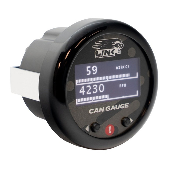
- Page 1 CAN GAuGe USER MANUAL Part No. 101-0226...
- Page 2 Link CAN Bus Connection ..... . 3 Terminating Resistor Configuration ... 3-4 •...
- Page 3 Leave the terminating resistor jumper in The Link CAN Gauge includes a CAN connection cable that is place if the CAN Gauge is the last device in the chain of CAN devices. pre-terminated to a DTM-4 connector. There is also a mating Remove the jumper if there are already two terminating resistors at the DTM-4 connector kit included in the box.
- Page 4 • If you have two Link CAN Gauges, they can be programmed separately. • Turn on your ignition to turn on Link CAN Gauge. The welcome screen will be shown. • Connect to the gauge via Wi-Fi by tapping on settings > Wi-Fi.
- Page 5 sAve & seNd CoNfIGurAtIoN: pClINk CAN streAm CoNfIGurAtIoN: • Tap the icon in the top right and tap Save. • Enter a name under “Enter Save File Name” and tap Save. • Open PCLink • To program, tap Send Configuration. The gauge will be programmed •...
- Page 6 PCLink Extended CAN Channels 2 for exteNded ChANNels: • Select another spare CAN channel. • Set Mode to “Transmit User Stream X” (Where X is the next unused transmit or receive user stream number). • Set CAN ID to 50. •...
- Page 7 A rANGe of ACCessorIes to help You truelY uNleAsh poteNtIAl of Your eNGINe! Part No. 101-0226...
Need help?
Do you have a question about the CAN Gauge and is the answer not in the manual?
Questions and answers