
Related Manuals for Link PJ7rmn5068a

Summary of Contents for Link PJ7rmn5068a
- Page 1 PJ7 Headset Interface Configuration and Installation Manual Link Communications, Inc. 1035 Cerise Road Billings, MT 59101 (406) 245-5002 www.link-comm.com...
- Page 2 The settings are volatile therefore they will need to be set-up by your software each time. When ordering additional PJ7's Link will happily set-up defaults for your PJ7's. When power is then applied, your settings will be recalled requiring no customization from your software.
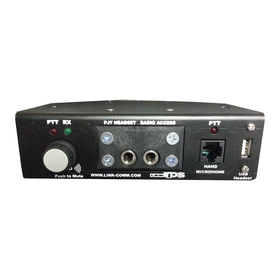
- Page 3 Front Configuration: PJ7: When using the PJ7 you need to use a 6-wire headset that supports PTT on the wiring harness. If you prefer to use a foot pedal the connections are located on the back. Plugging in the headset causes a keyboard event as well as unplugging it causes a different event.
- Page 4 “potato” microphone. The connector is configured to accept any Motorola(TM) RJ45 connector based accessory mic’s (Motorola # RMN5068A). These microphones are available from Link Communications. It’s PTT function is different from the PTT of the PJ7, and contains its own separate mic level configuration.
- Page 5 Back Configuration: USB Port: This connection is used to connect the PJ7 to the computer running your CAD software. A USB cable is included with the PJ7 module. Power is provided from the computers USB port so external powering is not necessary unless running the 10W powered speaker output. External Speaker Line Level Output: The external line level audio output is designed to feed a self-powered speaker, such as computer speakers.
- Page 6 Contact Link Communications for availability. Audio input is routed from the PJ7 when using the external foot pedal, custom routing can be changed based on need, contact Link Communications for details. External 10W power speaker: The PJ7 provides a powered speaker output that can be either Left or Right channels. When operating the speaker you will need to attach an external +12V power supply with a 2.5mm...
- Page 7 CAD software to make custom changes to the PJ7 based on the logged on operator therefore defaults are overwritten by the CAD software when it starts. If necessary Link can default purchased units to contain the customers preferred settings on power-up, contact Link Communications for details.
- Page 8 This readout indicates the settings of the PJ7. To make a change you will need to enter one of the commands to manipulate the interface. The commands have a specific format and must be followed otherwise the command will not execute. Commands: 0 - Recall the settings of the PJ7 Format: [0]...
- Page 9 Each input has a “Pressed” and a “Released” event that may need to be assigned. Each event can contain a sequence of keystrokes, mouse clicks and joystick actions. If a sequence in not supported then contact Link Communications for assistance. HID programmable events:...
- Page 10 Settings: Mode: Hardware Resident Mode Steps: 1) File, Read Device: This reads the setting already programmed into the module 2) Cycle the input you need to assign, for example turn the volume pot one click and the software will provide you an assignment screen 3) Assign Keystrokes by typing on the keyboard (you will see the...
- Page 11 Technical Support: support@link-comm.com Software Updates: http://link-comm.com/index.php/site/support Click on LinkTDS PJ7 Software Link Communications, Inc. 1035 Cerise Road Billings, MT 59101 (406) 245-5002 www.link-comm.com...
- Page 12 Appendix: Schematic Diagrams...
Need help?
Do you have a question about the PJ7rmn5068a and is the answer not in the manual?
Questions and answers