Table of Contents
Advertisement
Quick Links
X-9900
Revision 03
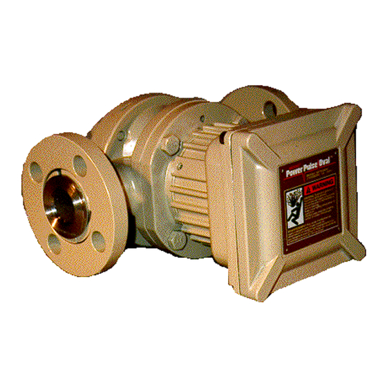
Model 9900 Series Oval Gear Meter
with Smart Meter Manager
Installation and Operation Manual
1
Brodie Meter Co., LLC
19267 Highway 301 North (30461)
Phone: (912) 489-0200
PO Box 450
Fax: (912) 489-0294
Statesboro, GA 30459-0450
www.brodiemeter.com
Manufacturers of BiRotors, Oval Gear Meters, and Control Valves
Advertisement
Table of Contents

Related Manuals for Brodie 9900 Series

Summary of Contents for Brodie 9900 Series
- Page 1 X-9900 Revision 03 Model 9900 Series Oval Gear Meter with Smart Meter Manager Installation and Operation Manual Brodie Meter Co., LLC 19267 Highway 301 North (30461) Phone: (912) 489-0200 PO Box 450 Fax: (912) 489-0294 Statesboro, GA 30459-0450 www.brodiemeter.com Manufacturers of BiRotors, Oval Gear Meters, and Control Valves...
- Page 2 2222222...
- Page 3 1-912-489-0200 and the requested manual will be provided. Save this instruction manual for future reference. • If you do not understand any of the instructions, contact your Brodie representative for clarification. • Follow all warnings, cautions, and instructions marked on and supplied with the product.
- Page 4 Notice Brodie Meter Co., LLC (“Brodie”) shall not be liable for technical or editorial errors in this manual or omissions from this manual. Brodie makes no warranties, expressed or implied, including the implied warranties of merchantability and fitness for a particular purpose with respect to this manual and, in no event, shall Brodie be liable for any special or consequential damages including, but not limited to, loss of production, loss of profits, etc.
- Page 5 Services, or repair or replace F.O.B. point of manufacture that portion of the Goods or firmware found by Brodie to be defective, or refund the purchase price of the defective portion of the Goods/Services. All replacements or repairs necessitated by inadequate maintenance, normal...
-
Page 7: Table Of Contents
Table of Contents 1.0 Oval Flowmeter Series 9900 ..................3 1.1 Description ..............................3 1.2 Design Features - Oval Flowmeter ......................3 1.3 Principle of Operation - Oval Flowmeter ....................3 1.4 Specifications - Oval Flowmeter ......................... 4 1.5 Specifications - Smart Meter Manager ..................... 10 2.0 Installation ........................ - Page 8 This page intentionally left blank. 2222222...
-
Page 9: Oval Flowmeter Series 9900
• 2-wire, loop-powered device for ease of wiring and installation 1.1 Description • 4-20 mA analog output with Bell-202 modulated The Brodie 9900 Series Oval Flowmeter/ HART communication channel Transmitter with Smart Meter Manager (SMM) is • User selectable 0% and 100% analog output... -
Page 10: Specifications - Oval Flowmeter
continuous flow pattern. When in the position as • Shafts shown in Figure 1.1, Diagram 1, all of the driving Standard: 316 stainless steel torque resulting from differential pressure is Optional: Chrome Plated applied to Gear A. Gear B has zero driving •... - Page 11 Table 1.1 Capacities and Operating Range, Mass Hot Water Gasoline Kerosene Light Oil Heavy Oil Line Size Model Units Water 140 to 230°F 0.2 cP 0.3 to 1.7 cP 0.7 to 1.8 2 to 4 cP 5 to 300 cP (Inches) Number (U.S.
- Page 12 Ratings: Output Signals: Maximum Working Temperature (Limited to 4-20 mA Analog Output electronics): Update Rate: 4 times per sec. Range: 3.8 to 22.0 Process Operating Temperature Class A: -40°F to 230°F (-40°C to 110°C) Contact Output Class C: 230°F to 400°F (110°C to 204°C) Open collector: assignable to alarm output, Ambient Operating Temperature reverse flow indicator or manual value...
- Page 13 Figure 1.3 Power Supply/Maximum Load Resistance. Figure 1.4 Pressure Loss and Flow Range for High Viscosity Liquids. Figure 1.5 Relationship between Viscosity and Coefficient of Maximum Flow Rate.
- Page 14 Figure 1.6 9900 Series Dimensions Mounting Dimensions Brodie 9900 Series Oval Flowmeter with UMB. Figure 1.7 typical Application: 9900 Series Oval Flowmeter with Integral Smart Meter Manager 8888888 Brodie Series 9900 Oval Flowmeter with Smart Meter Manager...
- Page 15 Figure 1.8 Typical Application: 9900 Series Oval Flowmeter with Smart Meter Manger. Local Operator interface available with complete Model 20 only.
-
Page 16: Specifications - Smart Meter Manager
1.5 Specifications - Smart Meter Manager Maximum off-state voltage: 30 V dc Maximum on-state voltage: 1.2 Vdc Maximum on-state current: 40 mA Warning Standard Pulse Outputs Do not operate this instrument in excess of the Type: Open collector, two channels (two single- specifications below. -
Page 17: Installation
Fax: 1 912 489 0294 2.2 Recommended Storage Practice 2.4 Installation - Mechanical If intermediate or Iong-term storage is required for equipment, as supplied by Brodie Meter, it is Warning recommended that the equipment be stored in accordance with the following: Do not operate this instrument in excess of the a. -
Page 18: Installation - Electrical
Transmitter electrical installation consists of connecting power, output and accessory wiring to Caution the Smart Meter Manager is in the universal mounting box on top of the oval gear meter. Observe and follow ESD protection procedures when in contact with printed circuit boards or A. - Page 19 bundle the RTD cable with power wiring. A 4-wire Caution RTD is the most accurate because it nulls out the effects of lead-wire resistance from disturbing the Because this unit uses an intrinsically safe process temperature reading. If the 4th wire is not sensor circuit, an earth ground must be supplied available, then a jumper wire must be installed to meet the hazardous area certification.
- Page 20 Figure 2.3 UMB Wiring Diagram Figure 2.4 UMB Entiity Concept 14141414141414...
- Page 21 Figure 2.6 Single Phase, Open Collection Pulse Output Typical Wiring Diagram Figure 2.7 RTD (Resistance Temperature Detector) Wiring Diagram Figure 2.8 Typical Digital Wiring Diagram...
-
Page 22: Operation
3.0 Operation For applications in which an RTD is used, proper values must also be programmed into the RTD 3.1 Pre-Start Check values. The density and RTD variables are accessible with the HART Communicator The SMM is in the meter’s universal mounting box on top of the meter of Flowmeter 3.3 Operation of the HART Communicator with Smart Meter Manager... - Page 23 Table 3.1 Default Values for Variable Configuration...
- Page 24 Figure 3.1 Smart Meter Manager Device Description Tree (Detailed Set-up) 18181818181818...
- Page 25 Figure 3.2 Smart Meter Manager Device Description Tree (Detailed Set-up) * See Detailed Menu Listing, Figure 3.2...
- Page 26 Figure 3.3 Smart Meter Manager LOl Main Menu Figure 3.4 Smart Meter Manager LOl Basic Menu Listing 20202020202020...
- Page 27 c.Manual Programming or Reprogramming of Figure 3.6 the SMM electronics. If electronic parameters Typical HART Communicator Interface were not preprogrammed prior to shipment or new settings are required, programming of the SMM transmitter with or without alarms and pulse output may also be done locally via a Fisher-Rosemount Model 275 hand held Communicator.
- Page 28 If preferred, the meter with transmitter maybe returned for recalibration at the Brodie Meter Service Department for a fee. c. Basic Transmitter Setup Parameters Refer to Figures 3.1 and 3.2. These are meter identification parameters set prior to shipment of the meter.
- Page 29 the defined’destination’ digital contact closure. Pulse Output: Pulse Out Scaler, Pulse Out Width Therefore the alarms may be managed The SMM has a pulse output channel that according to local operating practices and the indicates flow rate as a variable frequency and need to notify upstream control/safety systems.
- Page 30 The following are two examples of typical Note: Two Warnings will Typically appear. programming via a FisherRosemount Model 275 • Warning Pressing OK will change device hand held communicator. output. Put loop in manual. EXAMPLE 1: Programming Flow-Rate Units. • Warning Return control loop to automatic control.
-
Page 31: Maintenance
Basic Meter Inspection Symptom: The fluid will 4.0 Maintenance not pass through the meter Possible Cause: Rotors jammed with scales or other foreign 4.1 General matter causing the rotors not to rotate. The 9900 Oval requires no routine maintenance, cleaning or lubricating. However, establish a schedule for periodic checking and cleaning of A. - Page 32 Caution Caution Never use gripping tools on internal Extreme caution should be taken as the components of the measuring unit, for this can crescent shaped pockets of the measuring damage the unit. chamber may still contain fluid. See WARNING above for reference source for handling e.
-
Page 33: Removal Of Smart Meter Manager
4.3 Removal of Smart Meter Manager Automatic diagnostics can trigger alarms indicating poor communications, memory integrity, Warning or sensor problems. The user can define whether these malfunctions are serious and instruct how The mating surfaces of the UMB housing the 4-20 mA analog signal should be sent to a constitute flame path areas. - Page 34 This page intentionally left blank. 28282828282828...
- Page 36 This page intentionally left blank. 30303030303030...
- Page 38 This page intentionally left blank. 32323232323232...
- Page 40 Phone: (912) 489-0200 implied, regarding the products or services described PO Box 450 Fax: (912) 489-0294 herein or their use or applicability. Brodie Meter Co., LLC reserves the right to modify or improve the designs or Statesboro, GA 30459-0450 www.brodiemeter.com specifications of such products at any time without notice.
Need help?
Do you have a question about the 9900 Series and is the answer not in the manual?
Questions and answers