Table of Contents
Advertisement
Quick Links
Advertisement
Table of Contents

Related Manuals for CSI Wireless SBX-3

Summary of Contents for CSI Wireless SBX-3
- Page 1 SBX-3 Reference Manual Part Number: 875-0031-001 Date: May 2001...
- Page 2 CSI Wireless, INC. 1200 - 58 Avenue S.E. Calgary, Alberta, Canada T2H 2C9 Telephone number: +1-403-259-3311 Fax number: +1-403-259-8866 E-mail address: info@csi-wireless.com Web Site: www.csi-wireless.com SBX-3 Reference Manual...
- Page 3 CSI Wireless, Inc. FCC Notice The SBX-3 Evaluation Module complies with the Part 15, Subpart J Emission Requirement for Class A digital devices for use in commercial, business, and industrial environments.
- Page 4 Purchaser’s Exclusive Remedy The purchaser’s exclusive remedy under this warranty shall be limited to the repair or replacement, at the option of CSI Wireless, of any defective part(s) of CSI Wireless receivers or accessories. Repairs shall be made through a CSI Wireless approved service center only.
- Page 5 CSI Wireless products by unauthorized person(s) or party(s) shall render this warranty null and void. CSI Wireless does not warrant or guarantee the precision or accuracy of positions obtained when using CSI Wireless products. Product accuracy as stated in CSI Wireless literature and/or product...
- Page 6 SBX-3 Reference Manual...
-
Page 7: Table Of Contents
Real-Time DGPS ..................3 DGPS Format......................3 Radiobeacon DGPS Service................. 4 1.4.1 Radiobeacon Range................. 4 1.4.2 Radiobeacon Reception................5 1.4.3 Radiobeacon DGPS................. 6 1.4.4 Radiobeacon Coverage................6 Factors Affecting Positioning Accuracy ............. 7 SBX-3 OEM Beacon Receiver................9 SBX-3 Reference Manual... - Page 8 AVL-1 Automotive Beacon Antenna Coupler........13 1.9.7 External Signal Splitter................13 SBX-3 Evaluation Module .....................15 System Parts List....................16 LED Indicators......................17 SBX-3 Evaluation Module Interface Connections ..........18 SBX-3 Evaluation Module Default Settings............19 Installing the SBX-3 Evaluation Module............19 2.5.1 Placement ....................19 2.5.2 Environmental Considerations ............20 2.5.3...
- Page 9 SBX-3 OEM Beacon Receiver ..................29 LED Indicators......................29 SBX-3 Block Diagram..................30 SBX-3 Mechanical Layout...................31 SBX-3 Connector Pin Assignments ..............32 3.4.1 Antenna Interface...................33 3.4.2 Signal Lock Indicator Pin ..............34 3.4.3 Reset Pin....................34 SBX-3 Dual Serial Port Overview..............35 3.5.1 Single Serial Port Operation ..............35 3.5.2...
- Page 10 NMEA 0183 Commands ..................57 5.6.1 Standard Commands................58 5.6.2 Proprietary Commands.................61 NMEA 0183 Queries ..................63 5.7.1 Standard Queries...................63 5.7.2 Proprietary Queries................66 Firmware Updates....................71 Troubleshooting ......................73 Appendix A - Specifications....................75 Appendix B - Beacon Information ..................85 Further Reading........................87 Index.. 89 SBX-3 Reference Manual...
- Page 11 Figure 2-5 Evaluation Module RS-232/RS-422 Configuration.........26 Figure 2-6 Evaluation Module Antenna Output Voltage..........27 Figure 2-7 ABX-3/MBX-3 Internal Signal Splitter Option ..........28 Figure 3-1 SBX-3 Front and Back ..................30 Figure 3-2 SBX-3 Block Diagram ..................31 Figure 3-3 SBX-3 Mechanical Drawing................32 Figure 3-4 Lock Indicator Circuit..................34 Figure 3-5 Reset Switch Circuit.....................35...
- Page 12 SBX-3 Reference Manual...
- Page 13 Table 3-2 SBX-3 Connector J2 Pin-out ................33 Table 3-3 ‘Y’ Data Cable Pin Out..................37 Table 3-4 Default SBX-3 Operating Mode................41 Table 3-5 Default SBX-3 Evaluation Module Port Settings..........41 Table 5-1 NMEA Message Elements..................55 Table 5-2 SBX-3 NMEA Messages..................56 Table 5-3 SBX-3 Baud Rates....................62 Table 6-1 Troubleshooting ....................73...
- Page 14 SBX-3 Reference Manual...
-
Page 15: Preface
SBX-3 OEM Beacon Receiver - provides details and instructions related to the integration and operation of the SBX-3. Antenna Installation - provides instructions relating to Chapter 4: installation of CSI Wireless antennas for use with the SBX-3 and its Evaluation Module. SBX-3 Reference Manual... -
Page 16: Customer Service
NMEA 0183 Interface - describes the subset of NMEA 0183 Chapter 5: commands and queries used to communicate with the SBX-3 receiver. Troubleshooting - provides diagnostic information to assist in Chapter 6: determining a source of difficulty for a particular situation. -
Page 17: World Wide Web Site
CSI Wireless Customer Service to obtain a Return Merchandise Authorization (RMA) number before returning any product to CSI Wireless. If you are returning a product for repair, you must provide a fault description before CSI Wireless will issue an RMA number. -
Page 18: Notes, Cautions, And Warnings
Notes, Cautions, and Warnings Notes, Cautions, and Warnings stress important information regarding the installation, configuration, and operation of the SBX-3 beacon receiver and the Evaluation Module. Note - Notes outline important information of a general nature. Caution - Cautions inform of possible sources of difficulty or situations that may cause damage to the product. -
Page 19: Introduction
1. Introduction The SBX-3 is a fully automatic, dual channel, 300 kHz, DGPS radiobeacon receiver designed for integration into a wide array of positioning products and applications. This chapter provides a brief overview of GPS, differential GPS beacon technology, and a description of the SBX-3 engine, Evaluation Module, antenna options and accessories. -
Page 20: Gps Services
The base station receiver calculates what the true range should be, without errors, knowing its own coordinates and those of each satellite. The difference between the known and measured range to each satellite is the range error. This error is the amount that must to SBX-3 Reference Manual... -
Page 21: Real-Time Dgps
The Radio Technical Commission for Maritime Services Special Committee 104 has developed the primary DGPS standard associated with radiobeacon DGPS, designated RTCM SC-104 V2.2. The International Telecommunications Union has developed standard M.823 (ITU M.823) detailing the technical characteristics of DGPS beacon stations. SBX-3 Reference Manual... -
Page 22: Radiobeacon Dgps Service
1.4 Radiobeacon DGPS Service The SBX-3 demodulates differential corrections broadcast by DGPS beacon networks throughout the world. As these stations are installed and operated with common requirements, when operating the SBX-3, it will transition between different networks seamlessly. 1.4.1 Radiobeacon Range... -
Page 23: Radiobeacon Reception
Electric devices such as CRT’s, electric motors, and solenoids Noise generated by this type of equipment can mask the beacon signal, reducing or impairing reception. Section 4.1 presents an effective antenna installation procedure to minimize the impact of local noise on beacon reception. SBX-3 Reference Manual... -
Page 24: Radiobeacon Dgps
1 m for every 150 km away from the beacon site. 1.4.4 Radiobeacon Coverage Figure 1-1 shows the approximate radiobeacon coverage throughout the world. In this figure, light shaded regions denote current coverage, with beacon stations symbolized as white circles. SBX-3 Reference Manual... -
Page 25: Factors Affecting Positioning Accuracy
The world beacon networks continue to expand with greater demand for accurate positioning services. For current coverage, consult the CSI Wireless Web site at www.csi-wireless.com Figure 1-1 World DGPS Radiobeacon Coverage 1.5 Factors Affecting Positioning Accuracy Many factors affect the positioning accuracy that a user may expect from a DGPS system. - Page 26 Accuracy is restored when fresh corrections become available. Although ionospheric errors are normally removed when differential positioning near the base station, the state of the ionosphere can differ SBX-3 Reference Manual...
-
Page 27: Oem Beacon Receiver
1 meter of horizontal accuracy 95% of the time using real-time DGPS beacon transmissions. 1.6 SBX-3 OEM Beacon Receiver The SBX-3 demodulates RTCM SC-104 differential corrections transmitted by 300 kHz DGPS radiobeacons. The SBX-3 receiver SBX-3 Reference Manual... -
Page 28: Evaluation Module
The SBX-3 Evaluation Module is provided as an example of a complete SBX-3 integration, and provides the capability to evaluate the performance of the SBX-3 quickly and effectively in either a field or a laboratory environment. 1.8 CSI Wireless DGPS Command Center... -
Page 29: Antenna Options
Wireless’s Web site at: www.csi-wireless.com 1.9 Antenna Options There are a number of different antennas available for use with the SBX-3 and Evaluation Module and include: • An AM/FM coupler for use with a vehicle antenna • A marine style whip antenna for use aboard a vessel or vehicle •... -
Page 30: Aircraft Magnetic Field Antenna
1.9.4 MGL-3 Combined GPS / Magnetic Field Antenna The MGL-3, designed for use with the combined GPS/beacon receivers, such as the CSI Wireless GBX Series, combines an L1 GPS antenna and an H-field loop antenna in the same enclosure as the MBL- 3. -
Page 31: Combined Gps / Electric Field Antenna
DC voltage applied at the GPS port. A variety of coaxial cables are available for connection between the external splitter, beacon receiver, and GPS receiver. Please contact CSI Wireless for further details on custom cable assemblies. SBX-3 Reference Manual... - Page 32 SBX-3 Reference Manual...
-
Page 33: Evaluation Module
• Interface level translation from 5V HCMOS to either RS-232C (both serial ports of SBX-3 available) or RS-422 (only main port of the SBX-3 available) Two Evaluation Modules are available, one with an optional Internal Signal Splitter and associated GPS signal output port (TNC-socket), called the SBX-3 Evaluation Module-S, and one without the internal splitter, called the SBX-3 Evaluation Module. -
Page 34: System Parts List
2.1 System Parts List The following list of standard equipment is included with the SBX-3 Evaluation Kit: • Evaluation Module (-S) with SBX-3 Installed (Evaluation Module part number 801-2003-xxx, Evaluation Module-S part number 801-2004-xxx) • Receiver overlay - pre-installed on front panel (part number 486-1062-xxx) •... -
Page 35: Led Indicators
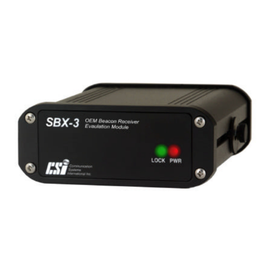
Figure 2-1). When the red LED, labeled ‘PWR’, is illuminated, the Evaluation Module is receiving 9-40 VDC from an external power source. When the SBX-3 acquires a lock on a beacon transmission, the green LED, labeled ‘LOCK’, will illuminate. Figure 2-1 Evaluation Module LED Indicators... -
Page 36: Evaluation Module Interface Connections
2.3 SBX-3 Evaluation Module Interface Connections The Evaluation Module is easily installed, requiring only power, data, antenna, and ground connections. Figure 2-2 illustrates the required interface. Caution – By default, the Evaluation Module provides 10 VDC across the antenna port. Connection to incompatible devices may result in damage to equipment. -
Page 37: Evaluation Module Default Settings
Level Voltage RS-232C 4800 10 VDC 2.5 Installing the SBX-3 Evaluation Module To ensure optimum performance and ease of operation, observe the following considerations when installing the Evaluation Module. 2.5.1 Placement The Universal Mounting Bracket (U-bracket) supplied with the evaluation kit is used to secure the receiver to the selected mounting surface. -
Page 38: Environmental Considerations
The Evaluation Module’s power LED remains illuminated while power is applied. Table 2-2 Evaluation Module Power Requirements Input Input Current Input Power Voltage 9-40 VDC 140 mA @ 12 VDC 1.7 W SBX-3 Reference Manual... -
Page 39: Grounding The Evaluation Module
Caution - Do not operate the Evaluation Module with the 1.5 A fuse bypassed. 2.5.4 Grounding the Evaluation Module For best performance and RF noise mitigation, connect the SBX-3 Evaluation Module to a counterpoise ground. The back plate of the Module includes a grounding point, labeled ‘GND’, to which you may connect a 14+ gauge insulated electrical wire. -
Page 40: Rs-232C Interface Level
2.6.2 RS-422 Interface Level When operating at the user selectable RS-422 interface level, you will have access to only the main serial port of the SBX-3 engine. Table 2- 4 provides pin-assignment information for the data port of the SBX-3 Evaluation Module at the RS-422 interface level. -
Page 41: Evaluation Module / Gps Receiver Interface
Please note that the RS-422 interface level must have both positive and negative signals connected in order to communicate. The transmit line from the GPS engine to Port 0 of the SBX-3 does not need to be connected unless the GPS engine is able to configure the SBX-3 using NMEA commands. -
Page 42: Figure 2-3 Evaluation Module Interface, Rs-232C
Figure 2-4 illustrates the interface for a GPS receiver operating at the RS-422 communications level. Please note that when using the RS- 422 option of the Evaluation Module, only the main serial port of the SBX-3 is accessible. SBX-3 Evaluation GPS Receiver... -
Page 43: Changing The Interface Level
R X + Figure 2-4 Evaluation Module Interface, RS-422 For successful communications, the baud rate of the SBX-3 must be set to match that of the GPS receiver. Section 3.7 describes the default communication settings of the SBX-3. Refer to Section 5.6.2 to change the baud rate of the SBX-3 using proprietary NMEA commands. -
Page 44: Figure 2-5 Evaluation Module Rs-232/Rs-422 Configuration
RS-422 level. The interface level corresponding to the switch position is silk-screened onto the circuit board. Caution – The SBX-3 and its Evaluation module are electrostatic sensitive devices. Observe proper precautions when handling components during this procedure. Damage caused to the receiver by ESD is not covered under warranty. -
Page 45: Antenna Output Voltage
Jumper JP1 of the Evaluation Module allows you to select whether the output voltage to the external antenna is +5 VDC or +10 VDC (See Figures 2-5 and 2-6). The CSI Wireless MBA-3 and MBA-3A whip antennas require an input voltage between 10 and 13 VDC, while the MBL-3 loop and MGL-3 combination antenna can operate with a voltage input between 4.9 and 13 VDC. -
Page 46: Figure 2-7 Abx-3/Mbx-3 Internal Signal Splitter Option
For integrators pursuing the SBX-3 receiver within their design, CSI Wireless will provide documentation to incorporate the CSI Wireless Signal Splitter within the integration upon the signing of an agreement. Please contact your CSI Wireless Sales representative for further information. -
Page 47: Oem Beacon Receiver
‘PWR’ silk-screening and the other is for indication of signal acquisition, labeled with ‘LOCK’ silk-screening. When power is applied to the SBX-3, the power LED illuminates and when the SBX-3 achieves signal acquisition on a valid DGPS beacon, the lock LED illuminates. -
Page 48: Block Diagram
The Digital Signal Processor (DSP) demodulates GPS correction information from the digital stream. The output of the SBX-3 is RTCM SC-104 DGPS correction data at a 5V HCMOS interface level. Figure 3-2 illustrates this process. -
Page 49: Mechanical Layout
Local Oscillator RTCM Output and NMEA Control Input / NMEA Status Output Memory Figure 3-2 SBX-3 Block Diagram 3.3 SBX-3 Mechanical Layout Figure 3-3 details the physical layout of the SBX-3 Beacon Receiver, including dimensions, and key components. SBX-3 Reference Manual... -
Page 50: Connector Pin Assignments
Figure 3-3 SBX-3 Mechanical Drawing 3.4 SBX-3 Connector Pin Assignments The SBX-3 has two header connectors designated as J1 and J2, labeled with on-board silk-screening. The J1 connector is a 1 x 4 pin header with 0.1” spacing that provides antenna power input, and signal distribution. -
Page 51: Antenna Interface
- Or - • Connect Pin 1 and 2 of SBX-3 connector J2 to the associated power supply (+5 or +12 VDC) and connect the power ground to pin 21, 22, 23, or 24 of Pin 4 of connector J1 is internally connected to Pins 1 and 2 of connector J2. -
Page 52: Signal Lock Indicator Pin
Figure 3-4 Lock Indicator Circuit 3.4.3 Reset Pin Pin 20 of connector J2 may be used to reset the SBX-3. Activating the reset circuit of the SBX-3 results in the same effect as cycling the input power to the receiver. The operating configuration of the receiver... -
Page 53: Dual Serial Port Overview
Figure 3-5 Reset Switch Circuit 3.5 SBX-3 Dual Serial Port Overview The SBX-3 features two full duplex serial ports (Port 0 and Port 1). Use of the second serial port is an option as the SBX-3 supports identical functionality as its predecessor, the SBX-2 on Port 0. -
Page 54: Dual Serial Port Operation
DB9 sockets at the opposite end. One of the DB9 sockets is labeled Port 1 for the SBX-3’s primary port and the other Port 2 for the SBX-3’s secondary port. Both of these two terminations will allow you to plug directly into a PC computer’s communication port. -
Page 55: Figure 3-6 Evaluation Module Connectivity, Rs-232C
N M E A N M E A 2 T X 1 2 T X 1 R T C M R T C M G N D G N D NMEA I/O Device Figure 3-6 Evaluation Module Connectivity, RS-232C SBX-3 Reference Manual... -
Page 56: Operating Modes
3.6.1.1 ABS Global Search When powered for the first time in ABS mode, the SBX-3 initiates a Global Search (GS), examining each available DGPS beacon frequency, and recording Signal Strength (SS) measurements in units of dBµV to the Global Search Table. - Page 57 DGPS broadcast, while the second channel continues searching in the background for superior beacon signals. If no signal is available, the SBX-3 will initiate a fresh Global Search, continuing this cycle until it finds a valid beacon. The secondary acquisition phase of the GS composes the remainder of the time required to acquire the beacon signal.
-
Page 58: Manual Mode
The SBX-3 stores the current primary beacon in memory so that it is available upon subsequent power-up. You may force a new Global Search at any time using the $PCSI,4<CR><LF> proprietary NMEA 0183 command defined in Section 5.6.2.1. 3.6.2 Manual Mode... -
Page 59: Integration Summary
The following steps summarize the general requirements for integration the SBX-3, and identify the command and control features provided: 1. SBX-3 Power Input - Apply a 5 VDC ±5% power input to Pin 3 of J2 with the power return connection at Pin 21 of J2. - Page 60 $PCSI,SBX~3 P003-5 2 Channel DGPS Version 008 $PCSI,F3040,0,R100,0,C0,0 $PCSI,F2835,0,R100,0,C1,0 6. When powered for the first time, the SBX-3 will operate in the default ABS mode and will conduct a Global Search to identify the highest quality beacon signal. Following the signal acquisition phase of the Global Search and when the primary receiver channel has acquired a beacon, the receiver’s second channel will conduct...
-
Page 61: Radio Frequency Immunity And Emissions
SBX-3 will attempt to reacquire the last station to which it was tuned. In Automatic mode, the SBX-3 will try to lock to this station for 10 seconds before initiating a fresh Global Search to identify valid beacons. If set to... - Page 62 SBX-3 Reference Manual...
-
Page 63: Antenna Installation
Ensure that the antenna is lower than the highest metal object on the vessel to protect against precipitation static and lightning strikes. When positioning the antenna, the following procedure will help minimize interference to the beacon receiver. SBX-3 Reference Manual... -
Page 64: Installation
To implement this procedure, a valid beacon signal must be available at your location. A PC computer is required to monitor the performance status messages output by the SBX-3 as discussed in Chapter 5. • Turn off the vehicle or vessel (if present), and all electrical accessories. - Page 65 The MBA-3 requires a 50 Ω impedance antenna extension cable such as RG-58U (up to 150 m (492 ft) in length) for proper operation. For proper performance, connect the MBA-3/MBA-3A to a counterpoise ground (artificial) as illustrated in Figure 4-1. SBX-3 Reference Manual...
-
Page 66: Figure 4-1 Receiver & Mba-3/Mba-3A Grounding Requirement
When removing the BNC termination from the MBA- 3A cable, be sure to note the configuration of the various parts within the connector so that they can be re-installed in the same order. SBX-3 Reference Manual... -
Page 67: H-Field Antenna
Performance may be improved with the antenna mounted beneath the aircraft. The ABL-1 requires a 50 Ω impedance antenna extension cable such as RG-58U (up to 150 m (492 ft) in length) for proper operation. The ALB-1 does not require an antenna ground connection. SBX-3 Reference Manual... -
Page 68: Combined Gps/Beacon Antenna
8 cm (3 inches) above the metal surface upon which it sits. Connect the grounding bolt of the MGW -1 to a counterpoise (artificial) ground using 14+ gauge insulated electrical wire in the same manner as is required by the MBA-3 and MBA-3A antennas. SBX-3 Reference Manual... -
Page 69: Routing And Securing The Antenna Cable
Plug the AM/FM antenna into the AVL-1 port labeled ‘AM/FM Antenna’ • Plug the port labeled ‘AM/FM Radio’ into the AM/FM radio • Connect the SBX-3 Evaluation Module to the AVL-1 port labeled ‘Beacon receiver’ • Use tie-wrap, hook and loops, or a similar mechanism to mount the AVL-1 in a convenient location. -
Page 70: Optional Antenna Mounts
Other cable materials with lower loss characteristics at GPS frequencies are available if you require a longer cable run. For more information on cable length, please contact your CSI Wireless dealer or CSI Wireless Customer Service. When choosing a route for the antenna extension cable, consider the following recommendations: •... -
Page 71: Permanent Mount
3, MGL-3, and MGW-1 antennas. It converts the standard 1-14-UNS- 2B thread to a 5/8 -inch thread frequently used with survey equipment (P/N 676-0005-xxx). This survey adapter is the same part as used for the shaft of the magnetic mount SBX-3 Reference Manual... -
Page 72: Nmea 0183 Interface
5. NMEA 0183 Interface This chapter identifies the selection of NMEA 0183 command and status query messages valid for the SBX-3 receiver. 5.1 Interface Protocols The SBX-3 supports the following data, command, and status protocols: • RTCM SC-104 differential GPS message protocol •... -
Page 73: Nmea Message Elements
PC computer. Please contact your dealer, or CSI Wireless Customer Service for more information. If you are using CSI Wireless's DGPS Command Center program, the Terminal window allows you to issue any of the NMEA commands, appending each sentence automatically with a <CR> <LF> when the... -
Page 74: Supported Nmea Messages
CSI Wireless’s World Wide Web site at www.csi-wireless.com 5.4 Supported NMEA Messages Both ports of the SBX-3 support the NMEA commands and queries listed in Table 5-2. The second serial port of the SBX-3 recognizes the same NMEA commands and queries as the primary serial port, however, the difference between the two ports is that Port 1 does not output RTCM data. -
Page 75: Response Message
The intent of this acknowledgement is to verify that the SBX-3 has received the NMEA sentence and acted appropriately. Descriptions of the response messages specific to each command and query are provided below the related command in the following sections. -
Page 76: Standard Commands
When this message is acknowledged by the SBX-3, it will immediately tune to the frequency specified and demodulate at the rate specified. When the ‘n’ field is set to a non-zero value, the SBX-3 will output the $CRMSS message at that period through the serial port from which the SBX-3 was tuned. - Page 77 When this message is acknowledged by the SBX-3, it will immediately tune to the frequency specified and demodulate at the rate specified. When the ‘n’ field is set to a non-zero value, the SBX-3 will output the $CRMSS message at that period through the serial port from which the SBX-3 was tuned.
- Page 78 $CRMSS message will not impact the output of RTCM on the main port. However, when tuning the SBX-3 with a non-zero ‘n’ field through the primary port, the NMEA status message will be interspersed within the RTCM data.
-
Page 79: Proprietary Commands
Global Search to identify candidate stations in the area, followed by the acquisition phase of the initial search. When the ‘n’ field is set to a non-zero value, the SBX-3 will output the $CRMSS message at that period through the serial port from which the SBX-3 was tuned. -
Page 80: Table 5-3 Sbx-3 Baud Rates
$PCSI,5,rP0,rP1<CR><LF> Response: $PCSI,ACK,5,rP0,rP1<CR><CL> In this message, rP0 designates the SBX-3 main serial port baud rate and rP1 designates the SBX-3 secondary serial port baud rate. Select your desired baud rate according to the supported rates shown in Table 5-3:... -
Page 81: Nmea 0183 Queries
This section discusses the standard and proprietary NMEA 0183 queries accepted by the SBX-3. It is important to note that when issued to the SBX-3 primary communications port, the response messages will be output interspersed with RTCM correction information. This may cause conflicts with a GPS receiver’s ability to compute differential corrected... - Page 82 The following subsections describe the selection of valid standard NMEA-0183 queries, and their responses. 5.7.1.1 Receiver Operating Status Query ($GPCRQ) This standard NMEA query prompts the SBX-3 for its operational status. It has the following format: $GPCRQ,MSK<CR><LF> Response: $CRMSK,fff.f,X,ddd,Y,n*CS SBX-3 Reference Manual...
- Page 83 RTCM data from the main serial port, when the receiver has acquired a lock on a beacon station. 5.7.1.2 Receiver Performance Status Query ($GPCRQ) This standard NMEA query prompts the SBX-3 for its performance status: $GPCRQ,MSS<CR><LF>...
-
Page 84: Proprietary Queries
5.7.2 Proprietary Queries The following subsections describe the selection of valid CSI Wireless proprietary NMEA-0183 queries, and their responses. 5.7.2.1 Receiver Help Query ($PCSI,0) This command queries the SBX-3 for a list of available proprietary $PCSI commands: $PCSI,0<CR><LF> Response: $PCSI,ACK,0 $PCSI,P003-0K,012 $PCSI,0 ->HELP Msg... - Page 85 Field Description Channel 0 PXXX- Resident SBX-3 firmware version Y.YYY SBX-3 receiver serial number fff.f Channel 0 current frequency Frequency Mode (‘A’ – Auto or ‘M’ – Manual) MSK bit rate RTCM rate Signal strength Signal to noise ratio Message throughput Quality number {0-25} –...
- Page 86 When querying the primary receiver channel using the secondary serial port, no interruptions in RTCM data output will occur on the primary port, provided the SBX-3 has acquired a valid beacon. 5.7.2.3 Status Line B, Channel 1 ($PCSI,2) This query commands the SBX-3 to output a selection of parameters related to the operational status of its secondary channel.
- Page 87 When querying the secondary receiver channel using the secondary serial port, no interruptions in RTCM data output will occur on the primary port, provided that SBX-3 has acquired a valid beacon. 5.7.2.4 Receiver Search Dump ($PCSI,3) This query commands the SBX-3 to display the search information used for beacon selection in Automatic Beacon Search mode.
- Page 88 $PCSI,79,3225,000,06,00,-0010,80,3230,339,0E,00,-0013,81,3235,000,06,00,-0011 $PCSI,82,3240,000,06,00,-0010,83,3245,202,0E,00,-0007,84,3250,006,0E,00,-0002 The SBX-3 will return this response when queried for its search table contents. The xx field is the frequency ID (1=283.5 to 84=325.0 kHz), ffff is the frequency in kHz multiplied by 10, sid is the station ID, ci is the receiver channel information, snr is the signal to noise ratio in dB, and ss is the signal strength in dBµV/m.
-
Page 89: Firmware Updates
5.8 Firmware Updates Please contact CSI Wireless Customer Service for the latest firmware update for your SBX-3 receiver. Firmware releases include a Field Upgrade Program, installation instructions, and release notes. SBX-3 Reference Manual... - Page 90 SBX-3 Reference Manual...
-
Page 91: Troubleshooting
6. Troubleshooting Use the following checklists to troubleshoot anomalous SBX-3 or Evaluation Module operation. Table 6-1 provides a problem symptom, followed by a list of possible solutions for troubleshooting operation of the SBX-3. Table 6-1 Troubleshooting Symptom Possible Solution •... - Page 92 • Non-differential GPS output Verify SBX-3 lock status • Verify matched SBX-3 output and GPS RTCM input baud rates • Verify GPS receiver RTCM compatibility • Verify GPS receiver DGPS configuration • Verify pin connectivity between SBX- 3/Evaluation Module and GPS receiver •...
-
Page 93: Appendixa - Specifications
PPENDIX PECIFICATIONS This appendix provides the operational, mechanical, electrical, physical, and environmental specifications for the following CSI Wireless products: • the SBX-3 OEM Beacon Receiver • the SBX-3 Evaluation Module • the MBA-3/MBA-3A whip Antenna • the MBL-3 Loop Antenna •... -
Page 94: Table A-2 Sbx-3 Evaluation Module Specifications
Specification Storage Temperature -40°C to 80°C Operating Temperature -30°C to 70°C Humidity 95% Non-Condensing Table A-2 SBX-3 Evaluation Module Specifications Operational Specifications Item Specification Frequency Range 283.5 - 325 kHz Channels 1.5 µV for 10 dB SNR @ 200 bps MSK Rate Input Sensitivity (into a 50 Ω... - Page 95 51 mm (2.0”) Weight 0.64 kg (1.4 lb) Antenna Connector BNC Socket Optional GPS Signal Output Connector TNC Socket Environmental Spe cifications Item Specification Storage Temperature -40°C to 80°C Operating Temperature -30°C to 70°C Humidity 95% Non-Condensing SBX-3 Reference Manual...
-
Page 96: Table A-3 Mba-3/Mba-3A Whip Antenna Specifications
Storage Temperature -40°C to 80°C Operating Temperature -30°C to 70°C Humidity 100% Condensing Table A-4 MBL-3 Loop Antenna Specifications Operational Specifications Item Specification Frequency Range 283.5 - 325 kHz Gain 34 dB Pre-Amplifier Integral Low Noise Amplifier SBX-3 Reference Manual... -
Page 97: Table A-5 Mgl-3 Combined Loop / Gps Antenna Specifications
Table A-5 MGL-3 Combined Loop / GPS Antenna Specifications Operational Specifications Item Specification Frequency Range, Beacon 283.5 - 325 kHz LNA Gain, Beacon 34 dB Pre-Amplifier, Beacon Integral Low Noise Amplifier Frequency Range, GPS 1.575 GHz (L1) LNA Gain, GPS 30 dB nominal SBX-3 Reference Manual... -
Page 98: Table A-6 Abl-1 Aircraft Antenna Specifications
Table A-6 ABL-1 Aircraft Antenna Specifications Operational Specifications Item Specification Frequency Range 283.5 - 325 kHz Gain 34 dB Pre-Amplifier Integral Low Noise Amplifier Power Specifications Item Specification Input Voltage 10-13 VDC supplied by receiver Input Current 30 mA SBX-3 Reference Manual... -
Page 99: Table A-7 Antenna Signal Splitter Specifications
70 dB typical, 58 dB min. Power Specification Item Specification Port J1 Input Voltage +10 VDC from beacon receiver Port J2 Output Voltage +10 VDC to combo. antenna (MGL-3) Port J3 Output Voltage N/A, DC blocked to GPS receiver SBX-3 Reference Manual... -
Page 100: Table A-8 Mgw-1 Combined E-Field / Gps Antenna Specifications
LNA Gain, Beacon 20 dB Pre-Amplifier, Beacon Integral Low Noise Amplifier Frequency Range, GPS 1.575 GHz (L1) LNA Gain, GPS 30 dB nominal Power Specifications Item Specification Input Voltage 4.9-13 VDC supplied by receiver Input Current 50 mA SBX-3 Reference Manual... -
Page 101: Table A-9 Avl-1 Automotive Beacon Coupler Specifications
Operational Specifications Item Specification Frequency Range, Beacon 283.5 - 325 kHz LNA Gain, Beacon 20 dB AM/FM Gain None required Power Specifications Item Specification Input Voltage +12 VDC supplied by beacon receiver Input Current <20 mA nominal SBX-3 Reference Manual... - Page 102 20.3 cm (8.0”) pigtail with Motorola Female connector Beacon Output BNC socket AM/FM Output 20.3 cm (8.0”) pigtail with Motorola Male connector Environmental Specifications Item Specification Storage Temperature -40°C to 80°C Operating Temperature -30°C to 70°C Humidity 100% Condensing SBX-3 Reference Manual...
-
Page 103: Appendixb - Beacon Information
• Reference station ID • Field Strength • Operating notes This document is viewable within your Internet browser, however, if you require a faxed copy of this information, contact your CSI Wireless dealer or CSI Wireless Sales. SBX-3 Reference Manual... - Page 104 SBX-3 Reference Manual...
-
Page 105: Further Reading
1800 Diagonal Rd, Suite 600, Alexandria, VA, 22314-2840 USA, Tel: +1- 703-684-4481, Fax: +1-703-836-4429 US Department of Transportation, United States Coast Guard, Broadcast Standard for the USCG DGPS Navigation Service, COMDTINST M16577.1, April, 1993, 2100 Second St. SW, Washington, D.C., 20593-0001, USA SBX-3 Reference Manual... - Page 106 SBX-3 Reference Manual...
-
Page 107: Index
MBL-3 Loop Antenna, 11, 44, 45 MGL-3 Combination Antenna, 12, E-Field Whip Antenna, 11, 42 Automatic Beacon Search (ABS), 54 Electro Magnetic Interference (EMI), Background Search, 36 Baud Rate, 17, 23, 37 Global Search, 35, 36, 55 GPS, 3 Grounding SBX-3 Reference Manual... - Page 108 Manual, 36 Lock Pin-out Example Circuit, 31 SBX-3, 29 Indicator Pin Assignment, 31 SBX-3 Evaluation Module, 20 Power Cable Fuse, 19 MBA-3 Whip Antenna, 11 MBA-3/MBA-3A Whip Antenna, 42 Range, 7 MBL-3 Loop Antenna, 11, 44, 45 Range Rate, 8...
- Page 109 RTCM SC-104, 3, 9, 28, 30, 31, 39, 49 Temperature, 18 SBX-3, 9 Troubleshooting, 65 SBX-3 Block Diagram, 28 SBX-3 Mechanical Layout, 28 SBX-3 Receiver, 27, 28, 29, 30, 31, 37, 38, 39 U-Bracket, 18 Selective Availability (SA), 2, 8 Splitter, 13, 25 www.csi-wireless.com, xvii...
- Page 110 SBX-3 Reference Manual...
Need help?
Do you have a question about the SBX-3 and is the answer not in the manual?
Questions and answers