Advertisement
Quick Links
Advertisement

Related Manuals for Invixium TFACE


Summary of Contents for Invixium TFACE
- Page 1 INGUIDE Quick Start Guide TFACE...
- Page 2 Invixium Customer Portal Stay up to date with: ▪ Latest Updates ▪ Best Practices ▪ Datasheets ▪ Installation Guides ▪ Feature Description Documents ▪ Videos ▪ FAQs ▪ Tutorials ▪ And more... Visit https://www.invixium.com/support/...
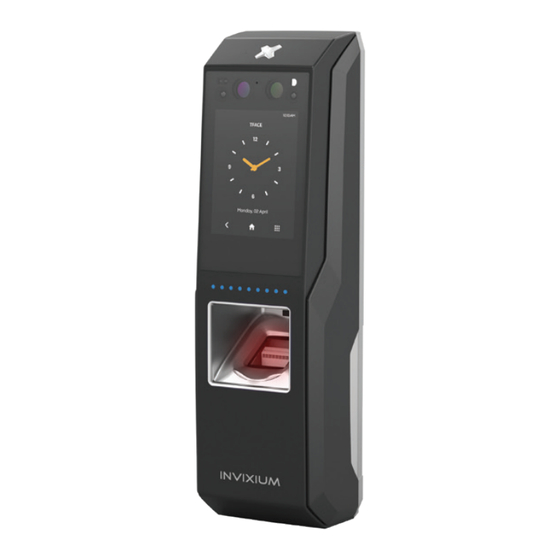
- Page 3 In the Box IXM INSTALL KIT Wall Mounting Screws (qty 4) Snubber Diode Wired Back Cover Dolphin Crimps (qty 12) Metal Mounting Plate Screw (qty 1) Micro USB Extension Cable (4 ft/1.2m) USB Cover Screw Gangue Box (qty 1) Mounting Screws Ferrite Core Hex Key (qty 2)
-
Page 4: Getting Started
Remove the Mounting Plate, Wired Back Cover and Screws from the IXM INSTALL KIT. Install the Mounting Plate at the desired location (Invixium recommends 120 to 125 cms from the floor to the bottom of the device). Make the necessary connections to the Wired... - Page 5 Get Wired Glossary Top Connector 7 9 11 13 15 17 19 Access Control Panel Relay Receiver Common Door Access Control SGND Signal Ground DGND Digital Ground Specific Purpose Input 8 10 12 14 16 18 20 Door Strike Power Specific Purpose Output Bottom Connector EGND...
- Page 6 Get Wired Top Connector Wire Color Wire Label Pin(s) Wire Color Wire Label Pin(s) Red/White USB0_VBUS Orange/Yellow SPO_1 Blue RS485_D+ Black/Red SGND RJ 45 White/Grey USB0_D- 13-20 TCP/IP Receptacle Blue/Black RS485_D- Green/Grey USB0_D+ Blue/Red RS485_T Black/White USB0_GND Orange/White RS232_RX Yellow/Cyan SPI_1 Purple/White RS232_TX...
- Page 7 Get Wired Bottom Connector Wire Color Wire Label Pin(s) Wire Color Wire Label Pin(s) VIN+ Blue/White DAC_IN3 Green/Yellow EGND Black/Green DGND Black VIN- Brown ACP_LED1 Grey/Red RLY_NO Green WDATA_OUT0 Black/Green DGND Yellow ACP_LED2 Grey RLY_COM White WDATA_OUT1 Black/Green DGND White/Purple DAC_IN1 White/Red RLY_NC...
-
Page 8: Earth Ground
Earth Ground Earth Ground Wire Lug For protection against Electrostatic Discharge, Invixium recommends the use of a ground connection between each IXM device to a high quality Earth Ground available at the install site. Connect to Earth Ground in the following way:... - Page 9 Ensure that a regulated, filtered and dedicated power source provides a minimum of 12VDC @ 2A per device, when using an external power supply. PoE+ connectivity is also available on all TFACE models. When using PoE+, an IEEE 802.3at compliant Active Midspan Recommended PoE+ Injector Specs Injector or switch is required (sold separately).
- Page 10 RS-485 Configuration For RS-485 networks, ensure that devices are wired in a daisy chain configuration, up to a maximum of 31 devices. At a baud rate of 9600 bps, make certain that the maximum cable length is not longer than 1200 m (4000 ft). IXM WEB RS-485 to USB Converter...
- Page 11 Serial Communication and USB For Serial Communication, IXM devices are equipped with RS-232 and USB capabilities. Refer to Get Wired Top Connector page for RS-232 connections. The USB port can be used to connect a Flash Drive via Micro USB OTG cable and perform functions like upgrading firmware, downloading transaction logs and configuration files.
- Page 12 Wiegand 2 3 4 5 6 7 8 9 10 11 12 13 14 15 16 17 18 19 20 21 22 23 24 25 26 27 28 29 30 31 32 33 34 Standard 26-Bit Wiegand Format IXM devices have the option to use the Facility Code (8 Bits) ID (16 Bits)
- Page 13 ACP Connections TFACE ACP_LED1 ACP_LED2 WDATA_OUT0 WDATA_OUT1 Bottom Connector DGND (13) ACP_LED1 WDATA_OUT0 (14) (15) ACP_LED2 WDATA_OUT1 (16) ACP_LED signals can be used if available on the Access Control Panel. IXM DGND (17) devices support up to 2 wires for LED status.
- Page 14 DAC Connections (Electric Door Strike) TFACE RLY_NO Electric Snubber Diode RLY_COM Door Strike Door Strike Power Supply DAC_IN1 Door DAC_OUT Contact DAC_OUT Bottom Connector Request DAC_IN2 to exit RLY_NO RLY_COM DAC_IN1 DAC_IN2 Max Relay rating = 24VDC @ 2A DAC_OUT...
- Page 15 DAC Connections (Magnetic Lock) TFACE RLY_NC Magnetic Snubber Diode RLY_COM Door Lock Door Strike Power Supply DAC_IN1 Door DAC_OUT Contact DAC_OUT Request Bottom Connector DAC_IN2 to exit RLY_COM DAC_IN1 RLY_NC Max Relay rating = 24VDC @ 2A DAC_IN2 DAC_OUT (19)
- Page 16 DAC Connections (Device Powers Door Strike) TFACE RLY_NO Electric Snubber Diode RLY_COM Door Strike Note: If the device is powering a magnetic DGND lock, please use RLY_NC wire as shown on the previous page. DAC_DSP DAC_IN1 Door Contact DAC_OUT Bottom Connector...
- Page 17 Face Enrollment Best Practices Invixium recommends standing at a distance of 1.5 to 3 feet from the device when enrolling a face. Make sure your entire face is in the centre of the screen. The user should look straight at the camera when enrolling their face. Avoid looking in other directions or turning your head during enrollment.
- Page 18 Fingerprint Enrollment Best Practices Incorrect Correct Pressure Too Low Too High Good Position Rotation Condition Preferred Fingers Good...
- Page 19 Finger Placement Best Practices 1. Proper finger placement is crucial for good enrollment score and faster authentication. 2. Place your finger straight on the sensor as shown below, while covering the sensor with the top third of your finger as shown on the previous page. Incorrect Correct...
-
Page 20: Card Placement
Card Placement 1. For IXM TFACE, the card reader is placed below the fingerprint sensor. 2. See below for the correct card placement while using the IXM TFACE. -
Page 21: Software Installation
Read the guidelines and Click “Proceed”. Fill in all the details and Submit the form. An email with the link to download the latest IXM WEB package will be sent to the email ID provided. Extract the compressed file and run IXM WEB.exe. INVIXIUM recommends to select Install option for rapid installation. - Page 22 INGUIDE For technical or customer support issues, please contact your Local Authorized Reseller first. Visit the Customer Portal for more Invixium resources at www.invixium.com/support Enjoy the Experience. Some features may vary based on device models. Copyright © 2022, INVIXIUM. All rights reserved.
Need help?
Do you have a question about the TFACE and is the answer not in the manual?
Questions and answers
i want to have the latest Firmware for the device TFACE FP2
You can obtain the latest firmware for the Invixium TFACE FP2 device by visiting the Invixium Customer Portal at [www.invixium.com/support](https://www.invixium.com/support). The portal provides access to the latest updates, best practices, datasheets, installation guides, feature descriptions, FAQs, and more.
This answer is automatically generated