Advertisement
Quick Links
Advertisement

Subscribe to Our Youtube Channel
Related Manuals for Taik T210A


Summary of Contents for Taik T210A
- Page 1 T210A Instruction Manual Senflow T210A TAIK PROG 07/2020...
-
Page 2: Hardware Structure
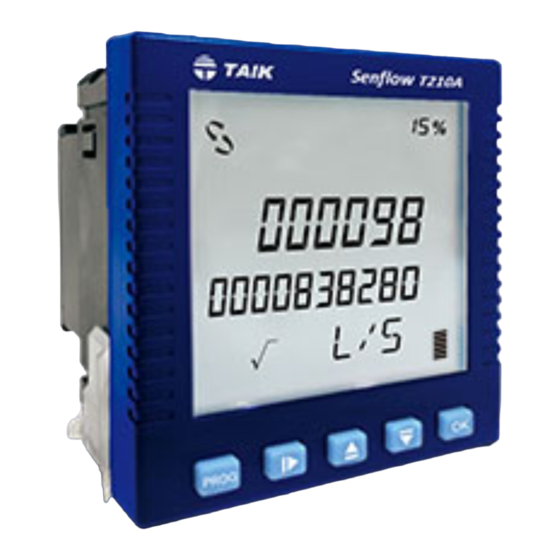
1. Hardware Structure: 1.1Push Buttons On Front Panel: 1.2 Terminals Configuration: Senflow T210A TAIK √ PROG Flow input indication flashes interactive 6 digits value display Power supply Parameters display symbol Signal input Tens digit accumulative value display Aux. power option... - Page 3 2. Installation/ Wiring: 2. Connection Diagrams 2.1 Case Dimension and Panel Cut-out: Unit:mm Rear view Meter connection Side view Cut-out size (+)(-) Analog Input Aux. Source +0.5 -0.0 Module Pulse and Analog output RS-485 relay contact MD01 MD06 MD07 +0.5 -0.0 A+ B- O 1G 1A 2G...
- Page 4 T210A Display Mode: : Keys Operation Advanced to the previous display Advanced to the next display PROG Access to the set-up page and enter password 瞬間功率與 & Instantaneous flow N on-resettable 不可歸零能量累計值 Non-resettable integrated flow integrated flow Clear integrated values at T1...
- Page 5 3.2 Formula Calculation 3.4 Error Code Mass flow rate calculation: W = Q * DS ERR1 OVERFD :Instantaneous flow exceed set value W:Mass flow rate(kg/s) Q:Volume flow rate(m³/s) ERR2 OVER P :Pulse output exceed available output range DS:Density of fluid (kg / m³) :...
- Page 6 4. Set-up Page Flowchart: Buttons: 4.1 Menus Flowchart Main menus Sub-menus Values set-up Vary value Advance to the last page Advance to the last page Vary value Advance to the next page Advance to the next page PROG Default code is 1000 Access to Sub-menus PROG PROG...
- Page 7 Communication set-up RELAY,Pulse set- up PROG PROG Set to PuLse 000000 0. 001 00.0.0 0.1 PuLSE 999999 9. 999 Pulse corresponding value Address R1 Output set-up ulse corresponding options Pulse width Pulse corresponding value decimal point position Set to OFF 19200 9600 4800...
- Page 8 4.2 Menu Legends: LCD backlight set-up ON:LCD backlight stays on 4mA and 20mA corresponding value dEFuLT:LCD backlight shut down after 10 secs.when not in use Range: 0.0001~99999 OFF:Close LCD backlight Enter corresponding Backlight set-up value Correction factor set-up : A coefficient can correct deviation Intantaneous flow decimal point Range: 00.001~99.999 Range: .0000~0000...
- Page 9 output corresponding value R1 output option OFF:output disable, PuLSE:pulse output OFF:No output, FLOW:flow Analog output set-up R1 Output set-up Pulse corresponding options AO1 4mA corresponding value KWH:power, L:flow Range: 000000~999999 Ao1 4mA ulse corresponding options Corresponding value Ao1 20mA corresponding value Pulse corresponding value decimal point position Range: 000000~999999 Range: 000001~00.0001...
- Page 10 R2 output option OFF:output disable, EALAM:Will activate when error happens RS-485 communication address set-up RELAY:Set point activation Range:001~199 R2 Output option set-up Rs485 address set-up R2 activation set-up point RS-485 baud rate set-up ≧:more than or equal to set value 2400,4800,9600,19200 ≦:less than or equal to set value Relay activation set point...
-
Page 11: Specifications
5. Specifications: Specifications Display screen: Analog output: Format LCD white backlit Output range DC4- 20mA isolated Instantaneous flow digits 5 digits Corresponding value Instantaneous flow Integrated flow digits 10 digits Status symbol Relay contact status, RS-485 communication status ≦350Ω Maximum load Pulse output,Analog output percentage ±0. -
Page 12: Emc Testing
Application environment: Operating temperature 0-60°C EMC Testing Operating humidity 5-95% RH,non condensing Conducted emission Storage temperature -10- 70°C EN 55011 Radiated emmission EN 55011 Characteristic and terms: Harmonic current emissions Sampling time 0.3 secs. EN 61000-3-2 Ingress protection Ip54 front,IP20 rear Voltage changes, voltage fluctuations,and flicker Dielectric strength Input/ Output/ Power AC2KV,1min... -
Page 13: Rtu Mode
6. Communications: 6.1 Communication protocol: 6.6 Writing Register Command: A single writing WORD command Adopting MODBUS communication shall use a repeater as the meters Query: are in parallel connection more than 30 pcs. Start of Address Functio Start Start Value Value Erro r En d of... - Page 14 6.8 The CRC Calculation: static unsigned char auchCRCHi[]={ 0x00,0xc1,0x81,0x40,0x01,0xc0,0x80,0x41,0x01,0xc0, The CRC is calculated on all byte of a message from the Address Filed to the 0x80,0x41,0x00,0xc1,0x81,0x40,0x01,0xc0,0x80,0x41, last data byte ended (Data Field); Furthermore, it means that the data 0x00,0xc1,0x81,0x40,0x00,0xc1,0x81,0x40,0x01,0xc0, 0x80,0x41,0x01,0xc0,0x80,0x41,0x00,0xc1,0x81,0x40, received is in error if the CRC calculation performed on host does not match 0x00,0xc1,0x81,0x40,0x01,0xc0,0x80,0x41,0x00,0xc1, the received data.
- Page 15 6.9 Setting Data Address 6.9.1 Communication address Address (Hex) Format Codename Access Range & Unit Address (Hex) Format Codename Access Range & Unit Contents Contents 0~9999 9 9 9 9 9 9 Integer 0~ 3 0000 0000H (Note 1) T2.A 0032 0020H Instantaneous flow decimal point Note 3...
- Page 16 6.9.2 Notes Address (Hex) Format Codename Access Range & Unit Note Contents Description 0064 0040H Integrated value byte order from high to low is DCBA, if using tens digit calculation, D * 2^48 + C * 2^32 + B * 2^16 + A the i ntegrated value: 0065 0041H...
Need help?
Do you have a question about the T210A and is the answer not in the manual?
Questions and answers