
Related Manuals for Taik T250


Summary of Contents for Taik T250
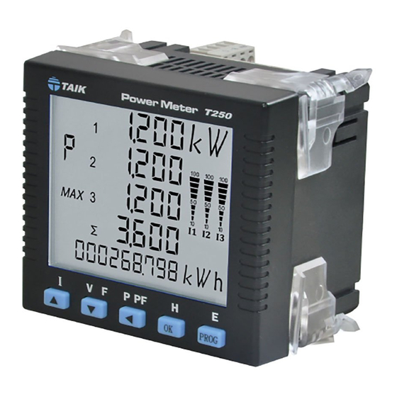
- Page 1 T250 Instruction Manual TAIK Power Meter T250 100 100 100 P PF PROG...
- Page 2 1 4 rows of 4 digits Front View 2 Inductive/capacitive load or positive/ negative value Values in line-neutral or line-line voltage TAIK Power Meter T250 :L1 Value :L1-2 Voltage (line to lin) :System Value 4 Measured electrical parameters 120 120 120...
- Page 3 2.2 Connection Diagrams: 3 Phase 4 Wire (3 PTs, 3 CTs) 3 Phase 3 Wire (2 PTs, 2 CTs) 1K 1L 2K 2L 3K 3L 1K 1L 2K 2L 3K 3L Aux. Power Aux. Power 1 Phase 3 wire (Only 2 CTs) 3 Phase 4 Wire (Only 3 CTs) 1K 1L 2K 2L...
- Page 4 3. Functions of Buttons: 3.1 Keys Programming 3.1.1 Symbols of Phase Sequence (Refer to 1.1) Display: 4 digits at the maximum figures up to 9999 Display Decimal point position of The M/K unit: The position of the Current demand and max. current demand decimal point in the M/K unit will automatically be varied with the rated inputs (CT and PT ratio set-up) Values in line-neutral or line-line voltage:...
- Page 5 3. Display Mode and Button Functions : Appearing the bargraph rate at % for the measured current on each display 3.2 Display in 3P4W: Current Volt/Frequency VA/W/Var/PF/Demand Energy Individ. harmonic rate/THD P PF PROG 100 100 100 100 100 100 100 100 100 100 100 100 100 100 100...
- Page 6 Appearing the bargraph rate at % for the measured current on each display 3.3 Display in 3P3W: Current Volt/Frequency VA/W/Var/PF/Demand Individ. harmonic rate/THD Energy P PF PROG 100 100 100 100 100 100 100 100 100 100 100 100 100 100 100 line-line/ system voltage phase/ system currents phase/ system active power...
- Page 7 Appearing the bargraph rate at % for the measured current on each display 3.4 Display in 1P3W: Current Volt/Frequency VA/W/Var/PF/Demand Energy Individ. harmonic rate/THD P PF PROG 100 100 100 100 100 100 100 100 100 100 100 phase/system currents phase/system active power phase/system THD voltage line-neutral/ system voltage...
- Page 8 Appearing the bargraph rate at % for the measured current on each display 3.5 Display in 1P2W: Energy Current Volt/Frequency VA/W/Var/PF/Demand Individ. harmonic rate/THD P PF PROG 100 100 100 電壓及頻率顯示 current voltage/frequency active power THD voltage P PF P PF PROG 100 100 100 max.memorized current...
- Page 9 4. Set-up Flowchart/ Buttons: 4.1 Set-up Flowchart: 4.2 Buttons: Functions: ※ Default value by factory setting to 1000 Password isn’t set to 0 ※ PROG Incorrect set-up returns the measured values Hold Main menus: and consequentially appears Access to sub-menus PROG Password is set to 0 Extended module ordered will...
- Page 10 4.3 Relay Contact & Analog Output (Extended modules) : ※Having an associated module can be shown on the screen, the I/O module is unavailable shown on the screen. Analog module Relay module Same function but different defined code Same function but different defined code 主功能表...
- Page 11 4.4 The reminders of Sub-Menus Set-up : Being applied to Double Words” transmission : The electrical connection shall correspond : with the set wiring configuration Hi word is set ahead, Low word is set behind It is defined as “Swapped Float” :...
- Page 12 5. Specifications: 5.1 Measured Parameters and Accuracy: THD % display: < Current 1% F.S. < Voltage 10% F.S. Display Accuracy L-L volt 0.2% Power supply: L-N volt 0.2% 85~265 AC/DC Auxiliary power supply Current 0.2% 20~60V (OPTION ) Active power 0.5% Reactive powe r 0.5%...
- Page 13 6.COMMUNICATIONS 6.1 Communication protocol 6.6 Writing Register Command: A single writing WORD command Query: Utilizing MODBUS communication shall use a repeater as the meters are in parallel Start Start connection more than 30pcs. Start of Address Function Value Value Error End of Address Address...
- Page 14 6.8 The CRC Calculation: static unsigned char auchCRCHi[]={ 0x00,0xc1,0x81,0x40,0x01,0xc0,0x80,0x41,0x01,0xc0, The CRC is calculated on all bytes of a mes sage from the address to the 0x80,0x41,0x00,0xc1,0x81,0x40,0x01,0xc0,0x80,0x41, last data byte inclusively. The CRC field is the result of a CRC calculation 0x00,0xc1,0x81,0x40,0x00,0xc1,0x81,0x40,0x01,0xc0, performed on the message contents.
- Page 15 6.9 Data Address: (Integers) 6.9.1 Set-up: (Hex) Address (Hex) Contents Format Word Access Range & Unit Address Contents Format Word Access Range & Unit 0042 002AH Ry3 Type Integer 0000 0000H Display Page Integer 0 - n (Note) 0 - 1 0043 002BH Ry4 Type...
- Page 16 6.9.2 Values: Floating Point, Word transmission refers to 485 CASE for set-up Access Range & Unit Address (Hex) Contents Format Word Address (Hex) Contents Format Word Access Range & Unit 4096 1000H Float 4188 105CH Maximum Float V_RN Float Maximum VL Float 4098 1002H...
- Page 17 6.9.4 Value: Integers 6.9.3 Values: Long Integers, Word transmission refers to 485 CASE for set-up Address (Hex) Contents Format Word Access Range & Unit Address (Hex) Contents Format Word Access Range & Unit V Unit Hour Scale 1F8H Integer See 6.9.5 100H Long V Dot...
- Page 18 6.9.4 Value: Integers 6.9.5 Unit and Decimal Point The received integer data as the primary values. And the set-up in unit and decimal point must be Range & Unit Address (Hex) Format Word Access completed after receiving data. * *The received values will be correct after the set-up in CT & PT ratio has completed. ** 225H VarH (Ind) Hi Word Integer...
Need help?
Do you have a question about the T250 and is the answer not in the manual?
Questions and answers