Table of Contents
Advertisement
Quick Links
Advertisement
Table of Contents

Related Manuals for CRE GENSYS COMPACT MAINS


Summary of Contents for CRE GENSYS COMPACT MAINS
-
Page 2: Table Of Contents
TECHNICAL DOCUMENTATION Table of contents Description ............................ 4 Front Face ............................... 4 Rear Face ..............................6 Panel Mounting ............................7 UL Requirements ............................9 Usage ..............................11 Password ............................... 11 LCD ............................... 12 Wiring ..............................14 Digital Inputs ............................19 Digital Outputs and Output Relays ...................... - Page 3 TECHNICAL DOCUMENTATION CAN bus Good Practices ........................103 Appendices ..........................105 ECU J1939 ............................105 Short Circuit Protection ......................... 113 Troubleshooting ............................ 120 Standards for Generator ........................124 Certifications ............................125 Software Variables ..........................126 A56_MAINS_A90020-L-E...
-
Page 4: Description
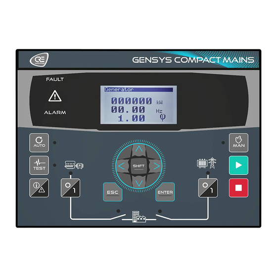
TECHNICAL DOCUMENTATION Description Front Face GENSYS COMPACT Mains Buttons Functions SHIFT button Additional functions. RIGHT button Navigation button (Right). DOWN button Navigation button (Down). LEFT button Navigation button (Left). UP button Navigation button (Up). ENTER button Validating entry / MENU. - Page 5 The voltage when the "AVR control" page is displayed. will increase/decrease the contrast of the LCD display. Note: Available only on GENSYS COMPACT PRIME and GENSYS COMPACT MAINS. Cancel setting and return to Navigation mode. Return to previous menu. Validation of the modified parameter and return to Accessing a menu / Switching to Edition mode.
-
Page 6: Rear Face
TECHNICAL DOCUMENTATION Rear Face GENSYS COMPACT Mains Simplified Wiring Diagram A56_MAINS_A90020-L-E... -
Page 7: Panel Mounting
Unpack and keep the packaging in case of return. Make sure the unit does not show scratches or visible defaults. Otherwise describe them on the RMA sheet (available on CRE TECHNOLOGY website) and return it with the product to your distributor. A56_MAINS_A90020-L-E... - Page 8 TECHNICAL DOCUMENTATION Installation Preparation · Torque of mounting brackets: 0.4Nm. · Cut out the panel to 220x160mm (8.7x6.3in) minimum. · Make sure the cut-out is smooth and clean. Mounting Tool : cross-heas screwdriver size 1 Pass the unit through the mounting surface In the rear, cover each of the four spacers using the 2 parts of the fixing kit.
-
Page 9: Ul Requirements
Device must be installed in an unventilated or filtered ventilation enclosure to maintain a pollution degree 2 environment. Maximum surrounding air temperature rating: 45°C. ADV ANCED WIRING DIAGRAM Wiring diagrams available on the website CRE TECHNOLOGY : GENSYS COMPACT MAINS HMI _ CORE - A56_MAINS_A90020-L-E... - Page 10 TECHNICAL DOCUMENTATION Standard wiring schematics Installation For information on installing the product, see chapter Panel Mounting. A56_MAINS_A90020-L-E...
-
Page 11: Usage
Used to change advanced 1234 Advanced settings settings. Passwords can be changed via CRE PC software: i4Gen Suite Software To access the Supervision menu, press To access the Settings menus, the padlock must be released: 1. Press to select Settings. -
Page 12: Lcd
TECHNICAL DOCUMENTATION Na vigation Press , then, select the required menu, then press and enter the level 1 password if necessary (Settings): A black pointer spots the currently selected item/setting. Two main menus are available on the LCD screen and three in i4Gen Suite Software: ·... - Page 13 TECHNICAL DOCUMENTATION Note: Correct the condition that triggered the protection before performing a reset; if necessary, the protection will trip again. Information These pages allow to display the power and engine current state with the associate elapsed time in this state. Power [4000] displays the unit current state regarding power management.
-
Page 14: Wiring
I/O wires (under 10V DC). If power and communication cables have to cross each other, do it at right angles to avoid crosstalk: Wiring diagrams available on the website CRE TECHNOLOGY : GENSYS COMPACT MAINS HMI _ CORE - Standard wiring schematics A56_MAINS_A90020-L-E... - Page 15 On GENSYS COMPACT PRIME, this input must be used only for the earth fault protection. · On GENSYS COMPACT MAINS and AMF COMPACT, if Mains power measurement is configured as "mA" or "Unused", this input can be used as an earth current measurement.
- Page 16 Compatible with most voltage regulators. Isolated from power supply. AVR output + Analog output ±10V to voltage regulator. AVR output – Common Twisted pair; length. < 5m (16ft) if unshielded, < 50m max if shielded. CAN1 : CRE-Link® Isolated CAN© bus, use twisted pair. A56_MAINS_A90020-L-E...
- Page 17 TECHNICAL DOCUMENTATION Block and mark Description Notes White wire with blue strip (when using a CRE TECHNOLOGY cable). CAN L Blue wire with white strip (when using a CRE TECHNOLOGY cable). CAN H Resistor - Strap to CAN H when inner resistor must be inserted (bus ends).
- Page 18 TECHNICAL DOCUMENTATION D+ wiring The D+ line of the alternator needs to be wired as shown below to ensure the magnetization of the field coil: A56_MAINS_A90020-L-E...
-
Page 19: Digital Inputs
TECHNICAL DOCUMENTATION Digital Inputs Several parameters can be configured for each digital input: · Label (only in i4Gen Suite Software) · Function · Direction · Validity · Timer ON · Timer OFF Label This is the name you give to the input. The name will be shown in the digital inputs, information, alarm, and fault screens if programmed accordingly. - Page 20 TECHNICAL DOCUMENTATION Dela ys For each input, two delays can be defined in 100ms steps between 0 and 6553s: Functions Each input can be configured. To access all functions, use i4Gen Suite Software. Function list is available in Software variables. A56_MAINS_A90020-L-E...
-
Page 21: Digital Outputs And Output Relays
TECHNICAL DOCUMENTATION Digital Outputs and Output Relays Several parameters can be configured for each digital/relay output: · Label (only in i4Gen Suite Software) · Function · Polarity (sometimes referred to as Direction) · Pulse length: 0 means no pulse · Timer ON Polarity Each output can be:... -
Page 22: Analog Inputs
TECHNICAL DOCUMENTATION Analog Inputs General analog input configuration 1. Label: Analog input's label (limited to 14 characters). 2. Type: Define the way you want to use your analog input (unused / analog input / digital input). The analog input configuration page changes according to the selected type. Type set to Unused No configuration available. - Page 23 You can use 1 or 2-wire analog sensors, or 1-wire or 2-wire logical sensors. CRE RECOMMANDATION: In each case you must always connect the "common" J6 to the "- Power Supply" J1 and also connect it to the engine block in the case of 1-wire sensor.
- Page 24 TECHNICAL DOCUMENTATION A-2 : 1 wire analog sensor WARNING The warranty will be void if the manufacturer's instructions are not respected. To act as a 0...20mA input or 4...20mA, connect the input with a 39Ω resistor between the analog input and the analog common.
- Page 25 TECHNICAL DOCUMENTATION Type set to Digital input 1. Function: Define the digital input function 2. Validity: Condition to take the digital input into account. 3. Polarity: Digital input's polarity 4. Delay: Delay until the input becomes active. How to connect digital sensors To mimic a digital input, connect the input to Power–...
- Page 26 TECHNICAL DOCUMENTATION Protections Available for analog inputs when sensor type is set to Custom. If sensor type is set to Water temperature or Oil pressure, refer to dedicated protections. Several parameters can be configured from the Controller settings/Protections/Other protections/Analog inputs: ·...
-
Page 27: Hysteresis Di
TECHNICAL DOCUMENTATION Hysteresis DI For a given Hysteresis DI, three different digital signals are required: · Two digital inputs are used respectively as low threshold and high threshold signals. · One digital output is used to control an equipment with hysteresis First, open the Controller settings/Inputs/Outputs/Digital inputs and select Hysteresis DI. -
Page 28: Hysteresis Ai
TECHNICAL DOCUMENTATION Hysteresis AI For a given Hysteresis AI, two different signals are required: · One analog input for the measure · One digital output for the hysteresis to activate First, open the Controller settings/Inputs/Outputs/Analog inputs and select Hysteresis AI. Each hysteresis proposes the following parameters: ·... -
Page 29: Settings
TECHNICAL DOCUMENTATION Settings Engine Internal start sequence During the start sequence, the module controls the prelub, preglow, crank and fuel outputs when proper conditions are met, whereas the protections are inhibited. This concerns all engine protections. Main start phases: The engine is considered as started when its speed reaches the crank drop out setting. The module checks if the speed of the engine is in an acceptable range (between 95% and 105% of the nominal time) during an amount of time set by variable [3469] to consider the speed as stable and get to the next sequence. - Page 30 TECHNICAL DOCUMENTATION Chronogram for Gas Engine Conditions before start-up Module monitors the oil pressure and water temperature: 1. Oil pre-lubrication check: the oil pressure must be OVER the threshold [3473]. 2. Water temperature check: the water temperature must be OVER the threshold [3474]. Setting thresholds to 0 prevent the module to check those conditions before start-up.
- Page 31 TECHNICAL DOCUMENTATION Starter With multiple starters, preset digital outputs to Crank2 and Crank3. The Starter number depends on the preset output number. The starters are attempted according to the starter numbers as far as the engine fails to start. Setting Label Description By default...
- Page 32 TECHNICAL DOCUMENTATION External automatic start MODULE Some engines are equipped with an ASM (Automatic Start Module). On start (AUTO/TEST/MAN mode), the module empowers it to energize the crank and fuel and to synthesize the engine events. The setup depends on the type of ASM: Step Presetting Connections to ASM...
-
Page 33: Speed/Voltage Control
If the calibration failed, an error message will be displayed to inform you about the source of the problem. Note: if the error message contains an error code, please contact CRE Technology for more information. Note: Easycalib configures only the analog speed output and analog voltage output of the product. In the case of... - Page 34 TECHNICAL DOCUMENTATION 3. Adjust the speed value on the speed governor to get the nominal frequency (typically 50Hz or 60Hz). 4. Connect the speed output and speed common terminals to the speed regulator. Adjust the offset parameter to obtain a frequency of 50Hz (or 60Hz). 5.
- Page 35 TECHNICAL DOCUMENTATION (increase/decrease speed by pulse and increase/decrease voltage by pulse) to the desired +Speed/-Speed and +V/-V outputs. A pulse is generated when the absolute value of the correction applied exceeds the dead band. The larger the correction signal ([4405] for speed and [4411] for voltage), the longer the pulses are and the shorter the time between each pulse is.
-
Page 36: Circuit Breakers
TECHNICAL DOCUMENTATION Circuit Breakers Circuit breaker operating modes Two logic outputs (relay or transistor) are used to control the circuit breakers - 1 for opening and 1 for closing. These outputs allow different types of circuit-breakers to be controlled. The settings are accessible from Controller settings/Inputs/Outputs/Breaker/Generator Breaker Controller settings/Inputs/Outputs/Breaker/Mains Breaker. - Page 37 TECHNICAL DOCUMENTATION Circuit breaker control mode Value Mode Circuit breaker chronogram 1: Continuous contact to open. 2: Positive pulse to close. 1: Continuous contact to open. 2: Continuous contact to close. 1: Under-voltage (MN) coil opening. 2: Pulse to close. 1: Under-voltage coil opening.
- Page 38 TECHNICAL DOCUMENTATION Pulse configuration The settings can be accessed from i4Gen Suite Software. Positive Pulse Controller settings/Inputs/Outputs/Breaker/Generator Breaker settings Mains breaker positive pulse found Controller settings/Inputs/Outputs/Breaker/Mains Breaker. For the positive pulse control of the Generator breaker, set the parameter [2301]. The parameter of the positive pulse control for the Mains breaker is [2314].
- Page 39 TECHNICAL DOCUMENTATION Configuration of circuit breaker commands Two logic outputs (relay or transistor) must be configured as described in the table below and connected to the circuit breaker. Function Description Close Generator circuit breaker control Closing the Generator circuit breaker (continuous, pulse, MNcoil). Open Generator circuit breaker control Opening the Generator circuit breaker (continuous, pulse, MNcoil).
-
Page 40: Synchronization
TECHNICAL DOCUMENTATION Synchronization Functioning The module launches the synchronization only if the Mains provides at least 80% of the nominal voltage. It manages a correction on frequency and voltage to go and stay on the acceptance windows (can be handled in Synchronization). - Page 41 TECHNICAL DOCUMENTATION DANGER RISK OF ELECTRIC SHOCK, EXPLOSION OR ARCING § The module may only be installed and maintained by qualified electricians. § Use personal protective equipment (PPE) § Follow good safety practices for electrical work. § Turn off the power before installing or replacing a fuse, and before installing the module. §...
- Page 42 TECHNICAL DOCUMENTATION Verification 1. Disconnect the Generator circuit breaker control output on the module. 2. Make sure that there is voltage on the Mains side. The Mains LED should be lit. 3. Press to be in MAN mode. Press (Mains breaker) in order to close the Mains breaker. The Mains breaker LED is lit.
- Page 43 TECHNICAL DOCUMENTATION your engine. Be cautious when modifying this setting. A56_MAINS_A90020-L-E...
-
Page 44: Load/Unload Ramp
TECHNICAL DOCUMENTATION Load/Unload Ramp Functioning After a synchronization, the module ramps up the Generator load (soft transfer) to avoid overload or a load impact (hard transfer). The module calculates the active power set-point according to the configuration (base load, peak shaving and No break change over). -
Page 45: Kw/Kvar Regulation
TECHNICAL DOCUMENTATION kW/kVAR regulation Functioning The module switches to the regulation mode on KW and on KVAR around its set-point after a load ramp. The KW setpoint is calculated differently depending on the following modes: Base load mode: Generator KW set-point. Peak shaving mode: Mains KW set-point. -
Page 46: Protections
TECHNICAL DOCUMENTATION Protections Functioning Protections are triggered by an internal or external event (alarms, faults, logic inputs, CAN bus loss, etc.). In order to protect the process, engine or alternator, an action must be associated with the events. These actions are of different kinds: ·... - Page 47 TECHNICAL DOCUMENTATION Action on alarm/fault: select Security (Hard shut down). Note: A physical disconnection of the circuit line of all starters, circuit breakers commands and fuel command has to be wired in the cabinet in addition of the module emergency stop management. Communication Alarm/Fault Description...
- Page 48 TECHNICAL DOCUMENTATION Alarm/fault reset To perform an alarm/fault reset: - Locally: - Remote: use the "Reset faults" input function. A56_MAINS_A90020-L-E...
-
Page 49: Events
TECHNICAL DOCUMENTATION Events Functioning Events are actions performed on the installation that can be monitored by the controller. They are managed in the same way as an alarm/fault, thus they can be seen in the History menu where all alarms/faults/events history is listed. -
Page 50: Control Loop Pid
TECHNICAL DOCUMENTATION Control Loop PID eMPIRICAL PID GAIN TUNING 1. Set all the gains to 0 (except G gain). 2. Increase the P gain until you have a stable oscillation. 3. Increase the D gain until the oscillation is canceled. 4. -
Page 51: Advanced Settings
TECHNICAL DOCUMENTATION Advanced Settings Droop Functioning In order to maintain load sharing, the droop is used in the case of the following CRE-Linkâ problems: · Isolated product (if [3052] is set to 8 or 9). · Missing product (if [3054] is set to 8 or 9). -
Page 52: Static Paralleling
TECHNICAL DOCUMENTATION Static Paralleling Cases STUDY · Starting a full plant with multiple generators in an emergency on dead bus: the generators are ready to take load in the shortest possible time, without warm-up. Bottom line: full plant availability in less than 10s typically. This meets the NEC700 requirements. ·... - Page 53 TECHNICAL DOCUMENTATION Sequence 1. Any signalling of Mains voltage loss activates the Remote start inputs. 2. The module opens the Mains breaker and closes the Generator breaker. 3. The module starts the engine and waits for the speed of the generator to be in the acceptable range (between 95% to 105% of the nominal speed).
-
Page 54: Load Shedding
TECHNICAL DOCUMENTATION Load Shedding Functioning The load shedding is the ability to disconnect less important consumers if the Power plant is overloaded even when the full capacity is engaged; this prevents a blackout. Any module – generally one – in the Power plant can take care of excessive demand. If the KW demand exceeds the Power plant capacity and/or the frequency has dropped below a threshold for a given time, the dedicated module activates outputs to shed non-essential loads. - Page 55 TECHNICAL DOCUMENTATION The charts show the trip alarm and trip outputs depending on the Generator load or frequency: The trip counter sums the times during which at least one consumer is shed. It is reset at the same time as the alarm: A56_MAINS_A90020-L-E...
-
Page 56: Maintenance Schedule
TECHNICAL DOCUMENTATION Maintenance Schedule The configuration of the maintenance schedule is carried out from the i4Gen Suite Software. The consultation is done in Controller supervision/Maintenance ("off" means that the servicing cycle is not defined). When a cycle has elapsed, an alarm is displayed and the module's alarm LED flashes. In the module alarm page you can view the expired cycle. -
Page 57: Synch & Load Share Only
"Synch & Load Share only" mode is proposed to transform a standard GENSYS COMPACT PRIME or COMPACT MAINS into an automatic synchronizer & load sharing unit in order to replace analog load sharing systems, analog synchronizers, or any systems combining both of these features (Such as Barber Colman PowRCon, CRE Unigen…) Once this mode is activated, the controller will only launch synchronization on request, and share load once it has received the paralleling information. - Page 58 TECHNICAL DOCUMENTATION [4501] & Mains breaker feedback [4500]) load control will be active. End of load sharing/load control Load sharing/load control process will be stopped when Remote start on load [4502] input is removed. The load will ramp down to the Low kW active power threshold [2866] (accessible in Controller settings/Electrical/Generator) and will deactivate the Generator breaker close [4675] output when the threshold is reached.
-
Page 59: Mains Application
TECHNICAL DOCUMENTATION Mains application In Mains paralleling applications, if a "Mains electrical fault" is managed (with protections or logic inputs), the Generator starts and takes the load when the Mains fail, even if the remote start is disconnected. In all cases, a Mains protection must be set to start the Generator if the Mains disappears. - Page 60 TECHNICAL DOCUMENTATION If a remote start is activated when the Mains is present, the Generator starts, opens the Mains breaker, closes the Generator breaker after a preset time and take the load. A56_MAINS_A90020-L-E...
- Page 61 TECHNICAL DOCUMENTATION Settings Variables Label Value [2005] To mains operation Change over [0]. [2009] Mains back timer Waiting times to ensure a stable return of the Mains. [2007] Change over time delay Operating mode 1. Press : the associated LED lights up. 2.
-
Page 62: No Break Change-Over
TECHNICAL DOCUMENTATION No break Change-over When the remote start is on, the Generator starts, synchronizes, parallels to the Mains and then takes the load (ramps up). Once the Mains is unloaded, the module opens the Mains breaker as described in the following figure: When remote start is off, the Mains takes the load in the same way as the Generator did previously. - Page 63 TECHNICAL DOCUMENTATION Settings Variables Label Value [2005] To mains operation Change over (Value = 0), No break change over (Value =1) and Permanent (value = 2). In No break change over mode, the Mains power set-point has to be reached during [2008] Mains low limit ramp down load before opening the Mains circuit breaker.
- Page 64 TECHNICAL DOCUMENTATION Note: MAN mode does not allow +/- fast or +/- voltage to synchronize or load control. In MAN mode, with circuit breaker open, the module can control the speed and voltage: Local key Substitution function Manual start / manual stop. For speed control, go to page Configuration/Engine.
- Page 65 TECHNICAL DOCUMENTATION AUTO AUTO mode requires using a logic input configured as Remote start. All sequences are managed automatically, as on previous picture. Failure to synchronize After a Mains fault, the Generator is alone on the load. When the Mains comes back and the return to Mains temporization is over, the module tries to synchronize to the Mains.
-
Page 66: Permanent
TECHNICAL DOCUMENTATION Permanent When the remote start is on, the module starts the Generator, synchronizes and parallels with the Mains, then ramps up load until it reaches its set-point. On base load mode, the Generator has a constant load and the Mains takes the utility load variations. If the utility load is less than the Generator set-point, the Mains is in reverse power. - Page 67 TECHNICAL DOCUMENTATION 3. Press (Generator breaker) to synchronize the Generator with the Mains and do a load ramp to the KW set-point (Generator KW set-point in Base Load or Mains KW set-point in Peak shaving). The Generator is in parallel with the Mains and provides active power according to its configuration: 1.
- Page 68 TECHNICAL DOCUMENTATION The “Operator controlled return to mains” special function allows the operator to control the moment the engine will return the load to the Mains. To do this, a digital input of the module should be set as “Manual mains back”. The unit will wait the synchronization order provided by the digital input before re-synchronizing the engine to the Mains.
-
Page 69: Advanced Functions
TECHNICAL DOCUMENTATION Advanced Functions Easy Flex® Easy Flex® offers a simple and innovative programming mode, allowing you to adapt the controller to your needs. This function is presented as a list of operations numbered from 1 to 50. Each line of this list corresponds to an operation between 2 values (see below) : V ariables Easy Flex®... - Page 70 TECHNICAL DOCUMENTATION 1. Available in reading and writing, this variable can be dropped in Result field. 2. Available in read only, this variable can not be dropped in Result field. A56_MAINS_A90020-L-E...
- Page 71 TECHNICAL DOCUMENTATION Operators and calculations Adding operators The list of operators is available in the left pane by clicking on the Operators tab (see below) : You can then drag and drop them into the Operator field provided for this purpose (see below) : Use of operators ·...
- Page 72 TECHNICAL DOCUMENTATION Adv anced functions for calculation operators Advanced features, such as execution conditions, are available by clicking on the setting icon located at the right of each line : Conditions These 2 functions (if equal and if not equal) allow you to execute the associated line only when the condition is met. Example: Here, the operation is executed if variable User variab.1 is equal to 0.
- Page 73 TECHNICAL DOCUMENTATION Adv anced functions for test operators Advanced features, such as execution conditions, are available by clicking on the setting icon located to the right of each line : Timers Timers are available only on calculation lines that contain a test operator . Example with a function that contains a Timer : The test result is updated if the test is validated for 10 seconds.
- Page 74 TECHNICAL DOCUMENTATION User variable 1 now takes the value 0 if GE U31 is HIGHER than GE U23. The NOT function is used to invert the boolean result. Easy Flex® warning Variable [4214] provides more information in case of an Easy Flex® warning alarm. This is how variable [4214] is calculated: [4214] = (100 * line concerned) + type of error Here are the different types of errors:...
-
Page 75: User Variables
TECHNICAL DOCUMENTATION User variables A range of user variables is available to be used in equations. Starting from firmware v2.22, this range has been split into two sub-ranges: · Saved user variables [8000 to 8049] · Unsaved user variables [8050 to 8099] Unsaved user variables are set to 0 when the unit is powered on while Saved user variables values are saved in non volatile memory so their values are kept even in case of power loss. -
Page 76: Alternative Selection
TECHNICAL DOCUMENTATION Alternative selection The Alternative Selection menu offers a supplement to Easy Flex® programming. This function is presented as 16 selections between two values. Adding v ariables The variables that can be added to the list are available on the left of the screen. To add new variables from the list of variables, click on the + button (see below) : Use the search engine to find and select the variables you want to use. - Page 77 TECHNICAL DOCUMENTATION · When Alt select 1 = 1 then NominalVoltage will be set to 2000. Please note that if a variable is used in an alternative selection, modifying this variable from front face, Modbus and any other source will always result in its value being overwritten by the alternative selection. A56_MAINS_A90020-L-E...
-
Page 78: Scheduler
TECHNICAL DOCUMENTATION Scheduler The scheduler can activate any function that can be controlled by a digital input. These functions can be activated one or many times. Scheduled items are presented as a list. Each line (item) in this list corresponds to a scheduled event. Scheduler list In the Configuration/Programming/Scheduler page, you will have access to all events that you created. - Page 79 TECHNICAL DOCUMENTATION 6. Confirm or cancel the event settings. SCHEDULER Supervision Available in Supervision > Scheduler : 1. Number of the event. 2. Function active during the event. 3. Next time the event will take effect (be careful, not the same as the configuration because this one is actualised). 4.
-
Page 80: Modbus Tcp Mapping
TECHNICAL DOCUMENTATION Modbus TCP Mapping Configurable block To create your own Modbus blocks, use variables [10000]…[10299] in i4Gen Suite Software/Controller settings/Programming/Modbus/Modbus redirection. There are two ways to configure these blocks: 1. Configuration in i4Gen Suite Software/Controller settings/Programming/Modbus/Modbus redirection: enter the codes of the variables to read; Modbus readings on registers [10000]…[10299] will be the values of the pointed variables. -
Page 81: Logger
TECHNICAL DOCUMENTATION Logger The Logger tool is used to track value or status changes up to 10 variables at the user's choice. Power status and engine mode variables are always recorded as long as the logger is not set to Off. This function is available in i4Gen Suite Software/Controller settings/Programming/Logger. -
Page 82: Communications
TECHNICAL DOCUMENTATION Communications Network Setting up your PC connection Materials required: · A CAT 5 cross Ethernet cable (marked CROSSOVER CABLE along its sheath) for direct connection to the module from your computer. · A CAT 5 straight Ethernet cable (marked PATCH CABLE or STRAIGHT-THROUGH CABLE along its sheath) can only be used with an Ethernet switch. - Page 83 TECHNICAL DOCUMENTATION DHCP (automatic): The module supports DHCP. If DHCP is enabled, the module must be connected to a network equipped with a DHCP server to obtain an IP address. On power-up, the module obtains an IP address from the DHCP Server. If the DHCP protocol fails, the fixed IP address of the module is used (Factory setting: 192.168.11.1).
-
Page 84: Modbus Tcp/Ip
TECHNICAL DOCUMENTATION Modbus TCP/IP Abilities The complete list of variables is described in Software variables. Through Ethernet communication where the module acts as a Modbus slave, you can: · Upload many readings and module internal variables. · Download values for many module internal variables. Type Range Fault access right... - Page 85 TECHNICAL DOCUMENTATION Access rights The access rights depend on the parameter type and on Modbus access permissions. To manage access rights, set to 1 the corresponding bits in the word [3015]: Default Description Bit # value Writing to date/ time Writing to Engine counters Not used Writing to digital input function register...
- Page 86 TECHNICAL DOCUMENTATION Modbus communication example The table below shows a Modbus/TCP client sending a reading request (function 04) of 6 registers starting from variable [0079]. Client request Module server response Value Field Field Value Function code Required function. Starting Register (MSB) Data bytes (=2*Nb of registers requested).
-
Page 87: Canopen
When the engine protocol MTU MDEC is selected on port CAN2 of the controller, CANopen protocol is automatically switched to port CAN1 which is also used as inter-controller protocol CRE-Link® so all CANopen couplers are connected with all COMPACT controllers through a single CAN bus. - Page 88 TECHNICAL DOCUMENTATION An overflow alarm [609] is available for analog inputs. When it is active, you can look at [610] to know which analog inputs triggered the alarms. If you have several analog inputs causing a problem, you'll have to solve each problem one by one.
-
Page 89: Sae J1939
TECHNICAL DOCUMENTATION SAE J1939 Presentation J1939 is a CAN protocol used by “electronic” motors which include an ECU - Engine Control Unit, also called Engine Control Module (ECM) or Engine Management System (EMS). This protocol allows to read engine data (measurements, positions, binary values) and send commands (start, stop, speed control…). - Page 90 TECHNICAL DOCUMENTATION Also, the module shows the latest five unmanaged SPN (what is wrong)/FMI (Failure Mode Identifier, i.e. error type) combinations it has received through the diagnostic message (DM1). These SPN/FMIs are backed up in the following registers: Registers Description [0664] J1939 SPN LO 1 [0665]...
- Page 91 TECHNICAL DOCUMENTATION 171 FEF5 Ambient Air Temperature [728] 172 FEF5 Engine Intake 1 Air Temperature [729] 173 FEF6 Engine Exhaust Temperature [735] 174 FEEE Engine Fuel 1 Temperature 1 [715] 175 FEEE Engine Oil Temperature 1 [716] 176 FEEE Engine Turbocharger 1 Oil Temperature [717] 182 FEE9 Engine Trip Fuel [711]...
- Page 92 TECHNICAL DOCUMENTATION 1242 FE92 Instantaneous Estimated Brake Power [694] 1387 FE8C Auxiliary Pressure #1 [691] 1388 FE8C Auxiliary Pressure #2 [692] 1390 FE8B Engine Fuel Valve 1 Intake Absolute Pressure [690] 1761 FE56 Aftertreatment 1 Diesel Exhaust Fluid Tank Volume [785] 1800 FE50 SLI Battery 1 Temperature [784]...
-
Page 93: J1939 Custom Frames Settings
TECHNICAL DOCUMENTATION J1939 custom frames settings It is possible to set up custom J1939 frames in reception/transmission on the controller. configure J1939 custom frames, please open i4Gen Suite Software/Controller settings/Engine/J1939/J1939 ECU/ECM page. The Receive frame and Transmit frame tabs will be available only if J1939 protocol is enabled. A maximum of 10 received frames and 10 transmitted frames can be set. - Page 94 TECHNICAL DOCUMENTATION · PGN: the PGN of the J1939 data you want to read. It is possible to use both decimal or hexadecimal format. Filling one field will automatically update the other. Mapping · Destination: The controller's variable in which you want to store the received data. ·...
- Page 95 TECHNICAL DOCUMENTATION · Source: The controller's variable whose value will be sent. · Offset: The offset to apply to the controller's variable value before sending. · Resolution: The resolution to apply to the controller's variable value before sending. Note: The transmitted value will be equal to (Controller's variable value * Resolution) + Offset Datas ·...
-
Page 96: J1939 Sniffer
TECHNICAL DOCUMENTATION J1939 sniffer J1939 sniffer is a J1939 CAN frame recorder provided to check frames present on the J1939 network. The dedicated space allows for the storage of approximately 1000 to 1200 frames that can be retrieved in a text file. This text file will contain the list of the frames in the form of their 29 bits CAN identifiers 0 to 8 data bytes following a timestamp for each frame. -
Page 97: Mtu Mdec
TECHNICAL DOCUMENTATION MTU MDEC Presentation MTU MDEC is a complete engine monitoring and control system with a specific MTU MDEC ECU - Engine Control Unit - which can broadcast data values and error codes on a CAN bus. The ECU can detect faults and send them to the module: protections can be assigned to these faults (see below). Important information Attention MTU MDEC is proposed as a software option. - Page 98 TECHNICAL DOCUMENTATION MTU MDEC Description Variable 110002 Engine Speed (ECU) [1202] 110026 P-Lube Oil [1203] 110046 P-Fuel Note: this PV is not available on MTU MDEC CAN Module 302 [1204] 110049 P-Charge Air [1205] 110053 P-Fuel (Common Rail) [1206] 110126 T-Coolant [1207] 110131...
- Page 99 TECHNICAL DOCUMENTATION Recommended configuration (this is the default MTU MDEC ECU settings for most cases): · Use MDEC analog input (typically 0.5V...9.5V for 1500rpm +/-100rpm adjustment for 50Hz applications) · Set controller speed output offset to 5V so that the speed output without correction will match the 1500rpm speed demand input of the MDEC (for 50Hz applications).
-
Page 100: Modbus Client
TECHNICAL DOCUMENTATION Modbus client Overview A Modbus/TCP client is implemented in the product in order to communicate with an external device that provides Modbus communication. You may send and retrieve data to and from a unit that is connected through Modbus/TCP or through Modbus RTU if you use a Modbus/TCP to RTU gateway between the devices. - Page 101 TECHNICAL DOCUMENTATION · Transmission: an internal variable is computed and sent into a remote register. You may setup up to 10 reception and 10 transmission lines. Click on the '+' button at the top left corner of the page to add a new reception/transmission line, or click on an existing line in order to modify its setup.
- Page 102 TECHNICAL DOCUMENTATION Useful information Determining the proper gain when reading values It is possible to always use the same formula to determine the gain (as long as the values are linear) for a value you're reading: gain = value expected / value read via Modbus When reading values, do not forget to set the accuracy (and optionally the unit if there is any.
-
Page 103: Can Bus Good Practices
The following table shows the maximal length of a CAN bus depending on the bit rate: Bit rate (Kbits/s) Maximal length (m) 5000 2500 1000 The next table lists the standard bit rate of each CAN protocol that can be used by a CRE TECHNOLOGY unit: A56_MAINS_A90020-L-E... - Page 104 Bit rate (Kbits/s) Note CRE-Link® 125kbits/s recommended. Can be changed using parameter CAN1 CANopen [3050]. same as CRE- (if MTU MDEC protocol Link® selected on CAN2) 250 for J1939 Switches automatically to the right speed when selecting an J1939 / MTU MDEC 125 for MTU ECU protocol with [3118].
-
Page 105: Appendices
TECHNICAL DOCUMENTATION Appendices ECU J1939 CATERPILLAR Manufacturer [3100] ECU [3101] Air + Exhaust + Alternator Oil and coolant GENERIC [0] A4E2 (C4.4 C6.6)[1] 91 515 250 157 183 168 158 247 102 105 106 172 92 513 ECU [3101] Speed Start/Stop Speed selection GENERIC [0]... - Page 106 TECHNICAL DOCUMENTATION ECU [3101] Speed Start/Stop Speed selection GENERIC [0] QSX15-G8 (CMS570) [1] CM850 [2] QSB5 (PGI 1.1) [3] QSB7 (PGI 1.1) [4] QSL9 (PGI 1.1) [5] QSM11 (PGI 1.1) [6] QSX15 (CMS570) [7] QSK19 (PGI 1.1) [8] QSK38 (PGI 1.1) [9] QSK50 (PGI 1.1) [10] QSK60 (PGI 1.1) [11] DETRO IT DIESEL...
- Page 107 TECHNICAL DOCUMENTATION DEUTZ FAHR Manufacturer Air + Exhaust + ECU [3101] Fuel & ECU Oil and coolant [3100] Alternator GENERIC [0] EMR [1] 91 512 188 183 247 102 92 513 100 110 EMR2 [2] 102 105 92 513 98 100 110 111 91 512 183-4-8 174 158 108 247 91 512 2432 183 174 94 111 158 EMR3 [3]...
- Page 108 TECHNICAL DOCUMENTATION JO HN DEERE Manufacturer Air + Exhaust + ECU [3101] Fuel & ECU Oil and coolant [3100] Alternator GENERIC [0] 91 512 515 2432 182 250 183 107 52 106 102 105 101 98 100 175 109 110 111 JDEC [1] 184 94 157 174 158 247 173 176 81 92 513 514...
- Page 109 TECHNICAL DOCUMENTATION ADEC The SAM (Service and Automation module) is associated with the ADEC 2000 or ADEC 4000. The set is referred to as the ECU7. Disconnect X13 to turn off the power. Insert the CCB2 card into SAM slot #3. The ADEC ECU, SAM and the module communicate via 2 CAN buses: a CAN bus between the SAM and the ADEC with a proprietary protocol, a CAN bus between the module and the SAM with the J1939 protocol.
- Page 110 TECHNICAL DOCUMENTATION ECU8 Smart Connect is used for: · select the origin of the speed control via an 8 position selector · set droop frequency and slope Via the K1 connection box, the ECU8, the Smart Connect and the module are connected: a CAN bus between the Smart Connect and the ECU8 with a proprietary protocol, a CAN bus between the Smart Connect and the module with the J1939 protocol.
- Page 111 TECHNICAL DOCUMENTATION PERKINS Manufacturer Air + Exhaust + ECU [3101] Fuel & ECU Oil and coolant [3100] Alternator GENERIC [0] 1100 A4E 91 515 188 174 250 183 247 102 105 92 513 100 110 ECU [3101] Speed Start/Stop Speed change GENERIC [0] 1100 (A4E) SCANIA...
- Page 112 TECHNICAL DOCUMENTATION VO LVO PENTA Manufacturer ECU [3101] Fuel & ECU Air + Exhaust + Alternator Oil and coolant [3100] GENERIC [0] EMS2 [1] 94 182 250 247 102 172 100 175 110 EDC4 [2] Same as Deutz EMR2 Same as Deutz EMR2 Same as Deutz EMR2 94xGE [3] 91 512 188 1013 182 94 250...
-
Page 113: Short Circuit Protection
TECHNICAL DOCUMENTATION Short Circuit Protection The tripping time depends on the duration an alternator winding can endure an over current. A IDMT (Inverse Definite Minimum Time) curve is defined by: · a type (IEEE, IEC, IAC), · Is: current for infinite time in type 1 (asymptote value); type 1.2 is not used, ·... - Page 114 TECHNICAL DOCUMENTATION T curves with t=1 for I/Is=10: A56_MAINS_A90020-L-E...
- Page 115 TECHNICAL DOCUMENTATION A56_MAINS_A90020-L-E...
- Page 116 TECHNICAL DOCUMENTATION Inverse curves just above the pick-up value (not logarithmic abscissae I/Is) for various value of TMS: A56_MAINS_A90020-L-E...
- Page 117 TECHNICAL DOCUMENTATION IEEE CURVES Characteristic curve Moderately inverse 0.515 0.1140 0.02 Very inverse 19.61 0.491 Extremely inverse 28.2 0.1217 A56_MAINS_A90020-L-E...
- Page 118 TECHNICAL DOCUMENTATION HOW TO DERIVE A CURVE BY PARALLELISM Say a curve is known. We know tsA (s stands for the start curve) for IA/Is (s stands for set point). Two curves with same k, a and c are parallel: K= tsA/Ts10 = tA/T. This can be used to find tA. In the preceding curves in logarithmic plot, Ts10=1.
- Page 119 TECHNICAL DOCUMENTATION 1) Means only valid for IEC curves A56_MAINS_A90020-L-E...
-
Page 120: Troubleshooting
TECHNICAL DOCUMENTATION Troubleshooting To get a history of alarms-faults, stop the Generator, connect to i4Gen Suite Software/File transfer/Save file -> Log, and click Save. To restore factory settings into i4Gen Suite Software, navigate to Controller settings/System/Reset factory settings, and click Reset. Message "Oil pressure"... - Page 121 TECHNICAL DOCUMENTATION Error Messages When Transferring a File to the Module Note: "…" indicate a variable number, a label number or a text number according the error message. It will help you to locate your error in your configuration file. ERROR 001: Only when GENSET is STOP File transfer between computer and the unit should be done only when all conditions below are met i.e.
- Page 122 TECHNICAL DOCUMENTATION ERROR 024: Unit …. does not exist. Modifying this unit is not allowed. Check the unit number before sending the configuration file again. ERROR 025: Wrong accuracy value on …. (0,1,2 or 3) The value of the accuracy is out of range. The value must be between 0 and 3. ERROR 026: Wrong unit value on ….
- Page 123 TECHNICAL DOCUMENTATION Warning Warnings do not prevent the module to work but inform the user of a potential problem in its configuration file. WARNING 001: Wrong size of label …. WARNING 002: Wrong character entered in label …. WARNING 003: Wrong size of text …. WARNING 004: Wrong character entered in text ….
-
Page 124: Standards For Generator
TECHNICAL DOCUMENTATION Standards for Generator ISO 8528-1 CLASSES AND POWER DESIGNATIONS Various load-duration profiles are defined. Here is the correspondence between classes and powers: Power Conditions Conditions Controller designation designation GENSYS Allowable average power output over a Prime Running Overload: max: 1 h PRIME COMPACT 24-hour period is 70% of the prime... -
Page 125: Certifications
TECHNICAL DOCUMENTATION Certifications DECLARATION OF CONFORMITY Certifications are available for download as PDF files at www.cretechnology.com in the download area. A56_MAINS_A90020-L-E... -
Page 126: Software Variables
TECHNICAL DOCUMENTATION Softw are Variables A56_MAINS_A90020-L-E... - Page 127 Technical Documentation List of variables Dynamic ......................1 28 Speed control .
- Page 128 Technical Documentation Power up in mode [2012]............. . . 141 Test mode [2014] .
- Page 129 Technical Documentation Mains meters ................... . .148 Mains energy [120] .
- Page 130 Technical Documentation Engine/ECU/ECM ................... . 1 56 Engine .
- Page 131 Technical Documentation Timer ON Digital Input 2 [2710] ............163 Timer OFF Digital Input 2 [2719] .
- Page 132 Technical Documentation Timer ON hysteresis 4 [2780] ............169 Direction hysteresis 4 [2788] .
- Page 133 Technical Documentation Pulse length DO 3 [2763] ............. . 176 Activation delay DO 03 [2795] .
- Page 134 Technical Documentation CANopen DI 2 (Customizable label) ............182 CANopenVal I2 [3265] .
- Page 135 Technical Documentation CANopen DI 15 (Customizable label) ............188 CANopenVal I15 [3278] .
- Page 136 Technical Documentation CANopen DI 28 (Customizable label) ............195 CANopenVal I28 [3291] .
- Page 137 Technical Documentation CANopenModeO16 [3397] ............. 201 CANopen DO 17 (Customizable label) .
- Page 138 Technical Documentation CANopen Gain AI 05 [8359] ............206 CANopen Offset AI 05 [8358] .
- Page 139 Technical Documentation Over frequency control [2402]............213 Under frequency .
- Page 140 Technical Documentation Reverse kVAR ..................220 Reverse kVAR threshold [2427] .
- Page 141 Technical Documentation Current unbalance threshold [2492] ........... . 227 Current unbalance timer [2493] .
- Page 142 Technical Documentation Over voltage timer [2507] ............. . 235 Over voltage control [2508] .
- Page 143 Technical Documentation Maximum kVAR control [2526] ............242 Minimum kVar .
- Page 144 Technical Documentation Oil pressure timer [2363] ............. . . 250 Oil pressure control [2364] .
- Page 145 Technical Documentation Analog input 2 threshold 2 [2611] ........... . . 258 Analog input 2 timer 2 [2612] .
- Page 146 Technical Documentation Dynamic Speed control Variable Speed governor amplitude [2205] Unit Init value Min value Max value This parameter determines the amplitude of the speed output. Speed output voltage = Speed output offset + (Speed correction * Speed output amplitude). Ex : If the speed output offset is 5V and the amplitude is 2.5V, the speed output may vary between a minimum correction of 2.5V (5V + 2.5V) and a maximum correction of 7.5V (5V - 2.5V).
- Page 147 Technical Documentation Variable Frequency pulse divider [3652] Unit Init value Min value Max value This setpoint adjusts the ”pulse divider” in case of speed control by pulses. Description This pulse divider is able to change the response time of speed control by pulses. If you increase the value of pulse divider, you will decrease the time of pulse active.
- Page 148 Technical Documentation Variable AVR Offset [2252] Unit Init value Min value Max value This parameter determines the offset of the voltage output. Voltage output = Voltage output offset + (Voltage correction * Voltage output amplitude). Ex : If the voltage output offset is 5V and the amplitude is 2.5V, the voltage output can vary between a minimum correction of 2.5V (5V + 2.5V) and a maximum correction of 7.5V (5V - 2.5V).
- Page 149 Technical Documentation Synchronization PID Frequency Variable Frequency Global Gain [2900] Unit Init value Min value Max value This parameter multiplies the 3 components of the regulation (P, I and D). In most cases it is recommended to leave the default values of P, I and D and to change only this parameter. If the system seems too slow, increase this parameter.
- Page 150 Technical Documentation Variable Frequency Integral [2902] Unit Init value Min value Max value This parameter should only be changed if the system has not been correctly regulated by changing the Gain alone. In this case, refer to the chapter ”Control Loop PID” in the technical documen- tation of your product for a step-by-step method of adjustment.
- Page 151 Technical Documentation Phase Variable Phase Global Gain [2904] Unit Init value Min value Max value This parameter multiplies the 3 components of the regulation (P, I and D). In most cases it is recommended to leave the default values of P, I and D and to change only this parameter. If the system seems too slow, increase this parameter.
- Page 152 Technical Documentation Variable Phase Integral [2906] Unit Init value Min value Max value This parameter should only be changed if the system has not been correctly regulated by changing the Gain alone. In this case, refer to the chapter ”Control Loop PID” in the technical documen- tation of your product for a step-by-step method of adjustment.
- Page 153 Technical Documentation Voltage Variable Voltage Global Gain [2950] Unit Init value Min value Max value This parameter multiplies the 3 components of the regulation (P, I and D). In most cases it is recommended to leave the default values of P, I and D and to change only this parameter. If the system seems too slow, increase this parameter.
- Page 154 Technical Documentation Variable Voltage Derivate [2953] Unit Init value Min value Max value This parameter should only be changed if the system has not been correctly regulated by changing the Gain alone. In this case, refer to the chapter ”Control Loop PID” in the technical documen- tation of your product for a step-by-step method of adjustment.
- Page 155 Technical Documentation Variable kW/Freq Proportional [2909] Unit Init value Min value Max value This parameter should only be changed if the system has not been correctly regulated by changing the Gain alone. In this case, refer to the chapter ”Control Loop PID” in the technical documen- tation of your product for a step-by-step method of adjustment.
- Page 156 Technical Documentation Variable kW/Freq Derivative [2911] Unit Init value Min value Max value This parameter should only be changed if the system has not been correctly regulated by changing the Gain alone. In this case, refer to the chapter ”Control Loop PID” in the technical documen- tation of your product for a step-by-step method of adjustment.
- Page 157 Technical Documentation Variable kVAR/Voltage Proportional [2955] Unit Init value Min value Max value This parameter should only be changed if the system has not been correctly regulated by changing the Gain alone. In this case, refer to the chapter ”Control Loop PID” in the technical documen- tation of your product for a step-by-step method of adjustment.
- Page 158 Technical Documentation Variable kVAR/Voltage Derivate [2957] Unit Init value Min value Max value This parameter should only be changed if the system has not been correctly regulated by changing the Gain alone. In this case, refer to the chapter ”Control Loop PID” in the technical documen- tation of your product for a step-by-step method of adjustment.
- Page 159 Technical Documentation Variable Mains paralleling mode [2006] Unit Init value 0 : Peak shaving List values 1 : Base load This setpoint is used to select the mains paralleling mode if permanent paralleling has been selected. 2 setpoints can be used : Description - Peak Shaving (value 0) : Mains KW power setpoint.
- Page 160 Technical Documentation Variable Test active timer on [2015] Unit Init value 0 : No List values 1 : Yes This setpoint is used to activate a timer function for test mode. During this timer, the test mode Description is activated. At the end of this timer, the generator will stop, and product will be forced on auto mode.
- Page 161 Technical Documentation Variable Pre-start check fail timer [3454] Unit Init value Min value Max value 999.9 Maximum time to start (internal sequence : maximum prelubrification/external sequence : GE Description not ready) Variable Preglow [3456] Unit Init value Min value Max value 999.9 Description Glow plug warm-up time...
- Page 162 Technical Documentation Variable On load with timer [3478] Unit Init value 1800 Min value Max value 6553.5 Description Delay starting for a remote start with timer Stop sequence Variable Cooling [3470] Unit Init value Min value Max value 999.9 Description Cooling delay after shutdown request Variable Energize to stop timer [3472]...
- Page 163 Technical Documentation Variable Time before ignition [3480] Unit Init value Min value Max value 999.9 Description Time during which the starter is active without ignition Variable Ignition time on start [3481] Unit Init value Min value Max value 999.9 Description Ignition activation time at engine start Variable Ignition time on stop [3482]...
- Page 164 Technical Documentation Static paralleling Variable Waiting for deexcitation timer [2051] Unit Init value Min value Max value 999.9 Waiting time for the deexcitation of the alternator during a reexcitation sequence (Static paral- Description leling). The module will stop waiting for deexcitation when the time is up and will attempt to parallel the alternator to the bus/mains.
- Page 165 Technical Documentation Events Variable Power up [8300] Unit Init value 0 : No List values 1 : Yes Description Records controller power up event Variable Engine running state [8301] Unit Init value 0 : No List values 1 : Yes Description Records engine start and stop events Variable...
- Page 166 Technical Documentation Variable Generator KVARh [81] Unit kVarh Init value Min value Max value 4 294 967 295 Description Generator kVARH (lower bytes) Variable Generator Hours Run [83] Unit Init value Min value Max value 4 294 967 295 Description Generator run hours (lower bytes) Variable Start attempts [78]...
- Page 167 Technical Documentation Electrical Generator Generator Generator Variable Nominal active power [2105] Unit Init value Min value Max value 32 500 This setpoint adjusts the kW nominal power of the generator. All the electrical protections for kW Description on %, load sharing calculation or power management with the mains will be calculated around this nominal value.
- Page 168 Technical Documentation Variable PT ratio [2100] Unit Init value Min value Max value 655.35 This setpoint adjusts the PT ratio to adapt alternator voltage measurement on the module. This setpoint is calculated with Bus Voltage / voltage measurement on the controller. Description Example : Voltage on bus 20.000Vac / voltage on controller 100 Vac : value of PT ratio = 20.000/100 = 200.
- Page 169 Technical Documentation Variable Base load kW setpoint [2107] Unit Init value Min value Max value 32 500 This setpoint adjusts the kW level for the base load operation : kW level reach for the generator Description power during the Mains paralleling operation. Variable Power factor setpoint (inductive) [2253] Unit...
- Page 170 Technical Documentation Variable Nominal voltage [2152] Unit Init value Min value Max value 65 535 This setpoint adjusts the bus/mains nominal voltage U. Input a phase-phase voltage value for triphase and biphase, and a phase-neutral voltage value for monophase. All the electrical pro- Description tections for U on % will be calculated around this nominal value.
- Page 171 Technical Documentation Variable External MCB low kW trip [2156] Unit Init value 0 : No List values 1 : Yes This setpoint is used to activate an ”External MCB low kW trip” . With an external devices, which can detect 3 currents phases, we can use it to detect 0 kW per phases and provide a Description digital information to the controller.
- Page 172 Technical Documentation Variable Fail to synchronize timer [2803] Unit Init value Min value Max value 999.9 Description Timer max for synchronisation Variable Control on fail to synchronize [2804] Unit Init value 0 : Unused List values 3 : Alarm 4 : Fault (soft shutdown) Action performed on protection’s trigger.
- Page 173 Technical Documentation Variable Maximum load validation [3705] Unit Init value 0 : Disabled List values 1 : Enable Description Enables/Disables overload monitoring for non-essential load shedding Variable Maximum load threshold 1 [3703] Unit Init value Min value Max value Description First overload level Variable Maximum load threshold 2 [3704]...
- Page 174 Technical Documentation Variable Last trip out [2862] Unit Init value 0 : Unused List values 3 : Alarm 4 : Fault (soft shutdown) Action performed on protection’s trigger. Actions’ description is available in the technical docu- Description mentation. Engine/ECU/ECM Engine General Variable Engine type [3477]...
- Page 175 Technical Documentation Variable Speed setpoint [2207] Unit Init value 1500 Min value Max value 10 000 Enter the instruction of speed has to respect. The Engine do not exceed this set point. For an Description electricity network of 50Hz put 1500 rpm and for a electricity network of 60Hz put 1800 rpm. Variable Speed setpoint (2) [2208] Unit...
- Page 176 Technical Documentation Variable Warm up selection [3479] Unit Init value 0 : Nominal speed List values 1 : Idle speed When starting the engin,choice to select the warm up speed (0 = Nominal speed / 1 = Idle Description speed) . Check before start Variable Preheating coolant temperature threshold [3474]...
- Page 177 Technical Documentation Crank settings Variable Maximum starting attempts by starter [3461] Unit Init value Min value Max value Description Setting of the number of start for one starter. Variable Time between start attempts [3458] Unit Init value Min value Max value 999.9 Description Timer between each cranking...
- Page 178 Technical Documentation Variable Crank 1 drop out [3462] Unit Init value Min value Max value 10 000 Description number of rpm max to drop out the starter. Variable Crank 2 drop out [3463] Unit Init value Min value Max value 10 000 Description Crank 2 drop out...
- Page 179 Technical Documentation Variable ECU type [3101] Unit Init value Description Choose the model of your ECU. If your ECU is not in the list, choose ”Generic” . Variable Units of measurement [3117] Unit Init value 0 : Bar, C, L/h °...
- Page 180 Technical Documentation Variable Polarity NO/NC on DI 1 [2736] Unit Init value Min value Max value Description Direction of Digital Input 1 (0=Normaly Open/1=Normaly Close) Variable Validity on DI 1 [2727] Unit Init value Min value Max value Digital Input 1 activation validity (0=Never/1=Always/2=Post Starting/3= rpm & Volt Stabi- Description lized) Variable...
- Page 181 Technical Documentation Variable Timer ON Digital Input 2 [2710] Unit Init value Min value Max value 6553.5 Description Digital Input 2 activation timer Variable Timer OFF Digital Input 2 [2719] Unit Init value Min value Max value 6553.5 Description Digital Input 2 desactivation timer Input 3 (Customizable label) Variable Polarity NO/NC on DI 3 [2738]...
- Page 182 Technical Documentation Input 4 (Customizable label) Variable Polarity NO/NC on DI 4 [2739] Unit Init value Min value Max value Description Direction of Digital Input 4 (0=Normaly Open/1=Normaly Close) Variable Validity on DI 4 [2730] Unit Init value Min value Max value Digital Input 4 activation validity (0=Never/1=Always/2=Post Starting/3= rpm &...
- Page 183 Technical Documentation Variable Timer ON Digital Input 5 [2713] Unit Init value Min value Max value 6553.5 Description Digital Input 5 activation timer Variable Timer OFF Digital Input 5 [2722] Unit Init value Min value Max value 6553.5 Description Digital Input 5 desactivation timer Input 6 (Customizable label) Variable Polarity NO/NC on DI 6 [2741]...
- Page 184 Technical Documentation Input 7 (Customizable label) Variable Polarity NO/NC on DI 7 [2742] Unit Init value Min value Max value Description Direction of Digital Input 7 (0=Normaly Open/1=Normaly Close) Variable Validity on DI 7 [2733] Unit Init value Min value Max value Digital Input 7 activation validity (0=Never/1=Always/2=Post Starting/3= rpm &...
- Page 185 Technical Documentation Variable Timer ON Digital Input 8 [2716] Unit Init value Min value Max value 6553.5 Description Digital Input 8 activation timer Variable Timer OFF Digital Input 8 [2725] Unit Init value Min value Max value 6553.5 Description Digital Input 8 desactivation timer Input 9 (Customizable label) Variable Polarity NO/NC on DI 9 [2744]...
- Page 186 Technical Documentation Hysteresis DI Hysteresis DI 1 Variable Hysteresis 1 enable for DI [2769] Unit Init value 0 : No List values 1 : Yes Description Enable hysteresis 1 on digital inputs functions Variable Timer ON hysteresis 1 [2777] Unit Init value Min value Max value...
- Page 187 Technical Documentation Hysteresis DI 3 Variable Hysteresis 3 enable for DI [2771] Unit Init value 0 : No List values 1 : Yes Description Enable hysteresis 3 on digital inputs functions Variable Timer ON hysteresis 3 [2779] Unit Init value Min value Max value 999.9...
- Page 188 Technical Documentation Hysteresis DI 5 Variable Hysteresis 5 enable for DI [2773] Unit Init value 0 : No List values 1 : Yes Description Enable hysteresis 5 on digital inputs functions Variable Timer ON hysteresis 5 [2781] Unit Init value Min value Max value 999.9...
- Page 189 Technical Documentation Hysteresis DI 7 Variable Hysteresis 7 enable for DI [2775] Unit Init value 0 : No List values 1 : Yes Description Enable hysteresis 7 on digital inputs functions Variable Timer ON hysteresis 7 [2783] Unit Init value Min value Max value 999.9...
- Page 190 Technical Documentation Analog inputs Hysteresis AI 1 Variable Activating Hysteresis on Analog Input 1 [2657] Unit Init value 0 : No List values 1 : Yes Description Enable hysteresis on analog input 1 with thresholds E2660(Low Level) & E2663(High Level) Variable Low level threshold [2660] Unit...
- Page 191 Technical Documentation Hysteresis AI 2 Variable Activating Hysteresis on Analog Input 2 [2658] Unit Init value 0 : No List values 1 : Yes Description Enable hysteresis on analog input 2 with thresholds E2661(Low Level) & E2664(High Level) Variable Low level threshold [2661] Unit °...
- Page 192 Technical Documentation Hysteresis AI 3 Variable Activating Hysteresis on Analog Input 3 [2659] Unit Init value 0 : No List values 1 : Yes Description Enable hysteresis on analog input 3 with thresholds E2662(Low Level) & E2665(High Level) Variable Low level threshold [2662] Unit Init value Min value...
- Page 193 Technical Documentation Digital/relays outputs Digital outputs Output 1 (Customizable label) Variable Polarity NE/ND DO 1 [2751] Unit Init value Min value Max value Description Polarity (0=Normaly De-energized / 1=Normaly Energized) Digital output 1 Variable Pulse length DO 1 [2761] Unit Init value Min value Max value...
- Page 194 Technical Documentation Output 3 (Customizable label) Variable Polarity NE/ND DO 3 [2753] Unit Init value Min value Max value Description Polarity (0=Normaly De-energized / 1=Normaly Energized) Digital output 3 Variable Pulse length DO 3 [2763] Unit Init value Min value Max value 6553.5 Description...
- Page 195 Technical Documentation Output 5 (Customizable label) Variable Polarity NE/ND DO 5 [2755] Unit Init value Min value Max value Description Polarity (0=Normaly De-energized / 1=Normaly Energized) Digital output 5 Variable Pulse length DO 5 [2765] Unit Init value Min value Max value 6553.5 Description...
- Page 196 Technical Documentation Relay outputs Relay 1 (Customizable label) Variable Direction NO/NC Relay 1 [2759] Unit Init value Min value Max value Description Relay 1 Direction (0=Normaly Open / 1=Normaly Closed) Variable Pulse length R 1 [2767] Unit Init value Min value Max value 6553.5 Description...
- Page 197 Technical Documentation Breaker General Variable Attempts number [2807] Unit Init value Min value Max value Number of attempts for an electrical fault. When an electrical fault is detected, the module Description automatically tries to close its breaker to see if the fault has disapeared. If it isn’t the case the module will try again until it has reached the number set in this variable Variable Delay before new attempt [2806]...
- Page 198 Technical Documentation Pulse Variable Gen CB control Pulse length [2301] Unit Init value Min value Max value Description Generator circuit breaker pulse length Variable Undervoltage coil hold time GCB [2302] Unit Init value Min value Max value Description Generator circuit breaker : timer of the negative impulsion when low voltage coil Variable Undervoltage coil security timer GCB [2303] Unit...
- Page 199 Technical Documentation Variable Undervoltage coil hold time MCB [2315] Unit Init value Min value Max value Description Mains circuit breaker : timer of the negative impulsion when low voltage coil Variable Undervoltage coil security timer MCB [2316] Unit Init value Min value Max value Description...
- Page 200 Technical Documentation Variable CANopenTM I1 [3232] Unit Init value Min value Max value 6553.5 Description Function execution delay, user can add execution delay after logic input status change Variable CANopenDir I1 [3296] Unit Init value Min value Max value Description Direction of logic input Normally open or Normally closed CANopen DI 2 (Customizable label) Variable...
- Page 201 Technical Documentation Variable CANopenTM I3 [3234] Unit Init value Min value Max value 6553.5 Description Function execution delay, user can add execution delay after logic input status change Variable CANopenDir I3 [3298] Unit Init value Min value Max value Description Direction of logic input Normally open or Normally closed CANopen DI 4 (Customizable label) Variable...
- Page 202 Technical Documentation Variable CANopenTM I5 [3236] Unit Init value Min value Max value 6553.5 Description Function execution delay, user can add execution delay after logic input status change Variable CANopenDir I5 [3300] Unit Init value Min value Max value Description Direction of logic input Normally open or Normally closed CANopen DI 6 (Customizable label) Variable...
- Page 203 Technical Documentation Variable CANopenTM I7 [3238] Unit Init value Min value Max value 6553.5 Description Function execution delay, user can add execution delay after logic input status change Variable CANopenDir I7 [3302] Unit Init value Min value Max value Description Direction of logic input Normally open or Normally closed CANopen DI 8 (Customizable label) Variable...
- Page 204 Technical Documentation Variable CANopenTM I9 [3240] Unit Init value Min value Max value 6553.5 Description Function execution delay, user can add execution delay after logic input status change Variable CANopenDir I9 [3304] Unit Init value Min value Max value Description Direction of logic input Normally open or Normally closed CANopen DI 10 (Customizable label) Variable...
- Page 205 Technical Documentation Variable CANopenTM I11 [3242] Unit Init value Min value Max value 6553.5 Description Function execution delay, user can add execution delay after logic input status change Variable CANopenDir I11 [3306] Unit Init value Min value Max value Description Direction of logic input Normally open or Normally closed CANopen DI 12 (Customizable label) Variable...
- Page 206 Technical Documentation Variable CANopenTM I13 [3244] Unit Init value Min value Max value 6553.5 Description Function execution delay, user can add execution delay after logic input status change Variable CANopenDir I13 [3308] Unit Init value Min value Max value Description Direction of logic input Normally open or Normally closed CANopen DI 14 (Customizable label) Variable...
- Page 207 Technical Documentation Variable CANopenTM I15 [3246] Unit Init value Min value Max value 6553.5 Description Function execution delay, user can add execution delay after logic input status change Variable CANopenDir I15 [3310] Unit Init value Min value Max value Description Direction of logic input Normally open or Normally closed CANopen DI 16 (Customizable label) Variable...
- Page 208 Technical Documentation Variable CANopenTM I17 [3248] Unit Init value Min value Max value 6553.5 Description Function execution delay, user can add execution delay after logic input status change Variable CANopenDir I17 [3312] Unit Init value Min value Max value Description Direction of logic input Normally open or Normally closed CANopen DI 18 (Customizable label) Variable...
- Page 209 Technical Documentation Variable CANopenTM I19 [3250] Unit Init value Min value Max value 6553.5 Description Function execution delay, user can add execution delay after logic input status change Variable CANopenDir I19 [3314] Unit Init value Min value Max value Description Direction of logic input Normally open or Normally closed CANopen DI 20 (Customizable label) Variable...
- Page 210 Technical Documentation Variable CANopenTM I21 [3252] Unit Init value Min value Max value 6553.5 Description Function execution delay, user can add execution delay after logic input status change Variable CANopenDir I21 [3316] Unit Init value Min value Max value Description Direction of logic input Normally open or Normally closed CANopen DI 22 (Customizable label) Variable...
- Page 211 Technical Documentation Variable CANopenTM I23 [3254] Unit Init value Min value Max value 6553.5 Description Function execution delay, user can add execution delay after logic input status change Variable CANopenDir I23 [3318] Unit Init value Min value Max value Description Direction of logic input Normally open or Normally closed CANopen DI 24 (Customizable label) Variable...
- Page 212 Technical Documentation Variable CANopenTM I25 [3256] Unit Init value Min value Max value 6553.5 Description Function execution delay, user can add execution delay after logic input status change Variable CANopenDir I25 [3320] Unit Init value Min value Max value Description Direction of logic input Normally open or Normally closed CANopen DI 26 (Customizable label) Variable...
- Page 213 Technical Documentation Variable CANopenTM I27 [3258] Unit Init value Min value Max value 6553.5 Description Function execution delay, user can add execution delay after logic input status change Variable CANopenDir I27 [3322] Unit Init value Min value Max value Description Direction of logic input Normally open or Normally closed CANopen DI 28 (Customizable label) Variable...
- Page 214 Technical Documentation Variable CANopenTM I29 [3260] Unit Init value Min value Max value 6553.5 Description Function execution delay, user can add execution delay after logic input status change Variable CANopenDir I29 [3324] Unit Init value Min value Max value Description Direction of logic input Normally open or Normally closed CANopen DI 30 (Customizable label) Variable...
- Page 215 Technical Documentation Variable CANopenTM I31 [3262] Unit Init value Min value Max value 6553.5 Description Function execution delay, user can add execution delay after logic input status change Variable CANopenDir I31 [3326] Unit Init value Min value Max value Description Direction of logic input Normally open or Normally closed CANopen DI 32 (Customizable label) Variable...
- Page 216 Technical Documentation Variable CANopenModeO1 [3382] Unit Init value Min value Max value Description selection of the direction of the logic output, normally energized or de-energized CANopen DO 2 (Customizable label) Variable CANopenModeO2 [3383] Unit Init value Min value Max value Description selection of the direction of the logic output, normally energized or de-energized CANopen DO 3 (Customizable label)
- Page 217 Technical Documentation CANopen DO 6 (Customizable label) Variable CANopenModeO6 [3387] Unit Init value Min value Max value Description selection of the direction of the logic output, normally energized or de-energized CANopen DO 7 (Customizable label) Variable CANopenModeO7 [3388] Unit Init value Min value Max value Description...
- Page 218 Technical Documentation CANopen DO 11 (Customizable label) Variable CANopenModeO11 [3392] Unit Init value Min value Max value Description selection of the direction of the logic output, normally energized or de-energized CANopen DO 12 (Customizable label) Variable CANopenModeO12 [3393] Unit Init value Min value Max value Description...
- Page 219 Technical Documentation CANopen DO 16 (Customizable label) Variable CANopenModeO16 [3397] Unit Init value Min value Max value Description selection of the direction of the logic output, normally energized or de-energized CANopen DO 17 (Customizable label) Variable CANopenModeO17 [3398] Unit Init value Min value Max value Description...
- Page 220 Technical Documentation CANopen DO 21 (Customizable label) Variable CANopenModeO21 [3402] Unit Init value Min value Max value Description selection of the direction of the logic output, normally energized or de-energized CANopen DO 22 (Customizable label) Variable CANopenModeO22 [3403] Unit Init value Min value Max value Description...
- Page 221 Technical Documentation CANopen DO 26 (Customizable label) Variable CANopenModeO26 [3407] Unit Init value Min value Max value Description selection of the direction of the logic output, normally energized or de-energized CANopen DO 27 (Customizable label) Variable CANopenModeO27 [3408] Unit Init value Min value Max value Description...
- Page 222 Technical Documentation CANopen DO 31 (Customizable label) Variable CANopenModeO31 [3412] Unit Init value Min value Max value Description selection of the direction of the logic output, normally energized or de-energized CANopen DO 32 (Customizable label) Variable CANopenModeO32 [3413] Unit Init value Min value Max value Description...
- Page 223 Technical Documentation Analog inputs 2 Variable CANopen AI 2 (Customizable label) [1051] Unit Init value Min value 32 768 Max value 32 767 Description CANopen analog input 2 Variable CANopen Gain AI 02 [8353] Unit Init value Min value Max value Description Gain for CANopen analog input 2 value Variable...
- Page 224 Technical Documentation Analog inputs 4 Variable CANopen AI 4 (Customizable label) [1053] Unit Init value Min value 32 768 Max value 32 767 Description CANopen analog input 4 Variable CANopen Gain AI 04 [8357] Unit Init value Min value Max value Description Gain for CANopen analog input 4 value Variable...
- Page 225 Technical Documentation Analog inputs 6 Variable CANopen AI 6 (Customizable label) [1055] Unit Init value Min value 32 768 Max value 32 767 Description CANopen analog input 6 Variable CANopen Gain AI 06 [8361] Unit Init value Min value Max value Description Gain for CANopen analog input 6 value Variable...
- Page 226 Technical Documentation Analog inputs 8 Variable CANopen AI 8 (Customizable label) [1057] Unit Init value Min value 32 768 Max value 32 767 Description CANopen analog input 8 Variable CANopen Gain AI 08 [8365] Unit Init value Min value Max value Description Gain for CANopen analog input 8 value Variable...
- Page 227 Technical Documentation Analog inputs 10 Variable CANopen AI 10 (Customizable label) [1059] Unit Init value Min value 32 768 Max value 32 767 Description CANopen analog input 10 Variable CANopen Gain AI 10 [8369] Unit Init value Min value Max value Description Gain for CANopen analog input 10 value Variable...
- Page 228 Technical Documentation Analog inputs 12 Variable CANopen AI 12 (Customizable label) [1061] Unit Init value Min value 32 768 Max value 32 767 Description CANopen analog input 12 Variable CANopen Gain AI 12 [8373] Unit Init value Min value Max value Description Gain for CANopen analog input 12 value Variable...
- Page 229 Technical Documentation Analog inputs 14 Variable CANopen AI 14 (Customizable label) [1063] Unit Init value Min value 32 768 Max value 32 767 Description CANopen analog input 14 Variable CANopen Gain AI 14 [8377] Unit Init value Min value Max value Description Gain for CANopen analog input 14 value Variable...
- Page 230 Technical Documentation Analog inputs 16 Variable CANopen AI 16 (Customizable label) [1065] Unit Init value Min value 32 768 Max value 32 767 Description CANopen analog input 16 Variable CANopen Gain AI 16 [8381] Unit Init value Min value Max value Description Gain for CANopen analog input 16 value Variable...
- Page 231 Technical Documentation Variable Over frequency control [2402] Unit Init value 0 : Unused 1 : Generator electrical fault List values 3 : Alarm 4 : Fault (soft shutdown) 5 : Security (hard shutdown) Action performed on protection’s trigger. Actions’ description is available in the technical docu- Description mentation.
- Page 232 Technical Documentation Variable Over frequency timer 2 [2437] Unit Init value Min value Max value 999.9 Timer 2 acceptance before protection activation when Generator Frequency has reached the Description over-frequency protection threshold Variable Over frequency control 2 [2438] Unit Init value 0 : Unused 1 : Generator electrical fault List values...
- Page 233 Technical Documentation Over/under voltage Over voltage Variable Over voltage threshold [2406] Unit Init value Min value Max value Description Over-voltage Generator Protection Threshold Variable Over voltage timer [2407] Unit Init value Min value Max value 999.9 Timer acceptance before protection activation when Generator voltage has reached the over- Description voltage protection threshold Variable...
- Page 234 Technical Documentation Variable Under voltage control [2411] Unit Init value 0 : Unused 1 : Generator electrical fault List values 3 : Alarm 4 : Fault (soft shutdown) 5 : Security (hard shutdown) Action performed on protection’s trigger. Actions’ description is available in the technical docu- Description mentation.
- Page 235 Technical Documentation Variable Under voltage timer 2 [2446] Unit Init value Min value Max value 999.9 Timer 2 acceptance before protection activation when Generator voltage has reached the Under- Description voltage protection threshold Variable Under voltage control 2 [2447] Unit Init value 0 : Unused 1 : Generator electrical fault...
- Page 236 Technical Documentation Neutral current Variable Neutral current threshold [2433] Unit Init value Min value Max value 65 535 Description Over Neutral Current Generator Protection Threshold Variable Neutral current timer [2434] Unit Init value Min value Max value 999.9 Timer acceptance before protection activation when Generator Neutral Current has reached the Description Over Neutral Current protection threshold Variable...
- Page 237 Technical Documentation Variable Over current control 2 [2468] Unit Init value 0 : Unused 1 : Generator electrical fault List values 3 : Alarm 4 : Fault (soft shutdown) 5 : Security (hard shutdown) Action performed on protection’s trigger. Actions’ description is available in the technical docu- Description mentation.
- Page 238 Technical Documentation Variable Reverse kW timer [2419] Unit Init value Min value Max value 999.9 Timer acceptance before protection activation when Generator Active Power has reached the Description Reverse KW protection threshold Variable Reverse kW control [2420] Unit Init value 0 : Unused 1 : Generator electrical fault List values...
- Page 239 Technical Documentation Reverse kW 2 Variable Reverse kW threshold 2 [2454] Unit Init value Min value Max value Description Reverse KW Generator Protection Threshold 2 Variable Reverse kW timer 2 [2455] Unit Init value Min value Max value 999.9 Timer 2 acceptance before protection activation when Generator Active Power has reached the Description Reverse KW protection threshold Variable...
- Page 240 Technical Documentation Variable Reverse kVAR control 2 [2465] Unit Init value 0 : Unused 1 : Generator electrical fault List values 3 : Alarm 4 : Fault (soft shutdown) 5 : Security (hard shutdown) Action performed on protection’s trigger. Actions’ description is available in the technical docu- Description mentation.
- Page 241 Technical Documentation Variable Minimum kW timer [2413] Unit Init value Min value Max value 999.9 Timer acceptance before protection activation when Generator Active Power has reached the Description Minimum KW protection threshold Variable Minimum kW control [2414] Unit Init value 0 : Unused 1 : Generator electrical fault List values...
- Page 242 Technical Documentation Minimum kW 2 Variable Minimum kW threshold 2 [2448] Unit Init value Min value Max value Description Minimum KW Generator Protection Threshold 2 Variable Minimum kW timer 2 [2449] Unit Init value Min value Max value 999.9 Timer 2 acceptance before protection activation when Generator Active Power has reached the Description Minimum KW protection threshold Variable...
- Page 243 Technical Documentation Variable Maximum kVAR control [2426] Unit Init value 0 : Unused 1 : Generator electrical fault List values 3 : Alarm 4 : Fault (soft shutdown) 5 : Security (hard shutdown) Action performed on protection’s trigger. Actions’ description is available in the technical docu- Description mentation.
- Page 244 Technical Documentation Variable Maximum kVAR timer 2 [2461] Unit Init value Min value Max value 999.9 Timer 2 acceptance before protection activation when Generator Reactive Power has reached Description the Maximum KVAR protection threshold Variable Maximum kVAR control 2 [2462] Unit Init value 0 : Unused...
- Page 245 Technical Documentation Voltage/Current unbalance Voltage unbalance Variable Voltage unbalance threshold [2486] Unit Init value Min value Max value Description Voltage Unbalance Generator Protection Threshold Variable Voltage unbalance timer [2487] Unit Init value Min value Max value 999.9 Timer acceptance before protection activation when Generator voltage has reached the Voltage Description Unbalance protection threshold Variable...
- Page 246 Technical Documentation Variable Current unbalance control [2494] Unit Init value 0 : Unused 1 : Generator electrical fault List values 3 : Alarm 4 : Fault (soft shutdown) 5 : Security (hard shutdown) Action performed on protection’s trigger. Actions’ description is available in the technical docu- Description mentation.
- Page 247 Technical Documentation Variable Current unbalance timer 2 [2496] Unit Init value Min value Max value 999.9 Timer 2 acceptance before protection activation when Generator Current has reached the Current Description Unbalance protection threshold Variable Current unbalance control 2 [2497] Unit Init value 0 : Unused 1 : Generator electrical fault...
- Page 248 Technical Documentation Variable Curve type [2498] Unit Init value 0 : IEC Inverse 1 : IEC Very Inverse 2 : IEC Extremely Inverse List values 3 : IEEE Moderately Inverse 4 : IEEE Very Inverse 5 : IEEE Extremely Inverse 6 : Custom Different standard short circuit protection curves can be chosen : - 0 : IEC Inverse...
- Page 249 Technical Documentation Variable Short Circuit TMS (Time Multiplier Setting) [2475] Unit Init value Min value Max value Generator Current Short Circuit Protection : TMS (Time Multiplier Setting) constant characte- Description ristic Earth fault Earth fault ratio Variable Earth Current CT ratio [2485] Unit Init value Min value...
- Page 250 Technical Documentation Earth fault 2 Variable Earth fault threshold 2 [2482] Unit Init value Min value Max value 6553.5 Description Earth Current Protection Threshold 2 Variable Earth fault timer 2 [2483] Unit Init value Min value Max value Timer 2 acceptance before protection activation when Earth Current has reached the Earth Description Current protection threshold Variable...
- Page 251 Technical Documentation Variable Over frequency control [2502] Unit Init value 0 : Unused 1 : Generator electrical fault 2 : Mains failure List values 3 : Alarm 4 : Fault (soft shutdown) 9 : Mains electrical fault Action performed on protection’s trigger. Actions’ description is available in the technical docu- Description mentation.
- Page 252 Technical Documentation Variable Over frequency timer 2 [2531] Unit Init value Min value Max value 999.9 Timer 2 acceptance before protection activation when Mains Frequency has reached the over- Description frequency protection threshold Variable Over frequency control 2 [2532] Unit Init value 0 : Unused 1 : Generator electrical fault...
- Page 253 Technical Documentation Over/under voltage Over voltage Variable Over voltage threshold [2506] Unit Init value Min value Max value Description Over-voltage Mains Protection Threshold Variable Over voltage timer [2507] Unit Init value Min value Max value 999.9 Timer acceptance before protection activation when Mains voltage has reached the over-voltage Description protection threshold Variable...
- Page 254 Technical Documentation Variable Under voltage control [2511] Unit Init value 0 : Unused 1 : Generator electrical fault 2 : Mains failure List values 3 : Alarm 4 : Fault (soft shutdown) 9 : Mains electrical fault Action performed on protection’s trigger. Actions’ description is available in the technical docu- Description mentation.
- Page 255 Technical Documentation Variable Under voltage timer 2 [2540] Unit Init value Min value Max value 999.9 Timer 2 acceptance before protection activation when Mains voltage has reached the Under- Description voltage protection threshold Variable Under voltage control 2 [2541] Unit Init value 0 : Unused 1 : Generator electrical fault...
- Page 256 Technical Documentation Reverse kVAR Variable Reverse kVAR threshold [2527] Unit kVar Init value Min value Max value 32 500 Description Reverse KVAR Mains Protection Threshold Variable Reverse kVAR timer [2528] Unit Init value Min value Max value 999.9 Timer acceptance before protection activation when Mains Reactive Power has reached the Description Reverse KVAR protection threshold Variable...
- Page 257 Technical Documentation Variable Reverse kW control 2 [2550] Unit Init value 0 : Unused 1 : Generator electrical fault List values 3 : Alarm 4 : Fault (soft shutdown) 9 : Mains electrical fault Action performed on protection’s trigger. Actions’ description is available in the technical docu- Description mentation.
- Page 258 Technical Documentation Variable Maximum kW timer [2516] Unit Init value Min value Max value 999.9 Timer acceptance before protection activation when Mains Active Power has reached the Maxi- Description mum KW protection threshold Variable Maximum kW control [2517] Unit Init value 0 : Unused 1 : Generator electrical fault List values...
- Page 259 Technical Documentation Maximum kW 2 Variable Maximum kW threshold 2 [2545] Unit Init value Min value Max value 32 500 Description Maximum KW Mains Protection Threshold 2 Variable Maximum kW timer 2 [2546] Unit Init value Min value Max value 999.9 Timer 2 acceptance before protection activation when Mains Active Power has reached the Description...
- Page 260 Technical Documentation Variable Minimum kW control 2 [2544] Unit Init value 0 : Unused 1 : Generator electrical fault List values 3 : Alarm 4 : Fault (soft shutdown) 9 : Mains electrical fault Action performed on protection’s trigger. Actions’ description is available in the technical docu- Description mentation.
- Page 261 Technical Documentation Variable Minimum kVAR timer [2522] Unit Init value Min value Max value 999.9 Timer acceptance before protection activation when Mains Reactive Power has reached the Description Minimum KVAR protection threshold Variable Minimum kVAR control [2523] Unit Init value 0 : Unused 1 : Generator electrical fault List values...
- Page 262 Technical Documentation Minimum kVar 2 Variable Minimum kVAR threshold 2 [2551] Unit kVar Init value Min value Max value 32 500 Description Minimum KVAR Mains Protection Threshold 2 Variable Minimum kVAR timer 2 [2552] Unit Init value Min value Max value 999.9 Timer 2 acceptance before protection activation when Mains Reactive Power has reached the Description...
- Page 263 Technical Documentation DF/DT Variable df/dt threshold [2562] Unit Init value Min value Max value Description df/dt (Rocof) Protection Threshold Variable df/dt control [2563] Unit Init value 0 : Unused 1 : Generator electrical fault List values 3 : Alarm 4 : Fault (soft shutdown) 9 : Mains electrical fault Action performed on protection’s trigger.
- Page 264 Technical Documentation Variable Voltage unbalance control [2567] Unit Init value 0 : Unused 1 : Generator electrical fault List values 3 : Alarm 4 : Fault (soft shutdown) 9 : Mains electrical fault Action performed on protection’s trigger. Actions’ description is available in the technical docu- Description mentation.
- Page 265 Technical Documentation Variable Over speed threshold [2350] Unit Init value Min value Max value This setpoint adjusts the threshold level for overspeed engine protection. This protection is mainly mechanical protection. Description This setpoint can be set from 0% to 200% of the nomial speed engine.(variable 2207) . 100% corresponding at nominal speed value.
- Page 266 Technical Documentation Variable Under speed timer [2354] Unit Init value Min value Max value 999.9 This setpoint adjusts the delay of the underspeed engine detection. This setpoint can be set from 0s to 999,9s. Description If the underpeed is still detected at the end of the delay, then the action of the parameter ”Validation”...
- Page 267 Technical Documentation Variable Over speed control 2 [2370] Unit Init value 0 : Unused 3 : Alarm List values 4 : Fault (soft shutdown) 5 : Security (hard shutdown) Action performed on protection’s trigger. Actions’ description is available in the technical docu- Description mentation.
- Page 268 Technical Documentation Variable Oil pressure threshold [2362] Unit Init value Min value Max value 6553.5 This setpoint adjusts the threshold limit of the oil pressure of the engine. Description This protection is mainly mechanical protection. This setpoint can be set from 0mBar to 6553,5mBar. Variable Oil pressure timer [2363] Unit...
- Page 269 Technical Documentation Variable Oil pressure timer 2 [2381] Unit Init value Min value Max value 999.9 This setpoint adjusts the delay of the oil pression limite detection of the second threshold level. This setpoint can be set from 0s to 999,9s. Description If the oil pressure limit is still detected at the end of the delay, then the action of the parameter ”Validation”...
- Page 270 Technical Documentation Variable Water temperature control [2367] Unit Init value 0 : Unused 3 : Alarm List values 4 : Fault (soft shutdown) 5 : Security (hard shutdown) Action performed on protection’s trigger. Actions’ description is available in the technical docu- Description mentation.
- Page 271 Technical Documentation Variable Out of speed range timer [2393] Unit Init value Min value Max value 999.9 Description Timer acceptance before protection activation when engine speed is out of the nominal range. Variable Out of speed range control [2394] Unit Init value 0 : Unused 3 : Alarm...
- Page 272 Technical Documentation Variable Unexpected stop timer [2203] Unit Init value Min value Max value 6553.5 If the module measures a zero speed and no stop request has been made, the module displays a Description fault after this delay. ECU/ECM Lamp error Variable Control on Malfunction Indicator Lamp [3110] Unit...
- Page 273 Technical Documentation Variable Control on Combined Alarm Yellow [3121] Unit Init value 0 : Unused 3 : Alarm List values 4 : Fault (soft shutdown) 5 : Security (hard shutdown) Action performed on protection’s trigger. Actions’ description is available in the technical docu- Description mentation.
- Page 274 Technical Documentation Variable AN1 min/max (Customizable label) [4206] Unit Init value Min value Max value This value is to customize the label of analog input 1 protection. Description The maximum number of caracters is of 14. This protection use the analog input 1 set in the ”Analog inputs” chapiter (variable 150). Variable Analog input 1 threshold [2600] Unit...
- Page 275 Technical Documentation Variable Analog input 1 threshold 2 [2603] Unit Init value Min value 3276.8 Max value 3276.7 This setpoint adjusts the second threshold level for analog input 1 protection. Description The setting of this setpoint is according to the unit selected for the analog input 1 (variable 150).
- Page 276 Technical Documentation Variable AN2 min/max (Customizable label) [4207] Unit Init value Min value Max value This value is to customize the label of analog input 2 protection. Description The maximum number of caracters is of 14. This protection use the analog input 2 set in the ”Analog inputs” chapiter (variable 151). Variable Analog input 2 threshold [2608] Unit...
- Page 277 Technical Documentation Variable Analog input 2 threshold 2 [2611] Unit ° Init value Min value 3276.8 Max value 3276.7 This setpoint adjusts the second threshold level for analog input 2 protection. Description The setting of this setpoint is according to the unit selected for the analog input 2 (variable 151).
- Page 278 Technical Documentation Variable AN3 min/max (Customizable label) [4208] Unit Init value Min value Max value This value is to customize the label of analog input 3 protection. Description The maximum number of caracters is of 14. This protection use the analog input 3 set in the ”Analog inputs” chapiter (variable 152). Variable Analog input 3 threshold [2616] Unit...
- Page 279 Technical Documentation Variable Analog input 3 threshold 2 [2619] Unit Init value Min value 32 768 Max value 32 767 This setpoint adjusts the second threshold level for analog input 3 protection. Description The setting of this setpoint is according to the unit selected for the analog input 3 (variable 152).
- Page 280 Technical Documentation Variable Timer Min Max Speed output [2389] Unit Init value Min value Max value 999.9 Timer acceptance before alarm for speed output signal to speed governor to stay at Minimum Description or Maximum signal correction Variable Control Min Max Speed output [2390] Unit Init value 0 : Unused...
- Page 281 Technical Documentation Variable Max. voltage battery timer [2360] Unit Init value Min value Max value 999.9 This setpoint adjusts the delay of the battery overvoltage detection. This setpoint can be set from 0s to 999,9s. Description If the overvoltage is still detected at the end of the delay, then the action of the parameter ”Validation”...
- Page 282 Technical Documentation Maximum battery voltage 2 Variable Max. voltage battery threshold 2 [2377] Unit Init value Min value Max value This setpoint adjusts the warning level for battery 2 overvoltage protection. Description This protection is mainly electrical protection. This setpoint can be set from 0V to 35V. Variable Max.
- Page 283 Technical Documentation Variable Min. voltage battery control 2 [2376] Unit Init value 0 : Unused List values 3 : Alarm Action performed on protection’s trigger. Actions’ description is available in the technical docu- Description mentation. Boost battery Variable Control boost battery [2388] Unit Init value 0 : No...
- Page 284 Technical Documentation Variable CANopen error timer [3152] Unit Init value Min value Max value 6553.5 Description CANopen error timer Programming Modbus Variable Enable connection to Modbus server [3031] Unit Init value 0 : No List values 1 : Yes Description Enable connection to a Modbus server for custom read/write requests Variable Control on Modbus server timeouts [3030]...
- Page 285 Technical Documentation List of inputs/outputs - Bitfields List of inputs ................... . . 268 Mains breaker feedback [4500] .
- Page 286 Technical Documentation Hysteresis low threshold DI3 [4616] ............... . . 271 Hysteresis low threshold DI4 [4617] .
- Page 287 Technical Documentation Minimum speed output [4209] ................275 Maximum speed output [4210] .
- Page 288 Technical Documentation Test mode LED [4667] ..................279 Manual mode LED [4668] .
- Page 289 Technical Documentation Bitfields ..................... 284 SYSTEM INFO (E00950) .
- Page 290 Technical Documentation List of inputs Variable Mains breaker feedback [4500] Description Mains breaker position feedback Variable Generator breaker feedback [4501] Description Generator breaker position feedback Variable Remote start on load [4502] Description Allows to start and close the generator breaker on load in auto mode Variable Faults reset [4506] External reset.
- Page 291 Technical Documentation Variable Generator breaker opening in manual mode [4518] Description Remote manual opening of generator breaker in manual mode (alternative to front button) Variable Mains breaker opening in manual mode [4519] Description Remote manual opening of mains breaker in manual mode (alternative to front button) Variable Generator breaker closing in manual mode [4520] Description...
- Page 292 Technical Documentation Variable Test mode request [4590] Description Puts the product into test mode, same effect as TEST key Variable Alternative selection 1 [4594] Description 1st available variable to switch a parameter between 2 values Variable Alternative selection 2 [4595] Description 2nd available variable to switch a parameter between 2 values Variable...
- Page 293 Technical Documentation Variable Alternative selection 13 [4606] Description 13th available variable to switch a parameter between 2 values Variable Alternative selection 14 [4607] Description 14th available variable to switch a parameter between 2 values Variable Alternative selection 15 [4608] Description 15th available variable to switch a parameter between 2 values Variable Alternative selection 16 [4609]...
- Page 294 Technical Documentation Variable Hysteresis low threshold DI6 [4619] Description Digital input : Low threshold 6 Variable Hysteresis low threshold DI7 [4620] Description Digital input : Low threshold 7 Variable Hysteresis low threshold DI8 [4621] Description Digital input : Low threshold 8 Variable Hysteresis high threshold DI1 [4622] Description...
- Page 295 Technical Documentation Variable Digital output 3 forced [4632] Description Digital output 3 forced Variable Digital output 4 forced [4633] Description Digital output 4 forced Variable Digital output 5 forced [4634] Description Digital output 5 forced Variable Digital output 6 forced [4635] Description Digital output 6 forced Variable...
- Page 296 Technical Documentation Variable Malfunction Indicator Lamp [661] Description Malfunction Indicator Lamp status (PGN : 65226 / SPN : 1213) Variable Start request [4006] Description The generator has received a remote start and forwards it to ASM Variable Production request [4007] Description The generator has been elected to start Variable...
- Page 297 Technical Documentation Variable Engine over speed [4200] Description Engine over speed Variable Engine under speed [4201] Description Engine under speed Variable Battery minimum voltage [4202] Description Battery min volt Variable Battery maximum voltage [4203] Description Battery max Volt Variable Engine minimum oil pressure [4204] Description Engine minimum oil pressure Variable...
- Page 298 Technical Documentation Variable Maximum AVR output [4212] Description Maximum AVR output Variable Generator over frequency [4250] Description Generator over frequency Variable Generator under frequency [4251] Description Generator under frequency Variable Generator over voltage [4252] Description Generator over voltage Variable Generator under voltage [4253] Description Generator under voltage Variable...
- Page 299 Technical Documentation Variable Generator short-circuit [4262] Description Generator overcurrent (short-circuit) Variable Generator earth fault current [4267] Description Generator earth fault current Variable Generator voltage unbalance [4268] Description Generator voltage unbalance Variable Generator current unbalance [4269] Description Generator current unbalance Variable Mains over frequency [4300] Description Main over frequency...
- Page 300 Technical Documentation Variable Mains reverse KVAR [4309] Description Main reverse KVAR Variable Vector jump [4310] Description Vector jump Variable df/dt [4311] Description df/dt Variable Mains voltage unbalance [4314] Description Mains voltage unbalance Variable Fail to stop engine [4472] Description Fail to stop engine Variable Engine not ready [4473] Description...
- Page 301 Technical Documentation Variable Fuel / Gas [4655] Description Energize to active fuel solenoide Variable Generator electrical faults summary [4656] Description External panel. Trigger : at least one generator-detected ”fault” Variable Mains electrical alarms summary [4657] Description Variable Alarms summary [4658] Description External panel.
- Page 302 Technical Documentation Variable Generator ready [4670] Activated if start sequence is completed & voltage is present in generator. The output is activated Description when engine state is ”Generator ready” . Variable Generator voltage present [4671] Description Activated if the generator is started and a voltage is detected Variable Generator running and breaker closed [4672] Description...
- Page 303 Technical Documentation Variable Smoke limit / Position limiting [4686] Description External speed controller with smoke limit input. Variable Damper [4687] Description Damping flap, activated in stop sequence if there is an engine fault. Variable Air conditioning [4688] Description Air conditioner, activated by input Cool. temp fault (when coolant is not water) Variable 1st non essential trip [4689] Description...
- Page 304 Technical Documentation Variable Idle speed [4704] Description Must be connect to idle speed input of speed regulator Variable Ignition [4707] Description Ignition (Gas sequence) Variable Inhibited faults summary (NFE 37-312) [4708] Description Inhibited faults summary (NFE 37-312) Variable Battery boost DO [4709] Description Battery boost digital output Variable...
- Page 305 Technical Documentation Variable Hysteresis output activation on DI7 [4719] Description Digital output activation on digital input 7 Variable Hysteresis output activation on DI8 [4720] Description Digital output activation on digital input 8 Variable Mains failure summary [4731] Description At least one mains failure event is activated (protection or digital input) Variable Start on mains failure [4732] Description...
- Page 306 Technical Documentation Bitfields SYSTEM INFO (E00950) Description Engine running Alarm exist : Alarm LED is on Fault exist : Fault LED is on New alarm occured : Alarm LED is blinking New fault occured : Fault LED is blinking KEY INHIBITION STATUS (E00951) Description Auto Test...
- Page 307 Technical Documentation LED STATUS (E00952) Description Generator (AMF/MAINS/PRIME/SYNCHRO) / bus (MASTER/MASTER 1B) voltage Alarm Generator (AMF/PRIME/MAINS) / bus (BTB/MASTER) breaker TEST Mains breaker (AMF/MAINS/MASTER/MASTER 1B only) AUTO Bus voltage (SYNCHRO/PRIME/BTB) / Mains voltage (AMF/MAINS/MASTER/MASTER Fault Digital input raw (E00953) Description Analog 3 setup as digital input Analog 2 setup as digital input Analog 1 setup as digital input...
- Page 308 Technical Documentation E00954 (Processed) Description Analog input 3 setup as digital input Analog input 2 setup as digital input Analog input 1 setup as digital input Digital input 9 Digital input 8 Digital input 7 Digital input 6 Digital input 5 Digital input 4 Digital input 3 Digital input 2...
- Page 309 Technical Documentation E00956 (Processed) Description CANopen digital Input 32 CANopen digital Input 31 CANopen digital Input 30 CANopen digital Input 29 CANopen digital Input 28 CANopen digital Input 27 CANopen digital Input 26 CANopen digital Input 25 CANopen digital Input 24 CANopen digital Input 23 CANopen digital Input 22 CANopen digital Input 21...
- Page 310 Technical Documentation E00958 (Processed) Description CANopen digital Output 16 CANopen digital Output 15 CANopen digital Output 14 CANopen digital Output 13 CANopen digital Output 12 CANopen digital Output 11 CANopen digital Output 10 CANopen digital Output 9 CANopen digital Output 8 CANopen digital Output 7 CANopen digital Output 6 CANopen digital Output 5...
- Page 311 Technical Documentation RESET MAINTENANCE & METERS (E10400) Description Meters : Generator total kWh Meters : Generator total kVARh Meters : Mains total kWh Meters : Mains total kVARh Meters : Engine running hours Meters : Number of attempts to start Maintenance cycle 5 in days Maintenance cycle 4 in days Maintenance cycle 3 in days...
- Page 312 Technical Documentation KEY INHIBITION (E8102) Description Auto Test Start Stop Generator (AMF/MAINS/PRIME) / bus (MASTER/BTB) open/close breaker Mains (AMF/MAINS/MASTER/MASTER 1 B only) open/close breaker Fault/Alarm/info Enter High arrows Left arrows Low arrows Right arrows Shift MODBUS ACCESS (E3015) Description Writing using Modbus/tcp Reading using Modbus/tcp Writing to input functions Writing to engine meters...
- Page 313 Technical Documentation E00960 (Alarm) Description [4171] Bus breaker close suddently [4159] Bus breaker open suddently [4158] Fail to open bus breaker [4157] Fail to close bus breaker [4205] Engine maximum water temperature level 2 [4205] Engine maximum water temperature level 1 [4204] Engine minimum oil pressure level 2 [4204]...
- Page 314 Technical Documentation E00962 (Alarm) Description [4257] Generator/Power plant minimum kVAR level2 [4257] Generator/Power plant minimum kVAR level1 [4256] Generator/Power plant reverse kW level2 [4256] Generator/Power plant reverse kW level1 [4255] Generator/Power plant maximum kW level2 [4255] Generator/Power plant maximum kW level1 [4254] Generator/Power plant minimum kW level2 [4254]...
- Page 315 Technical Documentation E00964 (Alarm) Description [4267] Earth fault level 2 [4267] Earth fault level 1 [4112] Last trip out [4266] Uneven voltage [4265] Uneven speed [4264] Uneven kVAR [4263] Uneven kW [4262] Generator overcurrent [4261] Generator maximum neutral current level2 [4261] Generator maximum neutral current level1 [4260]...
- Page 316 Technical Documentation E00966 (Alarm) Description [4307] Bus/Mains minimum kVAR level2 [4307] Bus/Mains minimum kVAR level1 [4306] Bus/Mains reverse kW level2 [4306] Bus/Mains reverse kW level1 [4305] Bus/Mains maximum kW level2 [4305] Bus/Mains maximum kW level1 [4304] Bus/Mains minimum kW level2 [4304] Bus/Mains minimum kW level1 [4303]...
- Page 317 Technical Documentation E00968 (Alarm) Description [661] J1939 : DM1 malfunction [660] J1939 : DM1 red [659] J1939 : DM1 amber [658] J1939 : DM1 protect [657] J1939 : High overspeed [656] J1939 : Overspeed [655] J1939 : Very low oil pressure [654] J1939 : Low oil pressure [653]...
- Page 318 Technical Documentation E00970 (Alarm) Description [4478] Fail to stabilize voltage [4477] Fail to stabilize speed [4170] Generator breaker close suddently [4156] Generator breaker open suddently [4155] Fail to open generator breaker [4154] Fail to close generator breaker [4208] Minimum/maximum analog measure 3 (level2) [4208] Minimum/maximum analog measure 3 (level1) [4207]...
- Page 319 Technical Documentation E00972 (Alarm) Description [859] Maintenance days n ° [858] Maintenance days n ° [857] Maintenance days n ° [856] Maintenance days n ° [855] Maintenance days n ° [854] Maintenance hours n ° [853] Maintenance hours n ° [852] Maintenance hours n °...
- Page 320 Technical Documentation E00974 (Alarm) Description [607] CAN1 mismatch protocole version CAN1 not enough GE [605] CAN1 missing product [4212] Maximum AVR output [4211] Minimum AVR output [4210] Maximum speed output [4209] Minimum speed output [4213] Overflow in equation [4314] Mains voltage unbalance (level2) [4314] Mains voltage unbalance (level1) [4269]...
- Page 321 CRE Technology CONTACTS Postal address: 130 allée Charles-Victor Naudin Zone des Templiers Sophia-Antipolis 06410 BIOT FRANCE Phone: +33 (0)4 92 38 86 82 Fax: +33 (0)4 92 38 86 83 Web site: http://www.cretechnology.com Email: info@cretechnology.com Technical support: Phone: +33 (0)4 92 38 86 86 Email: support@cretechnology.com...
Need help?
Do you have a question about the GENSYS COMPACT MAINS and is the answer not in the manual?
Questions and answers