Table of Contents
Advertisement
Quick Links
SERVICE MANUAL
2
MODEL: D
DIRECTOR
SPECIFICATION
STANDARD
OUTPUT LEVEL........................................1.0±0.2Vms(1KHZ 0dB)
S/N RATIO................................................MORE THAN 90dB
FREQUENCY RESPONSE...........................20Hz~20KHz 2dB
DYNAMIC RANGE......................................MORE THAN 90dB
CHAMMEL SEPARATION............................MORE THAN 90dB
CHANNEL BALANCE..................................... 1dB
HARMONIC DISTORTION............................LESS THAN 0.01%
Advertisement
Table of Contents

Related Manuals for Numark D2 DIRECTOR

Summary of Contents for Numark D2 DIRECTOR
- Page 1 SERVICE MANUAL MODEL: D DIRECTOR SPECIFICATION STANDARD OUTPUT LEVEL………………………………….1.0±0.2Vms(1KHZ 0dB) S/N RATIO…………………………………………MORE THAN 90dB FREQUENCY RESPONSE……………………...20Hz~20KHz 2dB DYNAMIC RANGE………………………………..MORE THAN 90dB CHAMMEL SEPARATION……………………….MORE THAN 90dB CHANNEL BALANCE………………....1dB HARMONIC DISTORTION……………………….LESS THAN 0.01%...
-
Page 2: Cpu Board
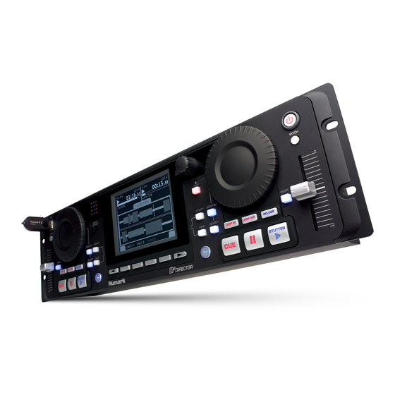
NH00 Top Level System Description rev 0 PG 15 Jan 07 Introduction The NH00 is a rack mount DJ audio player, playing content from USB devices such as flash drives and hard discs. Effects are available that are useful to a DJ: pitch shifting, scratching, looping and beatkeeping. - Page 3 CPU Board This is the main digital 'engine' of the product featuring an ARM CPU running the system software and a DSP providing some additional audio processing. The CPU board has the following main interfaces: 3 x USB host ports. One connects to the port on the front of the unit and two connect to the •...
- Page 4 AKAI 9307 CPU Board Circuit Description rev 0 PG 11 Jan 07 Introduction The 9307 CPU board is used in the NH00 and KA3. It is the main digital 'engine' providing the main system CPU and DSP for audio processing. This document provides a circuit description for this board.
- Page 5 SHEET 1 – CPU This sheet shows the system CPU and associated circuitry. IC4 is a Cirrus EP9307 ARM CPU. The IC runs from a 1.8V core supply (VCCCORE) and a 3.3V I/O supply (VCCIO). IC2 is a 64Mbit flash memory for program and data storage. IC1 and IC3 are SDRAM memory, these run at 100MHz clock speed.
- Page 6 SPI Bus The SPI bus connects the ARM CPU to the Sharc DSP and the PIC microcontroller on the Control board. The SPI bus is used at power up to load software into the Sharc DSP. For this, the ARM CPU is the SPI master and the Sharc DSP is the SPI slave.
-
Page 7: Serial Ports
Serial ports The ARM CPU provides 3 serial ports, of which we make use of 2. TXD0/RXD0 are used for debugging purposes, and this serial port is accessible on the NH00 I/O board. TXD1/RXD1 are not used on the NH00 (on KA3 it is used for the iPod interface). RXD2/TXD2 are not used as a serial port;... -
Page 8: Lcd Backlight Control
LCD backlight control IC10 and associated components provide an adjustable voltage to drive the LCM backlight. The signal BRIGHT is a PWM signal from the ARM CPU. R67/R69/C15 scales and filters this to a DC level, which connects to the adjust pin of the voltage regulator IC10. IC10 will act so as to maintain 1.25V between its output and adjust pin, therefore the output will follow 1.25V above the adjust pin. -
Page 9: Block Diagram
NH00 I/O Board Circuit Description rev 0 PG 12 Jan 07 Introduction This board is used in the NH00 DJ audio player. It includes the audio codec, power supply and power control circuit. Block Diagram I2S Audio to CPU board Audio input 2 ch Audio output 4 ch Audio CODEC... - Page 10 SHEET 1 – CODEC This sheet shows the audio codec, audio input and output circuitry, muting and power supplies for the analogue section. The design features analogue inputs for a record function, though the parts for this are not fitted since the feature was removed from the product.
-
Page 11: Power Control Circuit
SHEET 2 – POWER This sheet shows the system power supply and the power control circuit. The system is powered from a 12V DC power source; this is input on connector J8. D1 is a schottky diode that ensures the system is not damaged should the user accidentally connect a power supply with incorrect polarity. - Page 12 SHEET 3 – Connectors This sheet shows the connection to other boards in the system and also the fader start inputs. The CPU board plugs into 2 50 way headers J11-12. The Control board connects to J16 via a 26 way ribbon cable. The LCD display connects to J15 (data and power), and J14 (backlight).
-
Page 13: Disassembly Procedures
DISASSEMBLY PROCEDURES 1. REMOVAL OF CONTROL PANEL (Fig. 1) (A) TAKE OUT THE 12 PCS SCREW FROM THE CONTROL PANTEL AND FIXED PLATE. Fig.1 2.REMOVAL OF FUNCTIONAL PCB(Fig.2) (A) TAKE OUT THE 2 PCS VR KNOB FROM THE FRONT PANE. (B) TAKE OUT THE DISCONNECT 2 PCS FROM THE LCM AND PC BOARD ASS’Y. - Page 14 DISASSEMBLY PROCEDURES 3. REMOVAL OF TOP COVE. (Fig. 3) (A) TAKE OUT THE 4 PCS SCREW FROM THE CPU PCB ASS’Y. (B) TAKE OUT THE 7 PCS SCREW FROM THE I/O PCB ASS’Y AND TAKE OUT THE 6 PCS SCREW FROM THE REAR COVER .
- Page 15 Q B D L J O H ! E J B H S B N ...
- Page 16 WIRIN G DIAGRAM ~ ~ ~ ~ ~ ~ ~ ~ ~ ~ ~ ~ ~...
- Page 17 ¥ © ¨ ¤ £ § ¥ ¦ £ ¤ ¡ ¢...
- Page 18 NH00MAR01 DESCRIPTION LEVEL AL7-10-0133 USB THUMB DRIVE 128MB BAAR-016 PU STAND BAGL-40A CLIP BAGL-70L CLIP CD47-1 PHONO CORD CN0420000707 4P CONNECTOR (70mm) CN0520002202 5P CONNECTOR (220mm) CN0520002203 5P CONNECTOR (220mm) CN2620003001 26P CONNECTOR (300mm) ERE75 5MM E RING K46-1 CABLE TIE LA62GMN37 DATE LABEL LAC22MAR181...
- Page 19 C1,4,10,13,17~20,22~30,32~38,40,42,45,47,49~60,63,66, CS104K5003X7R CERAMIC 0.1UF (SMD) 71~74,78~80,95,98~116 CS106K0605X5R CERAMIC 10UF (SMD) C96,97 CS470J5003COG CERAMIC 47P (SMD) C16,21,41,46,61,62 DISDBAS40-00 DIODE DIZDBZX84C5V6 DIODE ZENER(5.6V) ICDS1337S IC DS1337S ICDSP21261SKBCZ IC DSP2126SKBZ IC13 ICEP9307-CRZ IC EP9307-CRZ ICK4S281632I IC K4S281632I IC1,3 ICLM1117IMPXADJ IC LM1117IMPXADJ IC10,11 ICLT3021EDH-1.2 IC LT3021EDH-1.2 IC18 ICMAX1940EEE...
- Page 20 CS102J5005NPO CERAMIC 1000P (SMD) C1,2,4,5,22,25,40,43 CS103K5003X7R CERAMIC 0.01UF (SMD) C19,27,32,33,37,44,57~59,63 CS104K5003X7R CERAMIC 0.1UF (SMD) C28,45,61 CS104K5005X7R CERAMIC 0.1UF (SMD) C3,6,20,46,52,53,55,65 CS105K1605X7R CERAMIC 1UF (SMD) C16,34,36,47,49,51,62,64 CS106K1006X5R CERAMIC 10UF(SMD) CS221J5005COG CERAMIC 220P (SMD) C9~12,23,24,41,42 DISDMBRD835LT4G DIODE D1,2 EC10616T ELECT 10UF/16V C26,29,50,54 EC10716T ELECT 100UF/16V C67,68,73...
- Page 21 ICYH95C01 PIC18F65J10 ICPIC18F65J10 FLASH MICN LD-005HLV RED LED LED1~4,9~11,13,16,17,22~24,26,29,30,32,34,38,39,44 LD-005K6CS LED BLUE LED5~8,12,14,18,20,25,28,31,35~37,40~43 LD304W2CB LED WHITE LED15,19,21,27,33 PT0104411 LED HOLDER (LED1~4,6~13) PT0604404 LED HOLDER (LED5,14,15,19~21,25,27,31,33,35) PT111048005 FIXED BASE,LED (LED39,42,43) RS00018J05 RES 0 (SMD) R1,2,4,5,18,19,21,22,33,37,43,44 RS10318J05 RES 10K SMD R23,29,35,38,40 RS10518J05 RES 1M 5% 0805 SMD RS15318J05 RES 15K SMD...
- Page 33 100 ohm 100 ohm MBT4403 100 ohm MBT4401 2SD2114K 2SD2114K 100 ohm Copyright (c) 2006 Akai Digital Ltd. AUDIO POWER SUPPLIES +4VA +4VA COMPANY: NUMARK CFLY- CFLY+ 100uF,16V LP2985-4.0 TITLE: 2 IN 1 VIN VOUT NH00 IO PCB -4VA ON/OFF U3-C...
- Page 34 +5VPERM 5 GP2/T0CKI GP3/MCLR/VPP 2.5V_REF 10.0k 1% LM339 POWER CONTROL MICRO U10-C from CPU +3V3 Copyright (c) 2006 Akai Digital Ltd. +VIN COMPANY: NUMARK From front panel POWER_SW U10-A TITLE: U10-E NH00 IO PCB LM339 0.1uF LM339 LM339 2.5V_REF U10-D...
- Page 35 UART_TX0 0 ohm UART_RX0 BOOT0 0 ohm S6B-PH-KL(LF)(SN) Copyright (c) 2006 Akai Digital Ltd. Use HDX type cable to CPU board COMPANY: NUMARK 1 +VBUS 2 D- USB B 3 D+ TITLE: NH00 IO PCB 0 ohm CONNECTORS 0 ohm...
Need help?
Do you have a question about the D2 DIRECTOR and is the answer not in the manual?
Questions and answers