Advertisement
Quick Links
A
D
E
F
H
Wiring Diagram
Power Supply
115 / 230 VAC
L2 (Neutral)
L1 (Line)
LLS/Compressor
Relay
NC
NO
COM
NC
NO
COM
Setpoints - Basic Menu
Basic Menu
Basic Menu
DEMAND DEFROST
SCHEDULE DEFROST
tS
dtyP
dFit
HAO
LAO
tAd
© Copyright 2019 KE2 Therm Solutions, Inc., Washington, Missouri 63090
This reference should remain on site with the installed KE2 Adaptive Control controller.
KE2 AdaptiveControl
Condensed Quick Start Guide
C
B
I
G
Fan Relay
NC
NO
COM
Defrost Relay
L1
L2
Supply
Voltage
Basic Menu
SCHEDULE DEFROST w. CUSTOM
DEFROST PER DAY
tS
dtyP
dtyP
dFit
dFit
dPd
dPd
dFt
tOd
d1 to d12
HAO
HAO
LAO
LAO
tAd
tAd
(pn 21177)
Parts List
Included in KE2 Adaptive Control kit - pn 21177:
*
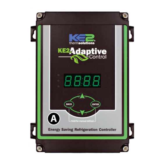
(1) KE2 Adaptive Control 120/208-240 VAC
A
(1) high voltage safety shield
B
(1) 3-pack of colored 15' temp sensors *
C
(6) 90° spade connectors
D
(2) straight spade connectors
E
(5) self-tapping screws
F
(2) 1/2" plastic knockout plug
G
(1) air sensor mount
H
(3) course thread screws
I
J
(1) KE2 Terminal Board
J
(1) EC Motor Relay kit (120V & 240V) w. wire harness
K
(1) Warranty card
L
*
Three temperature sensors are provided. The controller requires a room
temp sensor (T2Air - blue) and a coil temp sensor (T3Coil - yellow) to
function properly. KE2 Therm strongly recommends the third sensor is
used as 2nd coil temp sensor (T4Aux - green).
See Q.1.30 Figure 3 for
wiring of the EC Motor Relay.
BK
EC MOTOR
RELAY
R/W
BL/BK
FAN/S
BL/BK
12 AMP
HEATERS
OR/BK
20 AMP
LL SOLENOID/COMP RELAY
3 AMP
Y/BK
BK/OR
L1
WT/R
L2
OR NEUTRAL
HS
HEATERS
thermsolutions ®
P/N 20996
HEATER LIMIT SWITCH
Description
tS
Temperature Setpoint
Type of Defrost, Air or Electric Air
Defrost Initiation Mode
Number of Defrost Per Day
dFt
Defrost Time
Time of day
Start time of Defrost #1 to #12 0:00, diS
High Alarm Offset
Low Alarm Offset
High & Low Temp Alarm Delay 1 min
(not shown)
Complete Instructions
Please visit:
EVAPORATOR
FANS
http://ke2therm.com/product/
FAN
ke2-adaptive-control-3/
MOTOR
and click the button Link to
Literature.
FAN
— OR —
MOTOR
use this QR code.
FAN
KE2 Adaptive Control
MOTOR
Literature
Min.
Default
-50°F
0°F
ELEc (electric)
dEnd
dEnd (demand)
0
4
0
45 min
0:00
12:00
diS (disabled)
0°
10°if tS < 32°; 3 if ts > 32° 50°
0°
4°
60 min
Q.1.68
June 2019
(not shown)
KE2 Adaptive
Control Videos
Max.
100°F
ELEc
ScHd, FSCH
12, CUS
720 min
23:59
23:59
10°
180 min
Advertisement

Summary of Contents for KE2 AdaptiveControl
- Page 1 This reference should remain on site with the installed KE2 Adaptive Control controller. Q.1.68 KE2 AdaptiveControl June 2019 (pn 21177) Condensed Quick Start Guide Parts List Included in KE2 Adaptive Control kit - pn 21177: (1) KE2 Adaptive Control 120/208-240 VAC (1) high voltage safety shield (1) 3-pack of colored 15’...
- Page 2 Pinch the fins gently together, securing the sensor. This provides thermal ballast, ensuring a complete defrost. KE2 Therm Solutions © Copyright 2019 KE2 Therm Solutions, Inc., Washington, Missouri 63090 12 Chamber Drive . Washington, MO 63090 1-888-337-3358 . www.ke2therm.com...


