Advertisement
Quick Links
Centrale di comando per motori Hercules a 24V
I
Control board for Hercules 24V motors
GB
Centrale de commande pour moteurs Hercules à 24V
F
Steuerzentrale für Hercules-Motoren von 24V
D
Central de mando para motores Hercules a 24V
E
H24
Stagnoli T.G. srl
Via Mantova, trav. I, 105A/B
+39.0309139511
+39.0309139580
info@stagnoli.com
www.stagnoli.com
Advertisement

Subscribe to Our Youtube Channel
Related Manuals for Stagnoli H24

Summary of Contents for Stagnoli H24
- Page 1 Centrale di comando per motori Hercules a 24V Control board for Hercules 24V motors Centrale de commande pour moteurs Hercules à 24V Steuerzentrale für Hercules-Motoren von 24V Central de mando para motores Hercules a 24V Stagnoli T.G. srl Via Mantova, trav. I, 105A/B +39.0309139511 +39.0309139580 info@stagnoli.com...
- Page 2 The Stagnoli H24 is the control board that has been studied for 24V Hercules automations. Made using only prime quality materials, it has been designed for low absorption at rest allowing a low consumption of electricity. Particular attention has been paid to professionals in the sector making it easier to programme the control board by using a multi-language display.
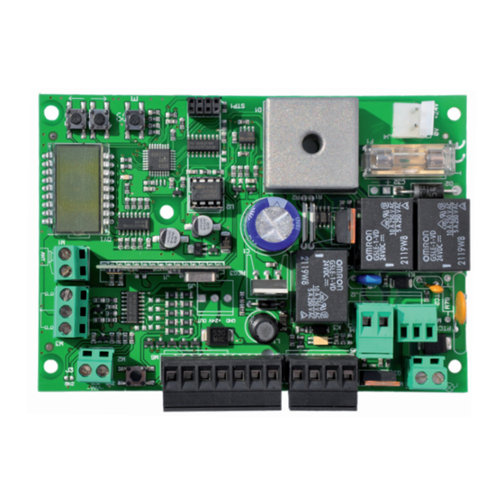
- Page 3 Jump resistive rib Limit stop terminal Radio aerial terminal Display Rib entry terminal Setting keys Input/Control connectors Receiver module System memory (removable) 24V Terminal/fl asher Flasher relay Mosfet motor Mosfet open gate detector exit Motor connector Opening relay Rapid fuse 2,5A (card and accessories protection) Open gate detector terminal (SCA) Encoder connector 24V current card terminal...
- Page 4 LINE common start start photocells in closing stop ph1 ph2 ph3 ph4 photocells in pedestrian 1,25A opening and in closing common accessory exit 0 230 black fl asher white TRASFORMATOR green 24 0 brown open gate detector (SCA) The current feed line (230V L,N, ) towards the automated device must be protected by a magnetometric switch or by a pair of 5A fuses.
- Page 5 Operating procedure at the fi rst start up •Undertake the electric wiring for the plant and check when the card is switched off. display •Unblock the gate and check its movement (the rack must not be supported by the motor pinion). The stroke of the gate must not have any areas of stiffness during movement, it must be smooth.
- Page 6 • = rolling code receiver indicator • = gate opening direction indicator • = registered transmitters r|-00 add transmitter adjustement function ttca aped add transmitter • = me- rlap morisation of radio con- trols rlch • = memorisation of the radio control key on the fm1a fi...
- Page 7 • = instant power absorbed by the motor • = encoder operation indicator 00 - delete language setup default parameter italiano read code erase 1 transmitter english erase memory transmi t ters ttca • = automatic closing time aped • = pedestrian opening rlap •...
- Page 8 (slowed stroke in opening)= the control board slows down the stroke of the motor in the end part of its opening phase. The default stroke set by Stagnoli is 20 cm and it can be regulated from 0 to 70 cm.
- Page 9 WARNING: the setting of these two parameters can infl uence the level of safety of the system itself. Stagnoli advises setting this parameter with a safety margin that is at least +10 compared with the maximum current consumed by the motor respectively in the opening and closing phases.
- Page 10 light will activate for two seconds before the opening or closing phase begins. pl=0 function not enabled. pl=1 function enabled. • (energy saving)= keeps the photocells off while the system is not active per- mitting energy saving. The photocells therefore remain active only while the gate is in movement.
- Page 11 fi xed code. WARNING: The receiver can memorise rolling codes type HCS300 STAGNOLI with billions of combinations or fi xed codes type HT53200 with 13 bits or the fi xed part of a rolling code (28 bit SN).
- Page 12 Before proceeding with this operation, ensure that the gate has been installed correctly and fi rmly and that the function of the control board has been activated (Stagnoli supplies the control board with this function already activated). setup When the wording appears on the display, press ENTER.
- Page 13 Diagnostics screens The control board can recognise problems or alarms that can occur in the system therefore it can signal some messages on the main display to allow the problem to be identifi ed: 1 rf • = activation of the START command on the fi rst radio frequency channel. 2 rf •...
-
Page 14: Frequently Asked Questions
1024 code combinations that do not change with each transmission. Can the control board run the operation of the motor with emergency batteries? Yes. To use emergency batteries use the kit supplied by Stagnoli. The control board does not recognise the transmitter. Why? Check that you are using the same type of control board and transmitter. - Page 15 Notes...
- Page 16 LIMIT STOP ANTENNA SAFETY RIB COMMANDS COMMON START STOP PEDESTRIAN OPENING COMMON +24V -24V SUPPLY FLASHER COURTESY LIGHT OPEN GATE DE- TECTOR LIGHT MOTOR...
- Page 17 CLOSING CLOSING PHOTOCELLS PHOTOCELLS OPENING AND CLOSING PHOTOCELLS COMMON +24V -24V OPENING PHOTOCELLS BATTERIES BATTERY-CHARGER BOARD WARNING: If a battery charger is used, the control board is supplied by the C24 charger board, linked to a trasnsformator. For the details of the connection, see the C24 instructions.
Need help?
Do you have a question about the H24 and is the answer not in the manual?
Questions and answers