Table of Contents
Advertisement
Quick Links
Advertisement
Table of Contents

Summary of Contents for Leach MINI REAR
- Page 1 OADER ’ PERATOR ANUAL...
- Page 3 OADER ’ PERATOR S MANUAL...
- Page 4 Liability Labrie Enviroquip Group assumes no liability for any incidental, consequential, or other liability that might result from the use of the information contained in this document. All risks and damages, incidental or otherwise, arising from the use or misuse of the information contained herein are entirely the responsibility of the user.
-
Page 7: Table Of Contents
Table of Contents Liability ..................ii Table of Contents ................. v Introduction ................1 Introducing the M ............................... 1 OADER Product Overview ..................................2 Available Options ..................................6 Standard Limited Product Warranty ............................7 Office Addresses and Phone Numbers ............................. 9 In the U.S. - Page 8 vi Table of Contents Switch (optional) ..........................58 PERATING OSITION Driver Enable Button (optional) ............................58 Rotary Selector Switch (optional) ............................59 Indicators ......................................59 Light ................................. 59 AILGATE Light ................................ 60 CCESS Outside Controls .................................... 61 Push-Buttons ............................61 NGINE PEED Push-Buttons (Units w/ an Electrically Powered Chassis) ............
-
Page 9: Introduction
Introduction The purpose of this manual is to introduce operators to the operational procedures of the M garbage truck. Through the following pages OADER you will find a lot of useful material about the truck itself but also about the safety precautions that need to be taken during your day-to-day normal tasks. -
Page 10: Product Overview
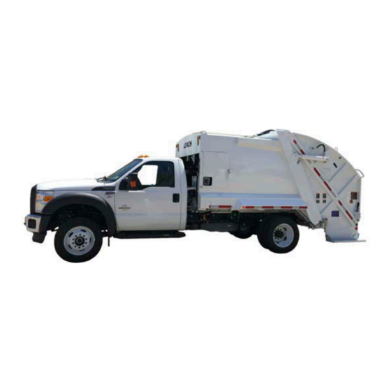
2 Introduction However, despite of their small waste body, M units have a large hopper which is OADER wide enough to handle commercial containers. A number of options are available for the M (see later in this Section). OADER Product Overview The M is a small, reliable and user-friendly collection truck. - Page 11 Introduction 3 Figure 1-3 Tailgate (left), packer (right) Figure 1-4 Hopper (left), carrier panel (right) Figure 1-5 Pushout panel...
- Page 12 4 Introduction In the cab, you will find most light indicators and control switches, such as the E NGINE PEED switches, on the optional console (see Figure 1-7) or on the dashboard YDRAULIC (see Figure 1-6). : In-cab switches on M units with an electrically powered chassis are different OADER from those on units with a fuel/CNG-powered chassis.
- Page 13 Introduction 5 Operating controls for the packer panel, carrier panel, container handling system (optional), and tipper (optional) are located on the right side of the tailgate. Figure 1-9 Operating controls ARRIER controls ACKER control IPPER Operating controls for the pushout panel and the tailgate are located near the front streetside corner of the body.
-
Page 14: Available Options
6 Introduction Figure 1-11 buttons (H buttons on electrically powered units) PEED YDRAULIC NABLE Available Options Tippers Winch and reeving cylinder CNG systems (behind-the-cab and roof-mounted) Work lights and strobes Push bar Hydraulic auto-latch system ... -
Page 15: Standard Limited Product Warranty
Introduction 7 Standard Limited Product Warranty Subject to the other provisions hereof, LABRIE ENVIROQUIP GROUP, hereinafter called “Labrie” warrants that all new Labrie products (the “Product”) shall be free of defects in material and workmanship under normal use and service for a period of ONE (1) YEAR after delivery to the first registered customer/end-user. - Page 16 8 Introduction Because the Product is engineered to work only with genuine Labrie parts and components, this warranty shall be void and of no effect if i) the Product is modified other than by Labrie or by an authorized Labrie distributor or other than in accordance with a specific authorization and instructions from Labrie or from an authorized Labrie distributor or ii) if parts and components of any other manufacturer are used as substitutes for genuine Labrie parts and components.
-
Page 17: Office Addresses And Phone Numbers
Introduction 9 Office Addresses and Phone Numbers In the U.S. Address: 1198 Shattuck Industrial Blvd. LaFayette, GA 30728 Toll Free: 1-800-231-2771 Telephone: 1-706-591-8764 General Fax: 1-706-639-9275 Oshkosh General Fax: 1-706-591-8766 Parts and warranty: During business hours, 8:00 AM to 6:00 PM Eastern Standard Time Technical Support Service: Available 24 hours In Canada Address:... - Page 18 10 Introduction...
-
Page 19: Safety
Safety This manual contains safety information that could MPORTANT prevent accidents. Read and thoroughly understand it before using the vehicle. To us all at Labrie Enviroquip Group, the safety of vehicle operators is one area of great importance. Thus, this vehicle was built in accordance with the American National Standards Institute ( ANSI standard for Mobile Refuse Collection and... -
Page 20: Conventions
12 Safety Conventions Danger! Indicates a hazardous situation which, if not avoided, will result in serious injury or death. Warning! Indicates a hazardous situation which, if not avoided, could result in serious injury or death. Caution! Indicates a hazardous situation which, if not avoided, may result in minor or moderate injury or property/product damage. -
Page 21: Responsibilities
Safety 13 Responsibilities Safety is everybody’s responsibility. Both employer and employee must play their part to ensure the safety of the operator, the vehicle, and its immediate surroundings. Employer Responsibilities It is the responsibility of the employer: To ensure that employees are qualified for operating the vehicle and its equipment, and that they all take safety measures before using them. -
Page 22: Things To Do
14 Safety Things to Do Inspect the body and all systems at the beginning of each day. Make sure that the area is clear of any people or possible obstructions. Be extremely cautious in areas where small children may be present. MPORTANT ... -
Page 23: General Operation
Safety 15 Never operate machinery while under the influence of alcohol, narcotics or other mood altering substances. Workers who operate machinery while under the influence are a hazard to themselves others. Perform a pre-operation “walk around” inspection of the truck chassis in accordance with the chassis manufacturer’s guidelines. - Page 24 16 Safety Move the vehicle as slowly as possible without stalling when traveling in reverse. Always make sure the area behind the unit is clear before traveling in reverse. Do not travel in reverse for distances greater than those dictated by local ordinances.
- Page 25 Always set the vehicle parking brake before attaching or lifting a container (units with a container handling system). Never lift a container which is non-compatible with the Leach container attachment (units with a container handling system). Never lift a container without first latching both container latch arms (units with a container handling system).
-
Page 26: Hydraulics
18 Safety Do not attach the hook to any open loop lift attachment feature with the safety latch closed. The hook must be secured to a closed loop lifting feature. Do not remove the hook safety latch. (Units with a container handling system.) ... -
Page 27: Housekeeping
Safety 19 Never load ashes or other materials which might be smoldering. These materials could ignite refuse in the waste body. vehicles are equipped with a 5-lb fire extinguisher, which is located inside OADER the cab. A 20-lb fire extinguisher may also be installed as an option. Each fire extinguisher must be checked regularly by qualified personnel. -
Page 28: Safety And Informative Decals
20 Safety Figure 2-2 NPT plug (left), optional drain (right) Safety and Informative Decals Pay careful attention to all safety, warning and informative decals while working in and around the . Keep your decals clean and in good condition at all times. For replacement OADER decals, please call LabriePlus. - Page 29 Safety 21 104029 104030 - Spanish 104589 104028 - French 84286 - English/Spanish 84285 - English/French 104035 104036 - Spanish 104569 104034 - French 84294 - English/Spanish 84293 - English/French 104041 104042 - Spanish 84032 104040 - French 84031 - English/French 104539 - English/French/Spanish...
- Page 30 22 Safety 104566 Optional 104567 - Spanish 104565 - French 104531 84488 104532 - Spanish 104530 - French 207583 Optional - Units w/ electrically powered chassis only 104068 84166 - English/Spanish 84165 - English/French...
- Page 31 Safety 23 170414 Optional 32272 47520 47521 - French 47256 84419 - Spanish 159761 - French Optional 32411 Optional 121344 159828 Optional...
- Page 32 24 Safety 97832 84447 - Spanish Optional 159805 159807 - Spanish Optional 159759 - French 159806 - French 159852 58704 - French Optional...
- Page 33 Safety 25 UNLOADING INSTRUCTIONS FOR PUSHOUT SYSTEM TO OPEN TAILGATE EJECTION SPEED UP 1. Activate the hydraulic pump. (Cab controls not shown). BUTTON 2. Turn solenoid to "ON" position (Cab controls not shown). TAILGATE TAILGATE LATCH 3. Always set brake before leaving cab. UNLOCK 4.
- Page 34 26 Safety 84388 84389 - French This vehicle conforms to all ANSI Z 245.1 safety requirements effective on the manufacturing date. REV. C LABRIE 104044 104044 104045 - Spanish 104043 - French...
-
Page 35: Decals On Tailgate
Safety 27 Decals on Tailgate 32411 Optional 104525 Optional 104083 104526 - Spanish 104084 - Spanish 104524 - French 104082 - French 104032 104035 104033 - Spanish 104036 - Spanish 104031 - French 104034 - French 104054 104048 Optional 104049 - Spanish 104055 - Spanish 104047 - French 104053 - French... - Page 36 28 Safety 104534 104535 - Spanish 104186 104533 - French 104187 - Spanish 104185 - French 104098 104099 - Spanish 104097 - French 104519 104080 84284 - English/Spanish 104081 - Spanish 84283 - English/French 104079 - French 104671 104672 - French...
- Page 37 Safety 29 104089 104095 84290 - English/Spanish 104090 - Spanish 84289 - English/French 104088 - French 104507 47266 104508 - Spanish 120973 - English/Spanish 104506 - French 79835 - English/French 104516 104589 84292 - English/Spanish 84286 - English/Spanish 84291 - English/French 84285 - English/French...
- Page 38 30 Safety 104513 104051 84282 - English/Spanish 104052 - Spanish 84281 - English/French 104050 - French 84032 104510 84031 - English/French 84280 - English/Spanish 104539 - English/French/Spanish 84279 - English/French 104641 170414 Optional THIS VEHICLE IS POWERED BY NATURAL GAS 32414 Optional 84418 - Spanish...
-
Page 39: Decals Inside Cab
Safety 31 104149 207583 104150 - Spanish Optional - Units w/ electrically powered chassis only 104148 - French Decals Inside Cab 204541 204522 204517 - English/French 195248 - English/French 204536 176994 Optional 204512 - English/French... - Page 40 32 Safety 84328 84329 84330 84331 104666 - French 104665 - French 84332 84333 84334 84335 104667 - French 173541 - French 104668 - French 104669 - French 159765 84032 104670 - French 84031 - English/French 104539 - English/French/Spanish...
- Page 41 Safety 33 104038 84164 - English/Spanish 84163 - English/French 104001 84189 104002 - Spanish 84188 - English/French 104000 - French DANGER - Do not transport containers with the lifting devices. - Transporting a container could result in personal injury or property damage.
- Page 42 34 Safety 207152 104089 104090 - Spanish 104088 - French 47420 104074 84420 - Spanish 104075 - Spanish 104073 - French 159755 - French Optional 104166 104167 - Spanish 170414 Optional 104165 - French...
- Page 43 Safety 35 204532 204502 - English/French 204543 204519 - English/French 204530 204510 - English/French...
-
Page 44: Safety Features
36 Safety Safety Features Back Up Alarm The back up alarm sounds when the transmission is put into reverse or when the tailgate opens. Tailgate Safety Props The tailgate safety props are used to support and keep the tailgate open during inspection or maintenance procedures. - Page 45 Safety 37 Turn ON the pump. Danger! Prior to raising the tailgate, make sure that no one is standing behind the vehicle and that the body is empty. Using the T lever (see Figure 2-4) raise the tailgate by about 3 feet (enough to swivel AILGATE both safety props towards the body).
- Page 46 38 Safety Lower the tailgate until both safety props lean against the body base using the T lever. AILGATE Figure 2-6 Props set against body base Putting the Tailgate Safety Props Back in Place (for units w/ a fuel/CNG-powered chassis) : For units with an electrically powered chassis, go to page 42.
- Page 47 Safety 39 Figure 2-8 Prop securely latched Secure each prop using the provided latch. MPORTANT Using the T lever (see Figure 2-4), fully close the tailgate. AILGATE The T light indicator (see Figure 2-9) should turn off. AILGATE Figure 2-9 light indicator (on dashboard, left, on optional console, right) AILGATE Put the tailgate clamps back in place (see Figure 2-3).
- Page 48 40 Safety Setting the Tailgate Safety Props (for units w/ an electrically powered chassis) : For units with a fuel/CNG-powered chassis, go to page 36. To set the tailgate safety props: Make sure that the body is empty. Remove the tailgate clamps. To do so: Loosen the clamp.
- Page 49 Safety 41 Press the H push-button on the front left-hand side corner of the body. YDRAULIC NABLE Once he presses this push-button, the operator will have 60 seconds to activate either the tailgate up/down function or the pushout in/out function. The operator must activate either function within that time period.
- Page 50 42 Safety Figure 2-14 Props in stored position Lower the tailgate until both safety props lean against the body base using the T lever. AILGATE Be sure to press the H push-button (see Figure 2-12) first and then use the YDRAULIC NABLE lever.
- Page 51 Safety 43 Swivel back each safety prop and latch it into place under the tailgate (see Figure 2-7 and Figure 2-8). Danger! Stand clear of the tailgate path while putting the safety props back into their stored position. Figure 2-16 Putting back props into stored position Figure 2-17 Prop securely latched...
-
Page 52: Camera System (Optional)
44 Safety The T light indicator (see Figure 2-18) should turn off. AILGATE Figure 2-18 light indicator on dashboard AILGATE Put the tailgate clamps back in place (see Figure 2-10). To do so: Swivel back the clamp against the body. 8 a. -
Page 53: Mol Safety Operation System (Optional)
Safety 45 MOL Safety Operation System (optional) Labrie option “Packer Protection – 2nd-hand enable buttons and guard (MOL 2004)” is mandatory in certain locations. However, it can also be installed as an additional safety system if requested. This option is composed of four buttons: ... -
Page 54: Tailgate Open Proximity Switch Test
46 Safety Figure 2-21 Mid-Body enable button (left), rotary switch (right) Proximity Switch Test AILGATE The T Proximity Switch Test should be part of your daily inspection. Successful AILGATE completion of this test ensures that your unit is safe to operate. If this test fails, do not operate your unit until the appropriate adjustment or service has been completed. -
Page 55: Access Door Open Limit Switch Test
Safety 47 The H push-button, only on units w/ an electrically powered chassis, allows YDRAULIC NABLE the operator to activate a specific hydraulic function when needed. Once the operator presses this push-button, he will have 60 seconds to activate either the tailgate up/down function or the pushout in/out function. - Page 56 48 Safety Figure 2-23 Access door Ensure that the A light indicator on the dashboard or on the optional console CCESS is lit. Figure 2-24 light indicator (on dashboard, left, on optional console, right) CCESS Figure 2-25 light indicator (optional switch/indicator layout) CCESS...
-
Page 57: Locking Out And Tagging Out The Vehicle
Safety 49 Verify that the hydraulic system has been rendered inoperative by activating one of the control levers, such as the E lever (see Figure 2-4). JECTION The operator of a unit w/ an electrically powered chassis must first press the H YDRAULIC NABLE push-button (see Figure 2-12) before activating either the E... - Page 58 50 Safety Figure 2-27 Master switch (optional) Figure 2-28 Master switch (on units w/ an electrically powered chassis) Chock all wheels. Put an “O ” tag on the driver’s wheel and on the front windshield. ERVICE Secure an open tailgate with the provided safety props to prevent movement due to gravity. Drain all air tanks.
-
Page 59: Shutting Down The Vehicle
Safety 51 Shutting Down the Vehicle If the vehicle has to be stored for an extended period of time, follow the chassis manufacturer’s shutdown and maintenance requirements. Also: Park the vehicle on a hard level surface and apply the parking brake (see Figure 2-26). Make sure that all moving parts are in their home position (tailgate, packer, etc.). - Page 60 52 Safety : The hydraulic tank model may vary according to the options installed on the vehicle. Warning! Failure to fully open the shut-off valve will cause immediate damage to the pump, even if the pump is turned off. Start the engine. Wait for the air pressure to build up to at least 70 psi.
-
Page 61: Controls, Indicators And Processes
Controls, Indicators and Processes The M has a series of controls and OADER indicators that allow easier operation of the different functions that come with the vehicle. The indicators are mainly located on the dashboard or on the optional console, while the operating controls are mostly located on the right side of the tailgate and some on the front left side corner of the body near the access door. -
Page 62: Hydraulic Pump O N /Off Switch
54 Controls, Indicators and Processes Switch YDRAULIC This switch engages and disengages the hydraulic pump that powers all body and tailgate functions. Turn ON this switch to activate the hydraulic pump. Turn OFF this switch to deactivate the hydraulic pump. Figure 3-2 switch (on dashboard, left, on optional console, right) YDRAULIC... -
Page 63: Engine Speed -U P Switch (Units W/ Fuel/Cng-Powered Chassis Only)
Controls, Indicators and Processes 55 Switch (Units w/ Fuel/CNG-Powered Chassis NGINE PEED Only) This switch energizes the engine speed-up system. It is located either on the in-cab console or on the dashboard (see Figure 3-4). The speed-up feature is used to rev up the pump providing additional flow to the hydraulic features and reducing cycle times. -
Page 64: Work Light Switch (Optional)
56 Controls, Indicators and Processes Switch (optional) IGHT This switch (see Figure 3-6 and Figure 3-7) turns on/off the work light if installed on your M OADER Pushing the top of the switch will turn the work light on. ... -
Page 65: Hopper Light Switch (Optional)
Controls, Indicators and Processes 57 Figure 3-8 switch (on dashboard, left, on optional console, right) TROBE IGHT Figure 3-9 switch (optional switch/indicator layout) TROBE LIGHT Switch (optional) OPPER IGHT This switch (see Figure 3-10) turns on/off the hopper light if installed on your M OADER ... -
Page 66: Operating Position Switch (Optional)
58 Controls, Indicators and Processes Switch (optional) PERATING OSITION : This switch is found only in modified cabs. Use this switch to change your driving position from the right side to the left side of the cab or vice- versa. ... -
Page 67: Rotary Selector Switch (Optional)
Controls, Indicators and Processes 59 Rotary Selector Switch (optional) This selector switch (see Figure 3-13) is used to select the number of enable buttons that need to be pressed and held simultaneously to activate the packer in the protected zone . -
Page 68: Access Door Open Light
60 Controls, Indicators and Processes Figure 3-14 light (on dashboard, left, on optional console, right) AILGATE Figure 3-15 light (optional switch/indicator layout) AILGATE Light CCESS This light indicator, located either on the dashboard or on the optional console, is used to warn the operator that the access door is open or not properly closed. -
Page 69: Outside Controls
Controls, Indicators and Processes 61 Figure 3-17 light (optional switch/indicator layout) CCESS : No hydraulic function is possible when the access door is not closed. Outside Controls Push-Buttons NGINE PEED When depressed, these push-buttons will cause the engine to speed up and provide additional flow to the hydraulic system. - Page 70 62 Controls, Indicators and Processes Figure 3-19 push-button on tailgate right side NGINE PEED : There are no E push-buttons nor in-cab S switch on a unit w/ an NGINE PEED PEED electrically operated chassis because the pump is mounted to an ePTO and is therefore independent of the propelling engine(s).
-
Page 71: Hydraulic Enable Push-Buttons (Units W/ An Electrically Powered Chassis)
Controls, Indicators and Processes 63 The M is equipped with 2 push-buttons: one is located at the OADER HYDRAULIC ENABLE rear of the truck near the P control levers, the other on the left-hand side corner of ACKER ARRIER the body near the P control levers. -
Page 72: Tailgate Clamps
64 Controls, Indicators and Processes Tailgate Clamps Tailgate clamps are located on each side of the tailgate at the bottom where the tailgate rests against the body (see Figure 3-21). They are used to secure the tailgate to the body during operation. These clamps must be manually loosened and swung away from the body before raising the tailgate. -
Page 73: Packer And Carrier Panel Levers
Controls, Indicators and Processes 65 and C Levers ACKER ARRIER ANEL Lever ACKER ANEL The P control lever is located on the right side of the tailgate (see Figure 3-23). It is ACKER ANEL used by the operator to move the packer panel into position either open or closed during the compaction cycle. -
Page 74: Container Handling Control Levers (Optional)
66 Controls, Indicators and Processes Levers (optional) ONTAINER ANDLING ONTROL These control levers are provided when container handling attachments (drum winch, reeving cylinder or container push bar) are added to the unit. They are used to raise and lower the container causing the refuse to be deposited into the hopper for compaction. -
Page 75: Tailgate And Mid-Body Enable Buttons (Optional)
Controls, Indicators and Processes 67 Figure 3-25 lever on tailgate right side (1), on tailgate left side (2) IPPER Tailgate and Mid-Body Enable Buttons (optional) These optional buttons (see Figure 3-26) are part of the MOL Safety Operation System which is mandatory in certain locations (see MOL Safety Operation System (optional) on page 45 for more details on this system). -
Page 76: Container Handling Process
68 Controls, Indicators and Processes Container Handling Process If your unit is equipped with a container handling system, here are the 3 basic operation steps involved in this process: Attaching The first step in container handling is to attach the container to the rear loader by securing it with the latch arms of the container attachment. -
Page 77: Releasing
Controls, Indicators and Processes 69 Releasing When the container is empty, it is lowered to the ground, the latch arms are released and the truck is moved forward. round, rward. Releasing container Waste Handling Process The main purpose of the M is to safely and efficiently load, pack, transport and OADER... - Page 78 70 Controls, Indicators and Processes Carrier and packer panels move over load Next, the carrier and packer panels automatically stop at the “interrupted cycle” position. CARRIER PANEL “Interrupted cycle” PACKER PANEL The operator again activates the packing cycle. The carrier and packer panels move forward and sweep the refuse from the hopper up into the body and pack it against the pushout panel.
-
Page 79: Unloading
Controls, Indicators and Processes 71 CARRIER PANEL PUSHOUT PANEL Pushout panel moves forward PACKER PANEL Unloading At the dumpsite, the unit is unloaded in two easy steps: 1. The tailgate is raised by the operator. 2. The pushout panel is moved to the rear of the body, pushing out the load. Tailgate raised TAILGATE After unloading, the tailgate is lowered and “latched”... - Page 80 72 Controls, Indicators and Processes...
-
Page 81: Operating The Mini Rear Loader
Operating the M OADER The different methods, procedures and necessary actions to operate the M OADER presented in this section. Warning! Always read and understand the Operator’s Manual before operating the unit. Before operating the M , the operator OADER must be completely familiar with all safety procedures, and the location, operation and functions of all controls and indicators related to the operation of the... - Page 82 74 Operating the M OADER Inspect the attaching hardware. Make sure everything is tight and that there are no broken or excessively worn parts. Check capscrews and fasteners for looseness, visible welds for cracks and control levers for each movement. ...
- Page 83 Operating the M OADER With the engine running, the hydraulic pump engaged, the in-cab S switch ON, the PEED transmission in neutral and the brakes applied, depress the S push-button on the front PEED left side corner of the body (see left picture in Figure 3-18). You should hear the engine speed-up. : On units with an electrically powered chassis, there are no in-cab/body/tailgate S PEED switches or push-buttons.
- Page 84 76 Operating the M OADER Move both the P lever and the C lever outward and let go. ACKER ANEL ARRIER ANEL • Observe the carrier and packer panel movement; it should be smooth. The panels should stop automatically at the “home” position. : On some trucks, the packer and carrier levers are shifted downward instead of outward.
-
Page 85: Walk Around Inspection Checklist
Operating the M OADER Walk Around Inspection Checklist Decals in place and readable. Look for any fluid leaks. Mounting hardware tight and in place. Tailgate clamps closed and tightened. Hydraulic fluid reservoir at correct level. ... -
Page 86: Inspection Sheet
78 Operating the M OADER Inspection Sheet The following is an example of an inspection sheet. The operator MUST follow the inspection sheet provided by his employer. If the employer does not have any, ask for his permission before using this example sheet. -
Page 87: Operating Instructions
Operating the M OADER Operating Instructions Starting Up 1. Inspect and start the truck as described in the pre-operational “walk-around” inspection. 2. Wait for the air pressure to reach at least 70 psi. 3. Engage the H switch (to start the hydraulic pump) [see H YDRAULIC YDRAULIC Switch on page 54]. - Page 88 80 Operating the M OADER button/ lever Figure 4-2 NGINE SPEED PUSHOUT JECTION lever PUSHOUT NGINE PEED button button Figure 4-3 YDRAULIC ENABLE...
-
Page 89: Loading The Hopper
Operating the M OADER Loading the Hopper There are only a few but important points to remember during loading of refuse: Load the hopper evenly on both sides. Load heavy objects in the center of the hopper. Do not load refuse higher than the loading edge. Warning! Always follow proper loading procedures. -
Page 90: Using The Optional Winch Or Container Lifting Cylinder
82 Operating the M OADER Attached Warning! Lifting a container without both latch arms properly secured can allow the container to swing away from the unit and cause severe injury or death. : If the container is equipped with wheels, it should be rolled into position only after the vehicle parking brake has been set. - Page 91 Operating the M OADER The Hook: 1. Throat Opening 2. Back 3. Heel 4. Hook Safety Latch 5. Tip 6. Base Hooks must be used in a proper manner. Proper use of a lifting hook not only includes placing the MPORTANT load in the base of the hook, but also includes ensuring that the hook is lifting on the proper area of the attachment point.
- Page 92 84 Operating the M OADER CONTAINER HANDLING CONTROL LEVERS : The above illustration is used for reference only and may differ from actual appearance. The container should be raised up to the stop bar to fully download the trash material (see next illustration).
-
Page 93: Using The Optional Container Push Bar (Cpb)
Operating the M OADER push-button (left), H push-button (right) Figure 4-4 NGINE PEED YDRAULIC NABLE On units with a roof-mounted container lifting cylinder, the speed of the device is limited during both the up and down movements. This speed reduction is for safety considerations. When the hopper is full, lower the container to the ground, assure all persons are standing clear and then engage the packer mechanism (see Collecting Refuse with a Cart Tipper on page 87). - Page 94 86 Operating the M OADER : On units w/ an electrically powered chassis, operators need to press the H YDRAULIC NABLE push-button to activate this feature. CONTAINER CONTROL LEVER : The illustration above is used for reference only and may differ from actual appearance. Do not overfill the hopper.
-
Page 95: Collecting Refuse With A Cart Tipper
Operating the M OADER Collecting Refuse with a Cart Tipper : This section only applies to units equipped with a cart tipper. To collect refuse using the cart tipper: Roll the cart to the tipper in a way that it can be picked up. Push the cart tipper lever (see Figure 4-6) until the tipper is in horizontal position. -
Page 96: Packing The Load
88 Operating the M OADER control lever Figure 4-6 IPPER Once the cart is empty, bring the cart down by pulling the T lever. IPPER : On some units, tipper controls are inverted upon request by the customer. Put the cart back to its original location and fully close the tipper. Packing the Load : The packing cycle can be stopped at any time by moving both the P lever and the... - Page 97 Operating the M OADER The packer panel will open and the P lever will automatically shift back to neutral. The ACKER carrier panel will then move down to above the loading edge, stop in the “interrupted cycle” position and the C lever will automatically shift back to neutral.
-
Page 98: Pushout Panel Operation During Packing
90 Operating the M OADER Tailgate enable button Figure 4-8 Pushout Panel Operation During Packing The M telescopic pushout cylinder will normally move toward the front of the body OADER automatically. When the resistance circuit is adjusted to produce maximum load density, it may become necessary to manually retract the telescopic pushout cylinder in order to allow the compacted refuse to move forward in the body. -
Page 99: Releasing The Container
Operating the M OADER Releasing the Container Once the container is empty, it should be lowered to the ground, the latch arms released and the cable disconnected. Unloading at Dumpsite Caution! Do not unload uphill or against a pile of refuse. 1. -
Page 100: Ejecting The Load
92 Operating the M OADER push-button (left), T lever (right) Figure 4-10 NGINE PEED AILGATE Warning! The T light and backup lights should illuminate. The backup alarm should also AILGATE sound. Ejecting the Load To eject the load: Depress and hold the E button, push the P lever rearward and hold it NGINE... -
Page 101: Lowering The Tailgate
Operating the M OADER button (left), P lever (right) Figure 4-11 NGINE PEED USHOUT Caution! After unloading, the pushout cylinder should be kept extended. If the unit is going to travel over one mile empty, completely retract the cylinder. When packing is about to resume, extend the cylinder and start packing. -
Page 102: Shutting Down The Truck
94 Operating the M OADER lever Figure 4-12 AILGATE Shutting Down the Truck To shut down the truck: Place the packer and carrier panels in the “home” position (packer open and carrier up). Put all controls in neutral. Set parking brake. Turn OFF the E switch. - Page 103 S E R V I C E P A R T S Our office in the U.S. Our office in Canada 1198 Shattuck Industrial Blvd. 455 1st Avenue LaFayette, GA 30728 Levis, QC G6W 5M6 Toll Free: 1-800-231-2771 Toll Free: 1-877-452-2743 Telephone: 1-706-591-8764 Customer Service Phone: 1-877-452-2743 General Fax: 1-706-639-9275...
Need help?
Do you have a question about the MINI REAR and is the answer not in the manual?
Questions and answers