
Related Manuals for EDS SPM-010

Summary of Contents for EDS SPM-010
- Page 1 SPM-010 Sump Pump Monitor and Control Unit EDSPN: 2052102004 Electronic Design Service SPM-010 Sump Pump Monitor/Control Unit User Guide © Copyright 2022 Electronic Design Service, LLC All Rights Reserved Page 1...
-
Page 2: Revision History
SPM-010 Sump Pump Monitor and Control Unit EDSPN: 2052102004 Revision History The Table below displays the revision history for the chapters in this User Guide Date Version Change Made April 24, Original release 2022 Contact Us For the most up-to-date information about the Electronic Design Service products, go to the Electronic Design Service website at www.eldesignservice.com. -
Page 3: Table Of Contents
Figure 2 Inside Home Application only ....................... 9 Figure 3 Inside and Outside Home Application ..................10 Figure 4 Connection Diagrams SPM-010 v4 (top) and SPM-010 v5 (bottom) ........... 11 © Copyright 2022 Electronic Design Service, LLC All Rights Reserved... - Page 4 Figure 5 WS-010 Sensor (without Sensor Installation Pipe (SIP)) and SPM-010 Installation diagram for Monitoring Operation Mode ........................13 Figure 6 WS-010 Sensor with SIP and SPM-010 Installation Diagram for Monitoring Operation Mode ... 14 Figure 7 Resistive sensor and SPM-010 Installation Diagram for Monitoring Operation ......16 Figure 8 Resistive sensor, SPM-010 and SSR-CU Installation Diagram for Monitoring and Control Operation Mode ............................
-
Page 5: About Spm-010 Sump Pump Monitor/Control Unit
Effective pump control Ability to operate in case of power outage SPM-010 unit monitors critical parameters of the home such as sump pump power loss, sump “True” Water level (with adjustable alarm level), air temperature device operational status and device battery charging status. - Page 6 SPM-010 Sump Pump Monitor and Control Unit EDSPN: 2052102004 Figure 1 Normal Operation Screen Example © Copyright 2022 Electronic Design Service, LLC All Rights Reserved Page 6...
-
Page 7: Specifications
FCC Compliance: FCC CFR47, Part 15 and ARIB STD-T-66 Pump Control Interface: two pins LED control with 3mA current maximum (Solid State Relay Control) SPM-010 Application SW: iOS 14.5 or newer version devices © Copyright 2022 Electronic Design Service, LLC All Rights Reserved... -
Page 8: Inside Box
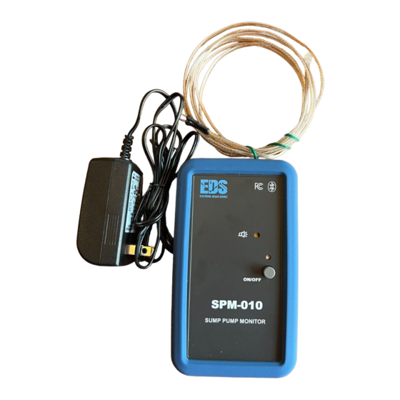
Inside Box 1. SPM-010 device 2. WS-010 water level sensor 3. AA size Dummy Cell (needs to be installed in SPM-010 in empty battery slot) 4. 120VAC / +5VDC Power adapter © Copyright 2022 Electronic Design Service, LLC All Rights Reserved... -
Page 9: Components And Applications
SPM-010 Sump Pump Monitor and Control Unit EDSPN: 2052102004 Components and Applications House Bluetooth Zone Real Time Parameters: SUMP PUMP AREA - True Water Level - Sump Pump Power and Operation Statuses Pump Control Wire Level Sensor - Air Temperature... - Page 10 SPM-010 Sump Pump Monitor and Control Unit EDSPN: 2052102004 iPhone/iPAD House Bluetooth Zone SMS: - Power Status Alarm - Water Level Alarm Real Time Parameters: SUMP PUMP AREA with true water level - True Water Level parameter - Air Temperature...
-
Page 11: Connections And Connector Panel
1. Resistive Sensor can be used for monitoring and control function 2. WS-010 sensor can be used for monitoring function only Figure 4 Connection Diagrams SPM-010 v4 (top) and SPM-010 v5 (bottom) © Copyright 2022 Electronic Design Service, LLC All Rights Reserved... -
Page 12: Installation And Adjustment
SPM-010 Sump Pump Monitor and Control Unit EDSPN: 2052102004 Installation and Adjustment Note: In case default calibration data does not match the actual depth of the sump, the WS-010 Water level sensor needs to be calibrated in accordance with procedure described in WS-010 Sensor Calibration Instruction. -
Page 13: Ws-010 (Without Sip) And Spm-010 Installation Instruction
(51mm – 76mm)) Bottom Sump Pump Figure 5 WS-010 Sensor (without Sensor Installation Pipe (SIP)) and SPM-010 Installation diagram for Monitoring Operation Mode WS-010 (without SIP) and SPM-010 Installation Instruction 1. Install WS-010 as shown on Figure 5 along of discharge pipe by using Cable Zip Ties. - Page 14 Ltop = 2" - 3" (51mm – 76mm)) ¼ PEX Pipe (SIP) Pipe Edge Bottom Sump Pump Figure 6 WS-010 Sensor with SIP and SPM-010 Installation Diagram for Monitoring Operation Mode © Copyright 2022 Electronic Design Service, LLC All Rights Reserved Page 14...
-
Page 15: Ws-010 (With Sip) And Spm-010 Installation Instruction
7. Install WS-010 sensor inside of SIP until lightly touching the bottom. 8. Install SPM-010 in accordance with SPM-010 Installation section. 9. Connect system in accordance with Figure 6 and Figure 4. -
Page 16: Resistive Sensor (Kus / Sss), Spm-010 And Ssr-Cu Installation
(emergency) pump control. All installation cases are shown in Figure 7, Figure 8 and Figure 9. Use Figure 4 SPM-010 connection diagram for SPM-010 connection. Note: The SSR-CU unit (or relay device with similar electrical characteristics) needs to be used to implement pump control function. - Page 17 Ltop = 2" - 3" (51mm – 76mm)) KUS/SSS Resistive Sensor Sensor Float Bottom Sump Pump Figure 8 Resistive sensor, SPM-010 and SSR-CU Installation Diagram for Monitoring and Control Operation Mode © Copyright 2022 Electronic Design Service, LLC All Rights Reserved Page 17...
-
Page 18: Kus Sss Resistive Sensor And Spm-010 Installation Instruction
Bottom Original Sump Pump Redundant Sump Pump Figure 9 Resistive sensor, SPM-010 and SSR-CU Installation Diagram for Monitoring and Control Operation Mode with Redundant Pump KUS SSS Resistive Sensor and SPM-010 Installation Instruction 1. Measure the depth of sump (Lsump - Figure 7) and order sensor length a one-step less or equal to Lsump value. -
Page 19: Spm-010 Installation
EDSPN: 2052102004 SPM-010 Installation The SPM-010 installation example is shown in Figure 5, Figure 6 and Figure 7. Velcro ONE-WRAP Roll or similar can be used for SPM-010 mounting on discharge pipe. Wire connections shall be performed in accordance with Figure 4 for sensor type which plan to be used. -
Page 20: Operation
SPM-010 Sump Pump Monitor and Control Unit EDSPN: 2052102004 Operation SPM-010 Dummy Cell Installation and Serial Number Location The SPM-010 is shipped with uninstalled Dummy Cell. Serial Number is located on back side label (see Figure 11). The Dummy Cell shall be installed before start of operation: 1. -
Page 21: Spm-010 Front Panel
Local sound alarm produces alarm sound in case of emergency water level situation. Figure 12 SPM-010 Front Panel SPM-010 iOS Application Installation and Operation Installation Install SPM-010 Application on iPhone or iPAD from Apple store. Before starting the application: Enable background refresh for iPhone SPM-010 application: >Settings>Sump Pump Monitor>Background App Refresh Recommend to turn off Automatic Updates Software for iPhone and iPad: >Settings>General>Software... - Page 22 SPM-010 Sump Pump Monitor and Control Unit EDSPN: 2052102004 Notes: Restart SPM-010 application in case of update SW on your iPhone or iPad. We recommend to turn off Automatic Updates Software setting for iPhone or iPad, because it will allow noninterrupted sump monitoring.
- Page 23 SPM-010 Sump Pump Monitor and Control Unit EDSPN: 2052102004 Figure 14 Message Phone number at start © Copyright 2022 Electronic Design Service, LLC All Rights Reserved Page 23...
-
Page 24: Ios Application Screenshot
SPM-010 Sump Pump Monitor and Control Unit EDSPN: 2052102004 iOS Application Screenshot The Figure 15 shows screenshot of SPM-010 Application. Figure 15 iOS Application Screenshot Application receives data steadily from device if RSSI is more than -90dBm. The location of device shall guaranty that RSSI more than -90dBm for continuous operation. -
Page 25: Start And Operation Conditions With Messaging
(see SPM-010 Sump Pump Monitor Sensor Calibration Instruction). There are no restrictions to whether SPM-010 unit or the iOS application need to be started first. Push power button on SPM-010 device (assuming that the installation was done in accordance with this instruction). - Page 26 Figure 17): a) Alarm Indication is presented b) Sound Alarm is presented on iOS devise and on SPM-010 device c) The Water Level Bar indicator indicate red bar color for level above 80% d) Text message with Alarm and real water level data is sent to phone number (if it was assigned for RMS).
- Page 27 SPM-010 Sump Pump Monitor and Control Unit EDSPN: 2052102004 Figure 19 Normal operation with battery charging screenshot 6. Air temperature below 45 F (see Figure 20): c) Air temperature is indicated in “Info” row. d) Text message with “Low Temperature” text and real temperature data is sent to smartphone (or iPAD) number (if it was assigned for RMS).
-
Page 28: Battery Warning
EDSPN: 2052102004 Battery Warning SPM-010 contains a LiON protected battery. This particular battery has several safety and high- performance protection advancements. The integrated reversed polarity protection plate shields battery from over charge, over discharge, high current, and short circuit. This feature also ensures that this battery can live up to its rating of 500 charge cycles. -
Page 29: Warranty
This warranty does not cover pick up, delivery, transportation or house calls. However, if you mail your product to EDS for warranty service, cost of shipping will be paid one way. This warranty does not cover products purchased from a party that is not an authorized retailer, dealer, or distributor of EDS products ©... -
Page 30: Troubleshooting
Water Level Graph and Value Not Indicated Properly: a) Restart power of SPM-010 (if it is first start after calibration of WS-010 sensor). Note KUS SSS sensor does not require calibration, but it requires change type of sensor setting (see...
Need help?
Do you have a question about the SPM-010 and is the answer not in the manual?
Questions and answers