Table of Contents
Advertisement
Quick Links
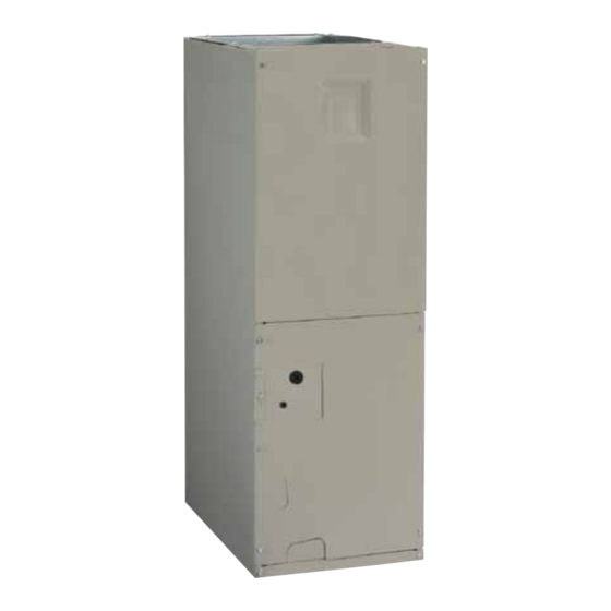
B6BV Series
INStALLAtIoN INStRuctIoNS
AIR HANDLER
For HUD approved installations in manufactured homes and modular homes
It is your responsibility to know this product better than your customer. this includes being
able to install the product according to strict safety guidelines and instructing the customer on
how to operate and maintain the equipment for the life of the product. Safety should always be
the deciding factor when installing this product and using common sense plays an important
role as well. Pay attention to all safety warnings and any other special notes highlighted in the
manual. Improper installation of the furnace or failure to follow safety warnings could result
in serious injury, death, or property damage.
Please read all instructions carefully before starting the installation. these instructions are
primarily intended to assist qualified individuals experienced in the proper installation of this
appliance. Some local codes require licensed installation / service personnel for this type of
equipment. If a problem occurs, check the instructions and follow recommendations given.
If these suggestions don't eliminate your problem, call your servicing contractor. Return this
manual to the customer's package for future reference.
Do Not DEStRoY. PLEASE READ cAREFuLLY & KEEP IN A SAFE PLAcE FoR FutuRE REFERENcE.
IMPoRtANt
AttENtIoN INStALLERS:
Advertisement
Table of Contents

Related Manuals for Nordyne B6BV Series


Summary of Contents for Nordyne B6BV Series
- Page 1 B6BV Series INStALLAtIoN INStRuctIoNS AIR HANDLER For HUD approved installations in manufactured homes and modular homes IMPoRtANt AttENtIoN INStALLERS: It is your responsibility to know this product better than your customer. this includes being able to install the product according to strict safety guidelines and instructing the customer on how to operate and maintain the equipment for the life of the product.
-
Page 2: Table Of Contents
tABLE oF coNtENtS IMPoRtANt SAFEtY INFoRMAtIoN .......3 StARtuP & ADjuStMENtS ........9 Before You Start the Unit ...........9 GENERAL INFoRMAtIoN ..........3 Air Circulation Check ..........9 Requirements & Codes ..........3 Running the Blower Continuously ......9 About the Air Handler ..........3 System Cooling ............9 Mounting Applications ..........3 System Heating ............9 Before You Install this Appliance .......4... -
Page 3: Important Safety Information
Please read all instructions before Requirements & codes installing the unit. The B6BV Series electric furnace is approved for use WARNING: in HUD code manufactured homes (HUD Manufactured this unit must be installed in accordance with... -
Page 4: Before You Install This Appliance
Before You Install this Appliance Minimum clearances √ This equipment is securely packaged at the time of • This appliance must be installed in accordance with shipment and upon arrival should be carefully inspected clearances listed in Table 1. The air handler must be for damage prior to installing the equipment at the job installed with ample clearance for easy access to the site. -
Page 5: Return Air Connections
Air Filters a sidewall. If the return air opening is directly adjacent B6BV series air handlers are not supplied with an air filter to the side (or front) of the air handler, 6” minimum when shipped from the factory. The installer must provide... -
Page 6: Ventilaire Iii Or Iv Air Quality Package
HVAc technicians should install this furnace. The B6BV series air handler is shipped ready for vertical Return upflow installation and is approved for attic, basement, alcove/closet or crawlspace installation with zero clearance Figure 1. -
Page 7: A/C Or H/P Coil Installation
sheet-metal fasteners and seal with an approved foil tape. cabinet Size Description The connector may be field constructed but must meet requirements as listed in the unit installation instructions. Downflow Plenum Connector, 6.25” 913840 914969 1. Measure and mark the outline of the cut-out on the floor. Downflow Plenum Connector, 8.25”... -
Page 8: Electrical Connections
HAZARD of the same gauge and temperature rating. Failure to follow safety warnings exactly could • Circuit breakers installed in the B6BV series air handler result in serious injury or property damage. are for short-circuit protection of the internal wiring and to serve as a unit disconnect. -
Page 9: Thermostat Connections
thermostat connections StARtuP & ADjuStMENtS • Thermostat connections shall be in accordance with the Before You Start the unit instructions supplied with the thermostat. The thermostat Prior to start-up, complete the following inspections: used with this equipment must operate in conjunction √... -
Page 10: Turning The Blower Off
Selecting Continuous Low Speed Fan Operation important to read and follow these directions carefully. The B6BV series air handler is equipped with the option of B6BV air handlers use high efficiency circulating air motors continuous low speed fan operation. When G is energized... -
Page 11: Dehumidification Options
Figure 5. DHuM Wiring configuration B6BV series air handlers are not supplied with a single air filter when shipped from the factory. It is recommended that the filter be cleaned or replaced monthly. Newly built... -
Page 12: Troubleshooting
7. Motor control Board Fault conditions Circuit Breaker (60A) Heating Element Assembly Transformer Motor Control Board Upper Door Assembly Blower Control Wheel Board Capacitor Motor Mount Kit Blower Housing Blower Motor Filter Door Lower Door Assembly Figure 8. B6BV Series Air Handler components... -
Page 13: Figures & Tables
3 5/8” 5 5/8” 13/4” K.O. (typ.) DETAIL “D” “H” 3 1/4” SUCTION 2 1/4” LIQUID 15 1/4” 13” “W” 22" cabinet Size Detail D Tall B 49-5/16 19-11/16 18-1/4 55-15/16 22-7/16 Figure 9. B6BV Series Air Handler Physical Dimensions... -
Page 14: Airflow Data
AIRFLoW DAtA Nominal Electic Heat KW cabinet 1000 1100 1200 1400 1600 1800 2000 table 6. Minimum Heating Airflow Settings (in cFM) for B6BV (FSHE) Air Handlers Nominal Nominal Number of Ext. Static Pressure Medium Medium Model High Blower Size Motor Size Speeds (in W.c.) -
Page 15: Electrical Diagrams & Data
ELEctRIcAL DIAGRAMS & DAtA B6BV 240 VAc, 50 & 60 HZ, SINGLE PHASE 208 VAc, 50 & 60 HZ, SINGLE PHASE HEAt KIt MoDEL cABINEt cAPAcItY NuMBER H6HK- 10 KW 53.6 53.6 47.0 47.0 15 KW 56.6 25.0 78.6 47.0 21.7 68.6 10 KW 56.3... - Page 16 3A Fuse BLWDTC BLWDTC_R COOL HEAT LED 1 HEATER P1 Figure 11. Single Stage control Board LED 1 HEATER P1 Figure 12. two - Stage control Board...
- Page 17 TEST PORT EXPANSION PORT FAN SPEED 1 2 3 4 5 6 7 8 COOL HEAT STATUS BLOWER MOTOR Figure 13. two-Stage Fixed Speed Motor control Board coNtRoL SIGNAL & MoDE oPERAtIoN totAL KW BoARD ActIoN Stage 1 Heat on instantly 5 KW Heat blower on after 3 second delay Stage 1 Heat on instantly...
- Page 18 coNtRoL SIGNAL & MoDE oPERAtIoN totAL KW BoARD ActIoN Stage 1 Heat on instantly 5 KW Heat blower on after 3 second delay Stage 1 Heat on instantly 10 KW Heat blower on after 3 second delay Stage 2 Heat on after 5 seconds delay Stage 1 Heat on instantly Heat blower on after 3 second delay 15 KW...
- Page 19 coNtRoL SIGNAL & MoDE oPERAtIoN totAL KW BoARD ActIoN Stage 1 Heat on instantly 5 KW Cool blower on after 3 second delay Stage 1 Heat on instantly 10 KW Cool blower on after 3 second delay Stage 2 Heat on after 5 seconds delay Stage 1 Heat on instantly Cool blower on after 3 second delay 15 KW...
- Page 20 RELAY Figure 14. Wiring Diagram for B6BV Series Air Handler Equipped With PSc Motor & 10 kw Heater Kit (B Size cabinet only)
- Page 21 RELAY Figure 15. Wiring Diagram for B6BV Series Air Handler Equipped With PSc Motor & 15 kw Heater Kit (B Size cabinet only)
- Page 22 GREEN GREEN YELLOW YELLOW ORANGE ORANGE BROWN BROWN EXPANSION HEATER PLUG 7 6 5 4 3 2 1 Figure 16. Wiring Diagram for B6BV Series Air Handler Equipped With FSHE Motor & 10 kw Heater Kit (c Size cabinet only)
- Page 23 1 2 3 4 5 6 7 8 9 1 2 3 4 5 6 EXPANSION HEATER PLUG 7 6 5 4 3 2 1 Figure 17. Wiring Diagram for B6BV Series Air Handler Equipped With FSHE Motor & 20 kw Heater Kit (c Size cabinet only)
-
Page 24: Installation / Performance Checklist
INStALLAtIoN / PERFoRMANcE cHEcK LISt INStALLER NAME: ELEctRIcAL SYStEM: Electrical connections tight? CITY: STATE: Line voltage polarity correct? _______ Supply Voltage: ____________________________ INStALLAtIoN ADDRESS: Has the thermostat been calibrated? Is the thermostat level? CITY: STATE: Is the heat anticipator setting correct? UNIT MODEL # VENtING SYStEM: UNIT SERIAL #...
Need help?
Do you have a question about the B6BV Series and is the answer not in the manual?
Questions and answers