Table of Contents
Advertisement
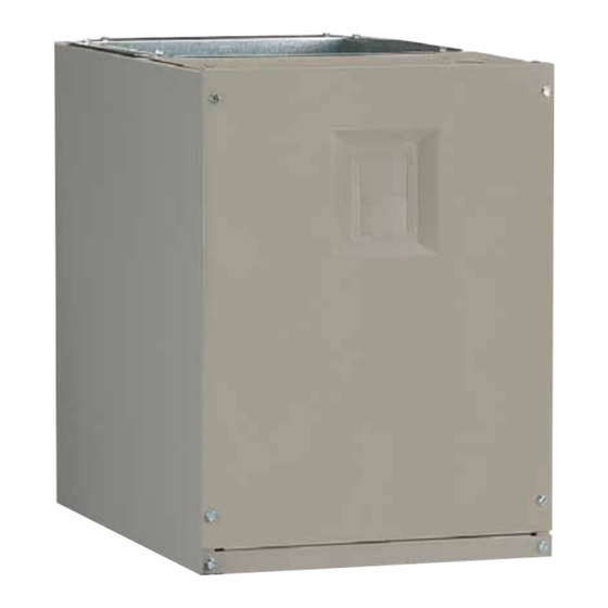
MB7BM, MB7eM, & MB7VM SerieS
inStallation inStructionS
Modular air Handler
it is your responsibility to know this product better than your customer. this includes being
able to install the product according to strict safety guidelines and instructing the customer on
how to operate and maintain the equipment for the life of the product. Safety should always be
the deciding factor when installing this product and using common sense plays an important
role as well. Pay attention to all safety warnings and any other special notes highlighted in the
manual. improper installation of the furnace or failure to follow safety warnings could result
in serious injury, death, or property damage.
Please read all instructions carefully before starting the installation. these instructions are
primarily intended to assist qualified individuals experienced in the proper installation of this
appliance. Some local codes require licensed installation / service personnel for this type of
equipment. if a problem occurs, check the instructions and follow recommendations given.
if these suggestions don't eliminate your problem, call your servicing contractor. return this
manual to the customer's package for future reference.
do not deStroY. PleaSe read careFullY & KeeP in a SaFe Place For Future reFerence.
iMPortant
attention inStallerS:
Advertisement
Table of Contents

Subscribe to Our Youtube Channel
Related Manuals for Nordyne MB7BM Series


Summary of Contents for Nordyne MB7BM Series
- Page 1 MB7BM, MB7eM, & MB7VM SerieS inStallation inStructionS Modular air Handler iMPortant attention inStallerS: it is your responsibility to know this product better than your customer. this includes being able to install the product according to strict safety guidelines and instructing the customer on how to operate and maintain the equipment for the life of the product.
-
Page 2: Table Of Contents
taBle oF contentS iMPortant SaFetY inForMation .......3 StartuP & adjuStMentS ........11 Before You Start the Air Handler......11 General inForMation ..........3 Air Circulation Check ..........11 Requirements & Codes ..........3 Running the Blower Continuously ......11 About the Air Handler ..........3 System Cooling ............11 Before You Install this Equipment ......4 System Heating ............11 Minimum Clearances ..........4... -
Page 3: Important Safety Information
iMPortant SaFetY inForMation thoroughly understand the instructions provided with the equipment prior to performing the installation and Please read all information in this manual thoroughly operational checkout of the equipment. and become familiar with the capabilities and use of this •... -
Page 4: Before You Install This Equipment
Before You install this equipment locating the air Handler √ This equipment is securely packaged at the time of • Survey the job site to determine the best location for shipment and upon arrival should be carefully inspected mounting the unit. Consideration should be given to for damage prior to installing the equipment at the job availability of electric power, service access, and noise. -
Page 5: Plenums & Air Ducts
• It is good practice to seal all connections and joints Plenums & air ducts • Plenums and air ducts should be installed in with industrial grade sealing tape or liquid sealant. Requirements for sealing ducts vary from region to accordance with the standards of the National Fire region. -
Page 6: Air Filters
• Modular air handlers are intended to be mated with surface). Make sure there are no gaps on the front and specific NORDYNE C6 cased coils. To ensure proper side flanges. condensate drainage, the unit must be installed in a 2. -
Page 7: Downflow Installation
downflow installation The MB7 Series Modular air handler may be installed in a downflow configuration as shown in Figure 1. Return air must enter through the top of the unit. 1. Remove the lower front bracket (Figure 3) from the modular unit. -
Page 8: Horizontal Installation
Horizontal installation 4. Place the horizontal drain pan on the opposite side of MB7 air handlers are shipped from the factory ready the coil. On units with 2 sets of knockouts, remove the for horizontal left applications and horizontal right other set of knockouts in the coil spacing plates and applications. -
Page 9: Electrical Connections
electrical connectionS a conduit connector for connecting the supply wires to the unit. Aluminum supply wire may be used if a heater kit is installed. WarninG: • If replacing any of the original wires supplied with the unit, the replacement wire must be copper wire consisting electrical SHocK, Fire or eXPloSion of the same gauge and temperature rating. -
Page 10: Control Board
important! On variable speed models when the unit is If a heater kit is not installed: used in an air conditioning system, connect the o terminal 1. Remove the 2 wire plug of the air handler by cutting the to the Y terminal. See Figure 9 (page 20). wires and discarding the plug. -
Page 11: Startup & Adjustments
StartuP & adjuStMentS Blower configurations Selecting Minimum Electric Heat Airflow Before You Start the air Handler The minimum electric heat airflow setting controls the Prior to start-up, complete the following inspections: minimum air flow that will be produced whenever electric √... -
Page 12: High Efficiency Units
• For maximum capacity and energy efficiency, select an 3. Connect the heating speed wire (red) and the cooling speed wire (black) to the desired blower speed marked airflow at or near the top of the range for that nominal on the terminal block of the blower motor. -
Page 13: Unit Maintenance
unit Maintenance Blower Fan Wheel Inspect the blower wheel blades for accumulations of dirt Proper maintenance is most important to achieve the best and clean if necessary. Inspect mounting nut for tightness. performance from an air handler. Some of the components and their locations are shown in Figure 8 (page 15). -
Page 14: Figures & Tables
FiGureS & taBleS 3/4 TYP. 3/4 TYP. 12 7/8 VIEW Ø1 1/8” K.O. "A" (TYP.) 1 1/4 Ø 1 7/8 K.O. 2 7/8 1 3/4 1 1/4 3 1/4 2 5/8 1” 1 7/8 1 7/8 3 1/2 5 1/2 Ø... -
Page 15: Figure 8. Mb7 Series Components
Outlet Heater Box Heating Element Assembly Transformer Control Board Blower Wheel Blower Blower Rear Housing Door Bracket Motor Control Blower Board Motor Motor Lower Front Mount Kit Bracket Front Joining Bracket Coil Assembly Figure 8. MB7 Series component locations... -
Page 16: Blower Performance Data
BloWer PerForMance data MB7BM airflow data Dry Coil ESP 0.10 0.20 0.30 0.40 0.50 0.60 0.70 0.80 Corrected ESP 0.07 0.19 0.30 0.42 0.53 0.65 0.76 0800 a-cabinet Corrected ESP 0.11 0.23 0.36 0.48 0.60 0.72 High 1070 1025 Corrected ESP 0.14 0.27 0.40... - Page 17 cooling or Heating airflow (cFM) Switch Settings 0 = oFF, 1 = on dry coil eSP 1/5 2/6 3/7 4/8 1030 B7eM 1115 1085 1060 1020 a-cabinet 1155 1130 1095 1070 1040 1010 1200 1175 1145 1110 1085 1060 1025 1000 1240 1215...
- Page 18 nominal electic Heat KW cabinet 1000 1300 1000 1100 1300 1500 1000 1100 1200 1400 1600 note: See Table 6 for appropriate switch settings for these airflows. table 6. Minimum Heating airflow Settings (in cFM) for MB7eM (FSHe) air Handlers a-caBinet SWitcH SettinGS noMinal...
- Page 19 cooling airflow Heating airflow cool Switch Setting a/B Switch Setting airflow a/B Switch Setting Heater Kit airflow 0 = OFF, 1 = ON 0 = OFF, 1 = ON 0 = OFF, 1 = ON (cFM) installed (KW) (cFM) 1000 1000 1300 B7VM...
-
Page 20: Electrical Data & Diagrams
electrical data & diaGraMS MB7BM 240 Vac, 50 & 60 HZ, SinGle PHaSe 208 Vac, 50 & 60 HZ, SinGle PHaSe Heat Ki Model caBinet caPacitY nuMBer 6HK- None 005H-XX 26.6 26.6 23.3 23.3 008H-XX 41.2 41.2 35.9 35.9 800CFM 010H-XX 51.6 51.6... - Page 21 Thermostat Thermostat Thermostat NOTE: Jumper W1 & W2 together if not using W2 on thermostat Conditioner Handler Conditioner Conditioner Y/Y2 Y/Y2 Handler Handler Typical Air Conditioner with Typical Air Conditioner with Typical 2-Stage Air Conditioner Standard Air Handler Variable Speed Air Handler with Variable Speed Air Handler Thermostat Thermostat...
- Page 22 3A Fuse BLWDTC BLWDTC_R COOL HEAT LED 1 HEATER P1 Figure 10. Single Stage control Board (MB7BM Models) LED 1 HEATER P1 Figure 11. two - Stage control Board (MB7eM / VM Models)
- Page 23 TEST PORT EXPANSION PORT FAN SPEED 1 2 3 4 5 6 7 8 COOL HEAT STATUS BLOWER MOTOR Figure 12. Fixed Speed Motor control Board (MB7eM Models) STATUS LIGHTS L2-IN L2-OUT Y/Y2 L1-IN L1-OUT DEHUM FAN SPEED 2 3 4 5 6 7 8 TEST PORT COOL HEAT...
- Page 24 RELAY Figure 14. Wiring diagram for MB7BM Series air Handler...
- Page 25 BLUE BLUE GREEN GREEN YELLOW YELLOW ORANGE ORANGE BROWN BROWN EXPANSION HEATER PLUG Figure 15. Wiring diagram for MB7eM Series air Handler...
- Page 26 WHITE BLACK 1 2 3 4 5 6 1 2 3 4 5 6 7 8 9 1 2 3 4 5 6 7 8 9 1 2 3 4 5 6 EXPANSION HEATER PLUG Figure 16. Wiring diagram for MB7VM Series air Handler...
- Page 27 control SiGnal & Mode oPeration total KW Board action Stage 1 Heat on instantly 5 KW Heat blower on after 3 second delay Stage 1 Heat on instantly 10 KW Heat blower on after 3 second delay Stage 2 Heat on after 5 seconds delay Stage 1 Heat on instantly Heat blower on after 3 second delay 15 KW...
- Page 28 control SiGnal & Mode oPeration total KW Board action Stage 1 Heat on instantly 5 KW Heat blower on after 3 second delay Stage 1 Heat on instantly 10 KW Heat blower on after 3 second delay Stage 1 Heat on instantly 15 KW Heat blower on after 3 second delay W1 only...
- Page 29 control SiGnal & Mode oPeration total KW Board action Stage 1 Heat on instantly 5 KW Cool blower on after 3 second delay Stage 1 Heat on instantly 10 KW Cool blower on after 3 second delay Stage 1 Heat on instantly 15 KW Cool blower on after 3 second delay W1 &...
-
Page 32: Installation / Performance Checklist
inStallation / PerForMance cHecK liSt inStaller naMe: electrical SYSteM: Electrical connections tight? CITY: STATE: Line voltage polarity correct? _______ Supply Voltage: ____________________________ inStallation addreSS: Has the thermostat been calibrated? Is the thermostat level? CITY: STATE: Is the heat anticipator setting correct? UNIT MODEL # attention inStallerS: It is your responsibility to know this product better than your customer.
Need help?
Do you have a question about the MB7BM Series and is the answer not in the manual?
Questions and answers