
Related Manuals for Singer 491D


Summary of Contents for Singer 491D
- Page 1 SEWING MACHINE SERVICE MANUAL FOR SINGER 491D SEWING MACHINE PARTS CHART FOR 491D200GA & 491D300GA...
- Page 2 Restored from web copy Available from Internet Archive archive.org...
- Page 3 Form U251 (1273) Service Manual Machine THE SINGER COMPANY...
-
Page 4: Table Of Contents
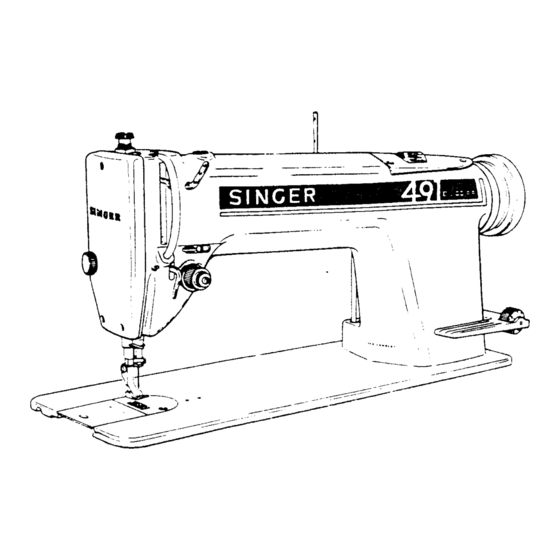
......18 - 21 * A Trademark of THE SINGER COMPANY Copyright © 1973 THE SINGER COMPANY... - Page 5 DESCRIPTION Class 491D Machines are high speed, rotary hook, fully automatic lubricated long arm flat bed lockstitch machines with drop feed and hand operated reverse feeding mechanism. Recommended for general stitching operations on a range of light to heavyweight fabrics.
-
Page 6: To Set Needle Bar At Correct Height
TO SET NEEDLE BAR AT CORRECT HEIGHT PREPARATION: TIMING Remove face plate, slide MARK plate and throat plate. See that needle is correctly set in needle bar. Lower end of bushing A, Fig. 2 must be set as shown in Fig. 2. To reset bushing, loosen screw B. -
Page 7: To Set Check Spring Tension
SETTING: Loosen screw E, Fig. 3. Turn stud F, Fig. 3 (at the same time turning entire ten- sion assembly) either over toward left to lower check spring and decrease its movement, or over toward right to raise check spring HIGHER and increase its movement. -
Page 8: To Set Presser Bar At Correct Height
TO SET PRESSER BAR AT CORRECT HEIGHT CLEARANCE AT LOWEST FOOT RESTING POINT AT HIGHEST FIRMLY POINT UPON JUST THROAT CLEAR PLATE Fig. 5 Fig. 6 PREPARATION: Remove face plate and slide plate. CHECK: 1. When presser foot rests firmly upon throat plate (with feed dog below throat plate) there should still be some clearance between guide bracket G, Fig. -
Page 9: To Time The Sewing Hook And Also Set The Sewing Hook Sidewise In Relation To The Needle
TO TIME THE SEWING HOOK AND ALSO SET THE SEWING HOOK SIDEWISE IN RELATION TO THE NEEDLE PREPARATION: Remove presser foot, slide plate, throat LOWER plate and feed dog. TIMING MARK CHECK: When lower timing mark on needle bar is HOOK POINT level with lower end of lower needle bar AT CENTER... -
Page 10: Feed Reverse Lever
FEED REVERSE LEVER Before the machine leaves the factory, the spring tension of the feed reverse lever is set at an appropriate tension for easy and comfortable sewing operation. If it is necessary to adjust the feed reverse lever spring tension, tip machine back and loosen feed reverse lever spring retainer screw Y3 holding the spring retainer 23 on the machine leg. -
Page 11: To Set Feed Dog At Correct Height
NOTE: Whenever the timing of the feed is changed, sewing hook should be checked for necessary adjustment also, as instructed on page 5. TO SET FEED DOG AT CORRECT HEIGHT FULL DEPTH OF TEETH THROAT PLATE Fig. 12 When the feed dog is at its highest position, approximately the full depth of all the teeth should project above the top surface of the throat plate, as shown in Fig. -
Page 12: Removal And Replacement Of Principal Assemblies
REMOVAL AND REPLACEMENT PRINCIPAL ASSEMBLIES CAUTION TO MECHANICS Machines of Class 491D are made with extreme precision in machining and assembly, and the "Superfinish" process provides microscopically smooth bearing surfaces. Therefore, special care should be taken not to permit any misalign- ment of parts or to cause any scratches or nicks on the bearing surfaces by careless assembly or handling of parts. -
Page 13: To Replace Oil Filter 143042
TO REPLACE OIL FILTER 143042 While the sewing hook is off the shaft, it is advisable to replace the oil filter 143042, Fig. 15 in the end of the hook shaft. Unscrew the filter from the center of the shaft at X, Fig. 15 and replace with a complete new filter 143042. -
Page 14: To Remove And Replace The Hook Shaft
TO REMOVE AND REPLACE THE HOOK SHAFT HOLD GEARS IN MESH HOOK SHAFT Fig. 17 Remove and replace the hook shaft in the following manner:- 1. Remove the sewing hook, as instructed on page 8. 2. Mark the two lower bevel gears Z and T, Fig. 17, with chalk or crayon, on one tooth of one gear and the corresponding space for that tooth in the other gear. -
Page 15: The Oil Pump
THE OIL PUMP TO LOOSEN Fig. 18 TO REMOVE 1. Loosen the two oil pipe clamping sleeve nuts A2, Fig. 18. 2. Remove the three screws B2, Fig. 17. 3. Remove the screen frame, screen and oil pump cover C2, Fig. 17, 4. -
Page 16: To Remove And Replace The Upright Arm Shaft
TO REMOVE AND REPLACE THE UPRIGHT ARM SHAFT (See Fig. 19) Fig. 19 REMOVAL: If it is found necessary to remove the upright arm shaft H2, it should be removed in the following manner:- 1. Remove oil pump, as instructed on page 11. 2. -
Page 17: To Remove And Replace The Needle Bar
3. Turn shaft so that one of the two set screws K2 will bear upon the upper gear flat on the shaft and tighten the set screws K2. 4. Replace and set hook shaft bevel gear as instructed in Step 5 on page 10. 5. -
Page 18: To Remove And Replace The Presser Bar
TO REMOVE AND REPLACE THE PRESSER BAR To remove the presser bar:- 1. Remove presser foot and face plate. 2. Remove presser bar pressure regulating thumb screw R2, with presser bar guide from head of the machine. 3. Loosen clamping screw J about one turn (just enough to make it loose). 4. - Page 19 3. Turn machine pulley as required to reach screw T2, Fig. 22, in needle bar crank through hole left by removal of plug S2, Loosen set screw T2. 4. Using wrench 545945 (through same hole) and turning machine pulley as re- quired, loosen the large hexagon head clamping screw U2, Fig.
-
Page 20: To Remove And Replace Arm Side Shield Wick, Needle Bar Wick And Needle Bar Connecting Stud Wick
11. Using wrench 545945, through same hole and turning machine pulley as re- quired, tighten hexagon head screw U2 lightly. 12. Loosen set screw T2. 13. Securely tighten clamping screw U2, 14. Securely tighten set screw T2. 15. Push hinge stud Y2 fully into machine casting and securely tighten set screw W2. -
Page 21: To Remove Oil Wick Holder
TO REMOVE OIL WICK HOLDER (See Fig. 24) Oil wick holder includes two oil wick leaders (see Fig. 25) and an oil wick for the needle bar link and for the two sets of needle THESE bearings in the thread take-up as shown in THESE LOOPS LOOPS... -
Page 22: The Arm Shaft
4. When oil wick leaders are correctly installed, replace holder screw H3, Fig. 25. 5. Adjust the three oil wick loops in holder (see Figs. 24 and 25), so that two of the loops come as close as possible to, without touching, the two sets of needle bearings B3 while the third wick loop makes positive contact with the wick inside the stud Y2, in the needle bar link, as shown in Fig. - Page 23 9. Loosen the two set screws S3, Fig. 28 and remove the machine pulley. 10. Turn the needle bar crank until it is in the position shown at T3, Fig. 30, to prevent crank from disturbing the three wick loops in holder U3, Fig.
- Page 24 REPLACEMENT (See Fig. 31) HOLD GEARS IN MESH Fig. 31 1. Insert the machine-pulley-end of the arm shaft into the arm shaft bushing at the head of the machine arm. 2. Make certain that the needle bar crank is turned to the position shown in Fig.
- Page 25 9. Check the adjustment and timing of parts disturbed and correct where necessary, according to the instructions on pages 2 through 7. 10. Replace thread take-up, as instructed on pages 15 and 16. ll. Replace presser bar and presser foot, as instructed on page 14. 12.
- Page 26 Copyright © 1973 THE SINGER COMPANY All Rights Reserved Throughout the World...
- Page 27 491D200GA,D300GA...
- Page 28 BLANK...
- Page 29 Form U250 (Rev. 1177) (Rev. 2) MACHINE PARTS CHART D200GA D300GA * A Trademark of THE SINGER COMPANY Copyright © 1973 THE SINGER COMPANY All Rights Reserved Throughout the World...
- Page 30 BLANK...
- Page 31 NUMERICAL LIST OF PARTS FOR MACHINE 491D200GA PART NO. DESCRIPTION PART NO. DESCRIPTION 229 (805) Rotating Hook Oil Flow Regulating Thumb Screw 504134 (850) Feed Reverse Lever Hinge Stud Collar Set Screw 504134 (850) Rotating Hook Shaft Oil Retaining Collar Set Spring Screw 691-845 Throat Plate Screw (2)
- Page 32 NUMERICAL LIST OF PARTS FOR MACHINE 491D200GA PART NO. DESCRIPTION PART NO. DESCRIPTION 540645 Feed Rock Shaft Driving Frame complete, Nos. 545043 (819) Feed Lifting Rock Shaft Crank (front) Clamping 540635, 540636, 540639, 540642, 540644, Screw 540648, 540649, 540650, 540652, 548091, 545046 (819) Feed Reverse Lever Clamping Screw 549384, two each 540655, 540656, 540657...
- Page 33 Presser Bar Guide Bracket with 545099 541515-001 Cloth Guide (purchased part) 545987 Feed Bar 545927 Oil Can (950 cc, filled with Singer Type "C" 545990 Rotating Hook and Rotating Hook Bobbin Case Oil) Holder complete, Nos. 545951 and 545994 548701...
- Page 34 BLANK...
- Page 35 546933 504129 12431-452 149031 504063 CAT. 1901 545881 52033-452 504007 55623 154884 545837 505643 504084 504051 154789 540770 549182 540769 545955 545951 505351 504086 540767 549187 545991 505353 505355 545954 545950 504087 505354 549186 545994 505356 504032 545990 SINGER 491D...
- Page 36 BLANK...
- Page 37 545836 504101 504013 (3) 545949 143236 143042 540536 504002 545542 549183 272111 545807 545883 540537 505647 545987 504002 549396 545884 545789 540539 545808 143236 504103 504103 540544 504007 143236 504111 540541 545043 545810 545810 545806 545949 504111 540540 SINGER 491D...
- Page 38 BLANK...
- Page 39 549383 504029 504134 545492 540637 545854 545046 540714 540630 548479 549382 540689 504134 540690 540624 504071 540623 540628 545825 504051 540625 545047 545856 545033 540629 545049 545753 540631 545855 545776 540633 545777 545857 545858 504064 545050 545034 505001 SINGER 491D...
- Page 40 BLANK...
- Page 41 PARTS FOR 491D300GA MACHINE A C C E S S O R I E S A N D AT TA C H M E N T S WHICH DIFFER FROM 491D200GA MACHINE CAT. 1901 41400 545051 545909 (2) 55623 543364 548701 549184-001 543366...
- Page 42 BLANK...
- Page 43 BLANK...
- Page 44 Copyright © 1973 THE SINGER COMPANY All Rights Reserved Throughout the World...
Need help?
Do you have a question about the 491D and is the answer not in the manual?
Questions and answers