
Related Manuals for Lochinvar BMS

Summary of Contents for Lochinvar BMS
- Page 1 BMS Interface Installation, Commissioning & User Instructions LV 311273 | June 2022...
- Page 2 IMPORTANT INFORMATION These instructions must be read and understood before installing, commissioning, operating or maintaining the equipment.
- Page 3 Read this manual Warning carefully Read this manual carefully before starting the BMS Interface. Failure to read the manual and to follow the printed instructions may lead to personal injury and damage to the BSM Interface, water heater or any other equipment.
-
Page 4: Table Of Contents
Installation, Commissioning & User Instructions Content Lay-out .......................... 5 Introduction ........................5 Lay-out ........................... 5 Mounting and Installing ....................6 Introduction ........................6 Mounting ......................... 6 Connecting ........................6 Settings ......................... 9 Data readout ......................... 10 Introduction ........................10 Parameters ........................11 Errors ........................... -
Page 5: Lay-Out
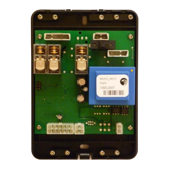
The BMS Interface does not have its own display or push buttons. Schematic sketch BMS Interface IMD-1155 R0.0 Lay-out The BMS Interface will be supplied as in the pictured below, with a black plastic housing. Lochinvar Ltd. - www.lochinvar.ltd.uk... -
Page 6: Mounting And Installing
The BMS Interface should be mounted in the following way: 1. Remove the cover of the BMS Interface 2. Mount the rear side of the BMS Interface to the wall with fitting plugs. 2.3 Connecting The BMS Interface should be connected to the BMS and water heater in the following way: 1. - Page 7 First connect the twelve way connector containing the ground wire, next the four way connector can be connected. 5. Connect the Modbus communication cable to the BMS in the required way. For this purpose use the connectors which are supplied together with the BMS Interface.
- Page 8 Installation, Commissioning & User Instructions 6. Connect the cable from the BMS to the supplied contra connector. First lead the cable through the strain relief. This three wire cable (2 wires + PE) is not supplied with the BMS Interface. Make sure that the wires are connected in the right sequence.
-
Page 9: Settings
Installation, Commissioning & User Instructions 3 Settings To approach the BMS Interface, from the BMS, some settings need to be made in order to make the communication possible. Setting Value Type Modbus RTU Baud rate 9600 Initial address Data bits... -
Page 10: Data Readout
4 Data readout 4.1 Introduction The BMS Interface supplies data, in a Modbus format, to the BMS. The user will receive this data and needs to process this. The attached parameter list can be used. Pay special attention to some of the data that has to be converted into the wright format before receiving the expected values. -
Page 11: Parameters
Description Setting y = first byte meter type x = second byte 16 bits direct Address Actual Modbus address BMS Interface 16 bits direct Temperature °C Temperature in the top of the water heater x/100 16 bits direct Temperature °C... - Page 12 Actual heat input in % of the maximum load 16 bits direct Relay Relay: Error activated 1=Closed, 0=Open 16 bits direct Temperature °C CV setpoint x/100 16 bits direct Temperature °C CV temperature x/100 16 bits direct Relay Relay: Heat demand roomthermostat 1=Closed, 0=Open Lochinvar Ltd. - www.lochinvar.ltd.uk...
-
Page 13: Errors
5 Errors Introduction Through the BMS Interface, internal error codes can be viewed. On parameter 20, the actual error code for lock outs and blocking errors are displayed. Parameters 10 … 14, 15 … 19 and 23 … 27 show the five most recent errors of respectively the lock outs, blocking errors and solar errors. -
Page 14: Lock-Out Codes
Top tank sensor 2 open Bottom tank sensor shorted Flue gas sensor 1 shorted Flue gas sensor 2 shorted Top tank sensor 1 shorted Top tank sensor 2 shorted Reset error Selection error Supply voltage error No error Lochinvar Ltd. - www.lochinvar.ltd.uk... -
Page 15: Status
6 Status Introduction Via the BMS Interface, the state of the water heater and the solar control can be read out separately. The actual state of the control of the water heater can be found on parameter Status water heater The numbers that will be read out refer to certain states of the control(s). - Page 16 Installation, Commissioning & User Instructions 0311 273 R2.1 EN Lochinvar Ltd. - www.lochinvar.ltd.uk...
- Page 17 Lochinvar Ltd reserves the right to change 8 Lombard Way, The MXL Centre, Banbury, Oxon, OX16 4TJ specifications without prior notice Tel: +44(0) 1295 269 981, Fax:+44(0) 1295 271 640, Email: info@lochinvar.ltd.uk www.lochinvar.ltd.uk...
Need help?
Do you have a question about the BMS and is the answer not in the manual?
Questions and answers