Table of Contents
Advertisement
FB-SER_100161013_2000004598 Rev R
Service Manual
w/CON•X•US Interface
Models:
2500 - 6000
This manual must only be used
WARNING
by a qualified heating installer
/ service technician. Read
all
instructions,
this manual and the Crest
Installation and Operation
Manual,
Perform steps in the order
given. Failure to comply could
result in severe personal injury,
death, or substantial property
damage.
Save this manual for future reference.
including
before
installing.
Advertisement
Table of Contents

Related Manuals for Lochinvar SMART TOUCH w/CON-X-US

Summary of Contents for Lochinvar SMART TOUCH w/CON-X-US
- Page 1 FB-SER_100161013_2000004598 Rev R Service Manual w/CON•X•US Interface Models: 2500 - 6000 This manual must only be used WARNING by a qualified heating installer / service technician. Read instructions, including this manual and the Crest Installation and Operation Manual, before installing. Perform steps in the order given.
-
Page 2: Table Of Contents
Contents Night Setback Screen ........... 25 CONTENTS ................ 2 Pump Screen ............26-27 Hazard Definitions .............. 2 Cascade Screens ............28-30 PLEASE READ BEFORE PROCEEDING ......3 Service Screen............31-32 Handling Ceramic Fiber Materials ........3 Graph Screens .............. 33 When servicing boiler ........... 4 History Screens............34-35 Boiler operation ............ -
Page 3: Please Read Before Proceeding
Service Manual Please read before proceeding Installer – Read all instructions, including When calling or writing about the boiler WARNING NOTICE this manual and the Crest Installation – Please have the boiler model and serial and Operation Manual, before installing. number from the boiler rating plate. -
Page 4: When Servicing Boiler
Service Manual Please read before proceeding When servicing boiler – • To avoid electric shock, disconnect electrical supply before performing maintenance. • To avoid severe burns, allow boiler to cool before performing maintenance. Boiler operation – • Do not block flow of combustion or ventilation air to the boiler. -
Page 5: What Is In This Manual
Service Manual What is in this manual? Service Maintenance Near boiler piping • Service and maintenance schedules • Address reported problems • Typical system components • Inspect boiler area and boiler interior The Crest boiler display • Clean condensate trap •... -
Page 6: Service Boiler Piping
Service Manual Service Boiler piping This piping reference is included to specify the Boiler Piping specific to the Crest boiler. This piping scheme is important for proper operation of the SMART TOUCH control. See the Crest Installation and Operation Manual for more detailed piping diagrams. -
Page 7: Smart Touch W/Con•X•Us Interface
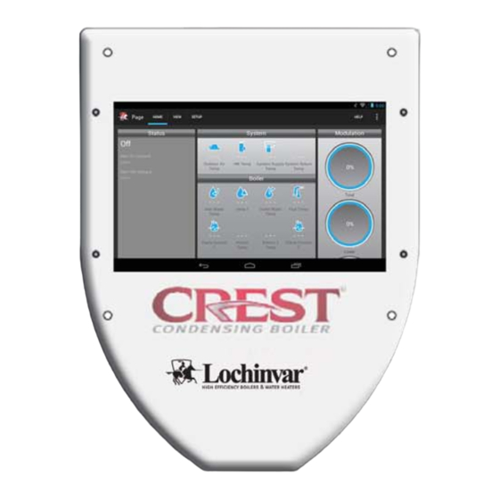
Service Manual Service (continued) w/CON•X•US Interface The Home Screen displays status, modulation rate, outlet water temperature, inlet water temperature, flue temperature, system supply temperature, system return temperature, outdoor air temperature, and domestic hot water tank temperature. The boiler can be started and stopped by pressing the ON/OFF button. The Boiler Status Screen and Main Menu Screen can be accessed by pressing the appropriate button. -
Page 8: General Operation
Service Manual Service General Operation How the boiler operates Sequence of operation Table 1A (page 11) shows control module normal sequences of The Crest uses an advanced stainless steel heat exchanger operation for space heating and HW operation. The combined and electronic control module that allows fully condensing operation sequence is for a typical application, programmed to operation. -
Page 9: Control Inputs
Service Manual Service Service (continued) Control inputs HWG THERMOSTAT / SENSOR ENABLING DEVICE CASCADE LOW VOLTAGE CONNECTION LOUVER PROVING SWITCH BOARD SYSTEM SENSOR - SUPPLY SYSTEM SENSOR - RETURN OUTDOOR SENSOR BAS BOARD SEQUENCER / BUILDING MANAGEMENT SYSTEM AUX SWITCH 1 & 2 SMART CONTROL 0-10 INPUT FROM MODULE... -
Page 10: Control Outputs
Service Manual Service Service Control outputs 0-10V OUTPUT TO BOILER PUMP ALARM CONTACTS LOW VOLTAGE CONNECTION LOUVER RELAY BOARD RUN TIME CONTACTS BOILER RATE OUTPUT SEQUENCER / BUILDING MANAGEMENT SYSTEM LINE VOLTAGE TERMINAL STRIP BOILER PUMP CONTACTOR SYSTEM PUMP CONTACTOR HWG PUMP CONTACTOR IGNITOR... - Page 11 Service Manual Service (continued) Table 1A Sequence of Operation Sequence of operation Note: This unit is equipped with two (2) gas train systems. Gas Train 1 will fire first. If the demand cannot be met by the first gas train, the second gas train (Gas Train 2) will fire. Upon a call for heat, the control turns on the appropriate pumps (system and boiler pumps for a space heating call, HW pump for a hot water generator call).
-
Page 12: Initial Setup Screen
Service Manual Service Initial Setup Screen Figure 1-2 Rapid Setup A Initial Setup Clock and Date The control uses an internal clock for the night setback feature and for logging of events. For these features to work correctly, the clock must be set when the boiler is first installed or anytime the boiler has been powered off for more than four (4) hours. -
Page 13: Viewable And Changeable Control Parameters
Service Manual Service (continued) Viewable and changeable control parameters Before changing parameters, note the settings so that the unit can be returned to its original operating CAUTION parameters. Set Point Screens Figure 1-3 Set points HW_Screen A Figure 1-4 Set points HW_Screen B... - Page 14 Service Manual Service Figure 1-5 Set points SH_Screen A Service Table 1B Set Points (This table lists control module parameters; use the sub-tab under the Setup tab to access them.) Default Parameter Name Menu (as shown on the LCD screen) Value Value Value...
- Page 15 Service Manual Service (continued) Set Points HW Boiler Set Point: Set point When a HW call for heat becomes active, the control will use Space Heat 1 Set Point: Set point the HW boiler set point to determine the firing rate of the boiler based on the boiler outlet water temperature.
-
Page 16: Outdoor Reset Screen
Service Manual Service Outdoor Reset Screen Figure 1-6 Outdoor Reset A Table 1C Outdoor Reset (This table lists control module parameters; use the sub-tab under the Setup tab to access them.) Default Parameter Name Menu (as shown on the LCD screen) Value Value Value... - Page 17 Service Manual Service (continued) Outdoor Reset Boost Temperature If a SH demand lasts longer than the programmed boost time Outdoor Reset Curve delay setting and there have been no HW demands, the control The Outdoor Temp Min and Set Point Max define the will increase the water temperature set point by the amount in upper point of the Outdoor Reset Curve.
-
Page 18: Ramp Delay Screen
Service Manual Service Ramp Delay Screen Figure 1-7 Ramp Delay Table 1D Ramp Delay (This table lists control module parameters; use the sub-tab under the Setup tab to access them.) Default Parameter Name Menu (as shown on the LCD screen) Value Value Value... - Page 19 Service Manual Service (continued) Ramp Delay Ramp Delay (Enable / Disable) This parameter allows the installer to enable or disable the SH ramp delay. SH Ramp Delay The SMART TOUCH CON•X•US Interface can be programmed to limit the firing rate for a fixed period of time at the start of a space heating demand.
-
Page 20: Bms Screens
Service Manual Service BMS Screens Figure 1-8 BMS_Screen A Figure 1-9 BMS_Screen B... - Page 21 Service Manual Service (continued) Table 1E BMS / BAS (This table lists control module parameters; use the sub-tab under the Setup tab to access them.) Default Parameter Name Menu (as shown on the LCD screen) Value Value Value BMS Status ACTIVE INACTIVE INACTIVE...
- Page 22 Service Manual Service BMS Set Point at Minimum Volts This parameter is visible only when the BMS Mode is set to BAS Active / Inactive SETPOINT. The value of this parameter determines the set The boiler is capable of being monitored and/or controlled point when the voltage on the 0 - 10V BMS input is equal to by a Building Automation System (BAS) through either a or less than the BMS Volts at Minimum parameter value.
-
Page 23: Advanced Setup Screen
Service Manual Service (continued) Advanced Setup Screen Figure 1-10 Advanced Setup Table 1F Advanced Setup (This table lists control module parameters; use the sub-tab under the Setup tab to access them.) Default Parameter Name Menu (as shown on the LCD screen) Value Value Value... - Page 24 Service Manual Service Freeze Protection Burner Off Once the burner has started firing due to a low inlet temperature, the inlet temperature must increase by this amount before the burner turns back off. The installer can adjust this differential by accessing the Freeze Protection Burner Off parameter. Anti-Cycling Time Once a SH demand has been satisfied, a set amount of time must elapse before the control will respond to a new SH...
-
Page 25: Night Setback Screen
Service Manual Service (continued) Night Setback Screen Figure 1-11 SH Night Setback Table 1G SH/HW Night Setback (This table lists control module parameters; use the sub-tab under the Setup tab to access them.) Default Parameter Name Menu (as shown on the LCD screen) Value Value Value... -
Page 26: Pump Screen
Service Manual Service Pump Screen Figure 1-12 Pump Table 1H Pumps (This table lists control module parameters; use the sub-tab under the Setup tab to access them.) Default Parameter Name Menu (as shown on the LCD screen) Value Value Value System Pump Mode Boiler Pump Delay 0:00... - Page 27 Service Manual Service (continued) Pumps HW System Pump Mode This parameter allows the installer to determine how the system System Pump Mode pump responds to a HW call for heat. The parameter can be The SMART TOUCH control is able to control the system adjusted through the HW System Pump Mode parameter.
-
Page 28: Cascade Screens
Service Manual Service Cascade Screens Figure 1-13 Cascade Setup Screen A Figure 1-14 Cascade Leader Setup... - Page 29 Service Manual Service (continued) Table 1I Cascade (This table lists control module parameters; use the sub-tab under the Setup tab to access them. Default Parameter Name Menu (as shown on the LCD screen) Value Value Value Cascade Address Cascade Status ENABLE DISABLE DISABLE...
- Page 30 Service Manual Service L/L: Lead/Lag Blocking Time Switching Boiler On / Off This method is used when it is desired to run the least In order to prevent units in a Cascade from short cycling, number of boilers as possible. When the first boiler reaches this parameter defines the minimum ON and OFF time for 100% and calculated demand is still greater, the Cascade will each unit.
-
Page 31: Service Screen
Service Manual Service (continued) Service Screens Th e Service Screen allows the integrated control to override all other heat demands and operate Valve 1 and Valve 2 at high fi re and low fi re conditions. To place the boiler into Service Mode, press the START button. As specifi ed above the integrated control will override all other heat demands, however, all safeties will be active. - Page 32 Service Manual Service Figure 1-16 Service Notification Table 1J Service Notification (This table lists control module parameters; use the sub-tab under the Setup tab to access them. Default Parameter Name Menu (as shown on the LCD screen) Value Value Value Maintenance Notice By: Months Maintenance Notice By: Running Hours 100,000...
-
Page 33: Graph Screens
Service Manual Service (continued) Graph Screens Th e Graph Screen consists of two (2) diff erent types of screens. Th e fi rst screen Short Term Data Screen (three minutes in one second intervals) and the Long Term Data Screen (32 days, 233 averages ?) If a parameter is selected by mistake, it can be de-selected by re- selecting the parameter. -
Page 34: History Screens
Service Manual Service History Screen Th e History Screen shows the status of various counters and faults. Within the History Screen there are two separate screens. Th ese screens are the “Lockout Blocking Fault” and “Runtime History”. Th e default screen is the “Lockout Blocking Fault” screen. Th is screen allows you to view the last 20 lockout/blocking faults. Succeeded by each fault is the date and time of when the fault occurred. - Page 35 Service Manual Service (continued) Th e third screen is the “Runtime History”. Th ere are several pieces of information that are displayed on this screen. Items that can be viewed on this screen are as follows: • Power hours – Shows the number of hours the control has been powered on since the last reset. •...
-
Page 36: Maintenance
Service Manual Maintenance Maintenance and annual startup Table 2A Service and Maintenance Schedules Owner maintenance Service technician (see the Crest User’s Information Manual for (see the following pages for instructions) instructions) General: • Address reported problems, if any • Check boiler area •... - Page 37 Service Manual Maintenance (continued) Follow the service and maintenance procedures given throughout this manual and in component literature WARNING shipped with the boiler. Failure to perform the service and maintenance could result in damage to the boiler or system. Failure to follow the directions in this manual and component literature could result in severe personal injury, death, or substantial property damage.
- Page 38 Service Manual Maintenance Check expansion tank Inspect ignition and flame sense 1. Expansion tanks provide space for water to move in electrodes and out as the heating system water expands due to 1. Remove the ignition and both flame sense electrodes from temperature increase or contracts as the water cools.
- Page 39 Service Manual Maintenance (continued) 3. Remind the owner of the need to call a licensed contractor 4. Remove the top access panel to remove the gas/air should the boiler or system exhibit any unusual behavior. manifold assembly. 4. Remind the owner to follow the proper shutdown procedure 5.
- Page 40 Service Manual Maintenance Handling ceramic fiber materials Test low water flow conditions REMOVAL OF COMBUSTION CHAMBER LINING This test is to be carried out once the NOTICE Crest boiler is completely piped in with combustion chamber insulation adequate gas and water flow. Once WARNING in this appliance contains ceramic fiber...
-
Page 41: Troubleshooting
Service Manual Troubleshooting Check control module fuses Label all wires prior to disconnection WARNING when servicing controls. Wiring errors can cause improper and ALWAYS check control module fuses before NOTICE dangerous operation. Always replacing control module or any major disconnect power to the boiler components (blower, etc.). - Page 42 Service Manual Troubleshooting Table 3A Troubleshooting Chart - No Display FAULT CAUSE CORRECTIVE ACTION - No power supplied to the unit. • Check external line switch, fuse, or breaker. - No LED’s illuminated on the CON•X•US • Check position of ON/OFF switch. Turn switch to the Interface control board.
-
Page 43: Checking Temperature Sensors
Service Manual Troubleshooting (continued) Checking temperature sensors The boiler temperature sensors (inlet water, outlet water, system water, flue, and outdoor air) are all resistance type devices. The following tables show the correct values for the sensors at various temperatures. Use an ohmmeter to read the resistance of the sensor at a known temperature. - Page 44 Service Manual Troubleshooting Table 3F Troubleshooting Chart - Noisy System FAULT CAUSE CORRECTIVE ACTION - Supply gas problem. Natural and LP gas • Refer to Section 6 - Gas Connections of the Crest pressures should be between 4 inches w.c. Installation and Operation Manual for detailed (1.0 kPa) and 14 inches w.c.
- Page 45 Service Manual Troubleshooting (continued) Table 3G Troubleshooting Chart - Fault Messages Displayed on Boiler Interface FAULT DESCRIPTION CORRECTIVE ACTION Gas Pressure SW • Measure the supply gas pressure to determine cause Open of failure. Natural and LP gas pressures should be between 4 - 14 inches w.c.
- Page 46 Service Manual Troubleshooting Table 3G (continued from previous page) Troubleshooting Chart - Fault Messages Displayed on Boiler Interface FAULT DESCRIPTION CORRECTIVE ACTION • The control board will release the call for heat after a The main control board has received a call set time period.
- Page 47 Service Manual Troubleshooting (continued) Table 3G (continued from previous page) Troubleshooting Chart - Fault Messages Displayed on Boiler Interface FAULT DESCRIPTION CORRECTIVE ACTION Flame Out of Sequence 1 • Check supply voltage for proper polarity. (will require a manual reset once the condition The flame detector 1 circuit is seeing a flame •...
- Page 48 Service Manual Troubleshooting Table 3G (continued from previous page) Troubleshooting Chart - Fault Messages Displayed on Boiler Interface FAULT DESCRIPTION CORRECTIVE ACTION • Inspect flame rod 2 and associated wiring for damage and connection. Reference page 38 of this manual for removal and cleaning procedures.
- Page 49 Service Manual Troubleshooting (continued) Table 3G (continued from previous page) Troubleshooting Chart - Fault Messages Displayed on Boiler Interface FAULT DESCRIPTION CORRECTIVE ACTION • Verify that the system is full of water and that all air has been properly purged from the system. •...
- Page 50 Service Manual Troubleshooting Table 3G (continued from previous page) Troubleshooting Chart - Fault Messages Displayed on Boiler Interface FAULT DESCRIPTION CORRECTIVE ACTION • Vent/air intake lengths exceed the maximum allowed lengths. Refer to Section 2 - General Venting of the Crest Installation Operation...
- Page 51 Service Manual Troubleshooting (continued) Table 3G (continued from previous page) Troubleshooting Chart - Fault Messages Displayed on Boiler Interface FAULT DESCRIPTION CORRECTIVE ACTION • Check function of remote devices. Louver Proving An optional remote proving switch is not Sw Open making.
- Page 52 Service Manual Troubleshooting Table 3G (continued from previous page) Troubleshooting Chart - Fault Messages Displayed on Boiler Interface FAULT DESCRIPTION CORRECTIVE ACTION • Verify that the boiler pump is set to the proper speed or that the boiler pump is the proper size. Reference Section 5 - Hydronic Piping of the Knight Boiler Installation and Operation Manual for boiler pump...
- Page 53 • Replace the sensor if necessary. Sensors equipped with an internal limit (such • Check the tank temperature. as the Lochinvar Squire Indirect Tank), the ® Tank Open • Repair or replace the sensor wiring if damaged.
- Page 54 Service Manual Troubleshooting Table 3G (continued from previous page) Troubleshooting Chart - Fault Messages Displayed on Boiler Interface FAULT DESCRIPTION CORRECTIVE ACTION • Check the wiring connections to switch. Wires should be connected to the common and normally open terminals. •...
- Page 55 Service Manual Troubleshooting (continued) Table 3G (continued from previous page) Troubleshooting Chart - Fault Messages Displayed on Boiler Interface FAULT DESCRIPTION CORRECTIVE ACTION • Wait 15 minutes and try again. Too Many Too many manual resets have occurred Resets - Try Later •...
- Page 56 Service Manual Troubleshooting Table 3G (continued from previous page) Troubleshooting Chart - Fault Messages Displayed on Boiler Interface FAULT DESCRIPTION CORRECTIVE ACTION • Verify that the system is full of water and that all air has been properly purged from the system. •...
-
Page 57: Combustion Analysis Procedure
Service Manual Troubleshooting (continued) Combustion Analysis Procedure Table 3H Flue Products 1. Turn the main power off to the boiler by placing Flue Natural Gas the “On/Off” switch in the OFF position. Products Units 2. Remove the flue temperature sensor or plug from the flue collector port. - Page 58 Service Manual Troubleshooting 8. After Gas Valve 1 is set, repeat the same procedure for the 11. Turn the main power off to the boiler and replace the second gas train by selecting Set Gas Valve 2 - High on the flue temperature sensor into the flue pipe connection.
-
Page 59: Gas Valve Adjustment Procedure
Service Manual Troubleshooting (continued) Gas valve adjustment procedure Figure 3-7 Gas Valve Adjustment: Models 3.0 and 3.5 Under normal operating conditions this CAUTION valve should not need adjusting. Locate the throttle adjustment screw on the gas valve. For Model 2.5 see FIG. 3-6, for Models 3.0 and 3.5 see FIG. 3-7 and for Models 4.0, 5.0, and 6.0 see FIG. -
Page 60: Revision Notes
Revision Notes: Revision A (ECO #C08179) initial release. Revision B (ECO C08436) reflects changes made to the parameter table, notice added to the parameter descriptions, changed out the screens on FIG.’s 1-8 and 1-14. Revision C (ECO C10325) reflects the addition of version 4, software update.
Need help?
Do you have a question about the SMART TOUCH w/CON-X-US and is the answer not in the manual?
Questions and answers