Advertisement
Available languages
Available languages
Quick Links
W11351206A
NOTE: This sheet contains important Technical Service Data.
FOR SERVICE TECHNICIAN ONLY
DO NOT REMOVE OR DESTROY
Quick Connect Plugs
P1 through P10 for oven controls
P21 through P25 for cooktop
P1 (Red)
BK
WH
1
P2 (Blue)
BK/
BK
BR BU
WH
1
P3 (Red)
VT VT
BU
GY
YL
1
P4 (Red)
P5 (Blue)
BK
4
4
BK/WH
BK
3
3
BU
1
1
Connection
W11351206A
FOR SERVICE TECHNICIAN'S USE ONLY
Caution: Label all wires prior to disconnection when servicing controls. Wiring errors can cause improper and dangerous operation. Verify proper operation after servicing.
Oven Control LCX 1.0
P11
Keypad
Membrane
Keypad
P7
Not Used
P9
Not Used
Main Oven Temp
Sensor (RTD)
VT
P3-5
RTD Oven
P3-4
VT
RTD Common
Oven Lock Motor Switch
BU
P3-3
Power Supply
GY
P3-2
Switch Common
Door
Position Switch
YL
P3-1
P2-1
No
On
In-Line
Connector P2,
Circuitry
Terminals
Connection
Some
Connection
Position 1
Enclosed
Models
Within
Wiring Diagram
Oven Control Wiring Diagram
NOTE: Schematic shows oven door open and elements off.
P5-1
BU
Broil (P5)
K2
P5-3
BK
P4-4
BK
Bake (P4)
K3
P4-3
BK/WH
RD/WH
J1-6
J1-4
J1-1
RD
J1-7
DSI Board
J1-2
OR
BU/WH
J1-3
BU
J1-10
BK
P2-6
BK
Oven Lock Motor
P2-3
K5
M
BR
Oven Light 40W
P2-1
K4
BK/WH
Convection Fan (on some models)
K6
P2-2
M
BU
P1-1
BK
Power In (P1)
P1-3
WH
LEGEND
M
Single
Thermal Switch
Thermal Switch
Resistor
Motor
Switch
(opens on
(closes on
or Element
heat rise)
heat rise)
©2019 All rights reserved.
Cooktop Wiring Diagram
L1
N
L1
BK
WH
Ignitor
BK
BK
WH
RD to OR
216
BK
Solenoid
Valve
BK
BK
Incandescent
Non-resettable
Thermistor
Indicator
Triac
Thermo Fuse
Light
Fuse
Light
Do Not Remove Or Destroy
GND
N
TN
BK
Spark
Module
TN
TN
TN
Cooktop Ignitors
TN
04/19
Advertisement

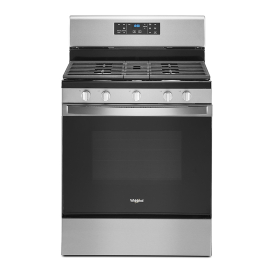
Summary of Contents for Whirlpool WFG525S0JW
- Page 1 FOR SERVICE TECHNICIAN’S USE ONLY W11351206A NOTE: This sheet contains important Technical Service Data. FOR SERVICE TECHNICIAN ONLY Wiring Diagram Do Not Remove Or Destroy DO NOT REMOVE OR DESTROY Quick Connect Plugs Oven Control Wiring Diagram Cooktop Wiring Diagram P1 through P10 for oven controls NOTE: Schematic shows oven door open and elements off.
- Page 2 À L’USAGE DU TECHNICIEN DE MAINTENANCE SEULEMENT W11351206A REMARQUE : Cette fiche contient des données techniques importantes. À L’USAGE DU TECHNICIEN SEULEMENT, Schéma de câblage Ne pas enlever ou détruire NE PAS ENLEVER OU DÉTRUIRE Fiches à connexion rapide Schéma de câblage du module de commande du four Schéma de câblage de la table de cuisson P1 à...
- Page 3 PARA SER USADO ÚNICAMENTE POR TÉCNICOS DE SERVICIO W11351206A NOTA: Esta hoja contiene información de servicio técnico importante. PARA SER USADO ÚNICAMENTE POR TÉCNICOS DE SERVICIO Diagrama de cableado No Quitar Ni Destruir NO QUITAR NI DESTRUIR Enchufes de conexión rápida Diagrama de cableado de control del horno Diagrama de cableado de super cie de cocción P1 a P10 para los controles del horno...


Need help?
Do you have a question about the WFG525S0JW and is the answer not in the manual?
Questions and answers