Sony PBD-V30 Service Manual
Hide thumbs
Also See for PBD-V30:
- Operating instructions manual (84 pages) ,
- Operation instructions manual (84 pages) ,
- Service manual (122 pages)
Table of Contents
Advertisement
Quick Links
SERVICEMANUAL
System
System
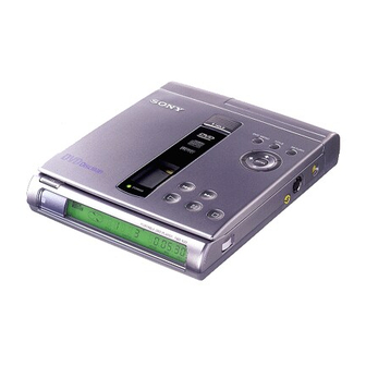
Portable DVD Player
Laser
Semiconductor
laser
Signal format system
NTSC color system, Macrovision
Disc
Compatible discs
. DVD VIDEO
VIDEO CD
l
AUDIO CD (CD-DA)
l
CD-R
l
Disc diameter
12 cm (4)/4 inch), 8 cm (3 inch)
Laser Diode Properties
DVD player
Material
Wavelength
650 nm
Emission
Duration
Continuous
Laser Output
Less than IOOOpW
This output is the value measured at a distance of
200 mm from the objective lens surface on the
Optical Pick-up Block.
CD player
Material
Wavelength
780 nm
Emission
Duration
Continuous
Laser Output
Less than 44.6pW
This output is the value measured at a distance of
200 mm from the objective lens surface on the
Optical Pick-up Block.
9-928-l 08-l 1
SPECIFICATIONS
Audio characteristics
Frequency
response
DVD (PCM):
20 Hz to 44 kHz
CD: 20 Hz to 20 kHz
Signal-to-noise ratio (S/N)
More than 85 dB
High wave distortion rate
Less than 0.02%
Dynamic range
More than 88 dB
Wow and flutter
Less than detected value
W PEAK)
outputs
Jack name Jack type Maximum Load
output
levels
A N
Stereo
1 Vrms
O U T
m i n i j a c k
Optical
-17 dBm
D O L B Y
output
DIGITAL connector
S V I D E O 4.pin
O U T
mini DIN
" P - P
V P - P
PHONES
Stereo
+
PBD-V30
Canadian Model
D I G I T A L A U D I O
General
Power
requirements
Power supply jack
l
DC IN IOV jack accepts the AC-PB I AC power adapter
(supplied), AC 12OV, 60 Hz
Battery pack (not supplied)
l
Power
consumption
AC 120 V, 60 Hz, 0.30 A (max, AC power adapter)
DC 10 V 1,l A (max, DVD VIDEO playback with the
AC power adapter)
Dimensions
(approx.)
Mass (approx.)
Operating temperature
Operating humidity
impedance
Environment
4 7 k R
75 R
Optical
accessories
t e r m i n a t e d
Battery pack
l
Wave length:
AC battery changer
l
660 ""7
DC battery changer
l
75 n sync
Optical
digital
negative
l
7.5 R
Headphones
t e r m i n a t e d
l
Design and specifications are subject to change without
n o t i c e .
PORTABLEDVDPLAYER
US Model
149.6 x 33.5 x 182.3 mm
(6 x 1'1s x 7'/4 inches) (w/h/d)
570 g (1 lb 4 oz) (player only)
5 "C to 35 T (41°F to 95OF)
5% to 80%
Temperature
-20°C to 55°C (4°F
to 13 I "F)
Humidity
15% to 90% Rh
A C - V 7 0 0
D C - V 7 0 0
cable
M D R - 6 0 5 L B
Advertisement
Table of Contents

Related Manuals for Sony PBD-V30


Summary of Contents for Sony PBD-V30
- Page 1 PBD-V30 SERVICEMANUAL US Model Canadian Model D I G I T A L A U D I O SPECIFICATIONS System Audio characteristics General System Portable DVD Player Frequency response Power requirements Laser Semiconductor laser DVD (PCM): 20 Hz to 44 kHz...
- Page 2 LIST ARE CRITICAL TO SAFE OPERATION. REPLACE THESE POUR LA &CURlt~ DE FONCTIONNEMENT. COMPONENTS WITH SONY PARTS WHOSE PART NUMBERS REMPLACER CES COMPOSANTS QlJE PAR DES PI&ES SONY APPEAR AS SHOWN IN THIS MANUAL OR IN SUPPLEMENTS DONT LES NUMeROS SONT DONNEiS PUBLISHED BY SONY.
-
Page 3: Table Of Contents
TABLE OF CONTENTS IC PIN FUNCTION DESCRIPTION SYSTEM CONTROL MICON GENERAL 5-2. A/V CONTROL MICON (MAIN BOARD IC901) ..5-2 DISASSEMBLY 2-l. 2-2. DVD MECHANISM (DVDM-DSO), MAIN BOARD . .2- 1 ..........ELECTRICAL ADJUSTMENT 2-3........ 2-4. 7-l. CHARGE VOLTAGE ADJUSTMENT ...... -
Page 4: Service Note
SERVICE NOTE Do not unpack or install or repair the optical pickup unit KHS-190A series without the grounding processing as shown below. Grounding the human body Be sure to wear a grounding wrist strap (I 0 Q or less) around your wrist to ground the static electricity accumulated in human body. 2 . - Page 5 Sony Corporation Information Technology Company 9-928-l 08-l 1...
- Page 6 Record the serial Using the sub-titles l-23 number in the space provided below. Refer to Welcome! them whenever you call upon your Sony Changing the angles l-24 dealer regarding this product. Preventing accidental pressing of the...
- Page 7 The player cannot . Make sure that the disc play the dwc EXXXX T o p r e v e n t a Please contact your Sony dealer and present the hve dlgts number dlsplayed Example numbers ) (previous/next) VOL (volume) dial (23) buttons (l&24)
- Page 8 OPEN button (14.22) A/V OUT connector (11,50) Rear Panel Opens the disc cover The player Connects to the audlo/vldeo does not work wthout adapter OI battery pack buttons Select the Items or settmgs Accepts the remote control POWER button (14.22) Turns the power on and off the player Front...
- Page 9 Remote SETUP button (53.57) Sets the INITIAL SETUP POWER button (14,22) Turns the power on and off the player. PROGRAM button (36) Plays a disc SUB-TITLE, (SUB-TITLE) ON/OFF buttons (42) the sub-titles on and off, and change the sub-Wle when playmg a DVD VIDEO SHUFFLE button (35) Plays a disc...
- Page 10 This player can play the following discs Logo marks of DVD VIDEOS Logo marks on DVD VIDEO discs or cases are shown as below These marks show avadable contents or functions, DVD VIDEOS some DVD VIDEOS do not have these marks eve” though you may be able to use these funchons For more details of the marks, refer to the mshuchon of the DVD VIDEO &sc VIDEO...
- Page 11 Notes on VIDEO CDs with PBC (Playback Control) Terms for discs functions Title The longest sections of a picture or a music piece on a DVD VIDEO; a movie, enjoy two kinds of playback according to the disc type. etc. for a picture piece on a video software or an album, etc. for a music piece on an audio sofhvare.
- Page 12 About this manual Unpacking Complete the set up using “Getting Started” (pages 10 to 13). For basic operations, see “Playing a DVD VIDEO” (pages 14 to 21) and Check to make sure you have received the following “Playing a CD/VIDEO CD” (pages 22 to 29). items.
- Page 13 Hooking up the system If your TV has an S video input connector Connect the component via the S VIDEO OUT connector the S wdeo cable (not supphed) TV (v&h audlo/vldeo mput connectors) and/or an better picture without a video mput connector Be sure to turn off the power of each component before making the Connecting the AC power adapter connections.
- Page 14 Necessary setup before Playing a DVD VIDEO using the player some nutd setups are necessary for the player connected For detads the menu, see page 53 on using For details on each menu Item, see pages 54 to 56 To connect the player to a normal TV Set “TV ‘WI’!? (PANSCAN)”...
- Page 15 Insert a DVD VIDEO disc Various modes of playback Push gently around the center of the dw unhl It lens buttons CLEAR - ENTER S E A R C H MODE ENTER Close the disc cover, then press D What are title and The player starts playback (Conhnuous Play) chapter? Press...
- Page 16 Using the title menu On a DVD VIDEO, long sections of movies or musk Each of segments you hnd the the pwture (Search) sound these segments 1s called “title VIDEO which contams several titles, you can select the title you want usmg the title menu. If you enter the wrong number Press CLEAR, then the correct number button TITLE...
- Page 17 Using the DVD menu Using the on-screen display What IS angle’, Some DVD VIDEOS allow you to select the disc You can check the operabng status of the player and contents usmg the menu When you play these DVD What is language for VIDEO , you can select the Item, the language for the the TV screen...
- Page 18 Playing a CD/VIDEO CD change according to the on-screen display settmg -When “On-screen display 1” IS selected, the of the current title 1s dlsplayed change accordmg to the on- screen display When “On-screen display 1” 1s selected, the playu~g of the current chapter IS dlsplayed of the current chapter IS dlsplayed Display Information of the on-screen display off mode...
- Page 19 Insert the chsc Various modes of playback After domg Step 5 Push gently around the center of the disc unhi It The menu screen may appear on the TV screen ENTER lens on the VIDEO CD You can play the disc on the menu screen (PBC Playback, Number...
- Page 20 if you enter the wrong number Playing VIDEO CDs with PBC functions Press CLEAR, then the correct number button (PBC Playback -VIDEO CD only) When playmg VIDEO CDs with PBC functions (Ver 0 discs), you can eqoy sunple operations, operations with search functions, PBC Playback allows you to play VIDEO CDs followmg the menu dlsplayed...
- Page 21 Follow operation below enjoy Playback. Using the on-screen display To cancel PBC Playback Refer to the instructions supplied with the disc, as the of a VIDEO CD with PBC You can check the operating status of the player and functions (and play operating...
- Page 22 operations Playing repeatedly (Repeat Play) You can play all the tracks on a disc, a smgle title/ Disc 6’;; Current ~ mode 1 chapter/track, or a speclhc porhon repeatedly To set Current Repeat Play, use the REPEAT or A-B button Playing tune of the current...
- Page 23 When the disc played I n The player repeats Notes Repeating the current track m a Ail the tracks m the The player reverts to In Contmuous Play mode (page 22), you can repeat recorded order only the current track next tune playback All the tracks m random...
- Page 24 Note Using Repeat Play with other play Repeating a specific portion Notes You cannot use Track The player reverts to modes m m Repeat A-B Repeat next tune playback You can use Repeat Play wth Program Play (page 36) You can play a specific portion of a htle/chapter/track starts whenever you, or Shuffle Play (page 35) For example, when you use repeatedly llus...
- Page 25 Creating your own program Playing in random order (Program Play) (Shuffle Play) You can arrange the order of the tracks on the disc and You can have the player “shuffle” tracks and play Notes create your own program. The program can contain The player reverts to them in a random order.
- Page 26 1-21...
- Page 27 Resuming playback from the point where you stopped a disc Notes You may not do on the DVD Resume Play (Resume Play) w m a VIDEO . Dependmg on where you stopped the disc, the player may resume playback from a different The player can store the pomt where you stop The pant where you stopped playback 1s...
- Page 28 Changing the sounds Using the sub-titles q m-m on whxh mulhlmgual sounds are on which sub-htles are recorded, recorded, you can select the language you want whle you can turn the sub-htles on and off and change the playing the DVD VIDEO With mulhplex VIDEO CDs, language of the sub-htles whenever you want whxle playmg the DVD VIDEO you can select the sound from the right or left channel...
- Page 29 Changing the angles Notes Changing the sub-titles The sorts and number Press SUB-TITLE while playmg a DVD VIDEO of languages for sub- on whxh various angles (multi- Each hme you press the button, the mdlcation and the angles) for a scene are recorded, you can change the sub-title change as follows .
- Page 30 Using the rechargeable Preventing accidental battery pack pressing of the buttons You can use headphones (not supphed) and a You can prevent accldental pressmg of the buttons on rechargeable battery pack (not supphed) to enjoy the player mdoors or outdoors the HOLD swtch to ON, the buttons are locked (You can stdl use the remote to operate ) See below for compatible batteries...
- Page 31 Attaching the battery pack Notes Recharging the battery pack . If you turn on the After attachmg the battery pack, connect the AC Open the battery cover until the chck sounds. p l a y e r while chargmg, power adapter, then recharge the battery pack (When chargmg IS s u s p e n d e d p l a y e r not necessary )
- Page 32 Using the audio amplifier Detaching the battery pack Be careful not to drop the battery pack Connecting to the audio amplifier Connect the TV and the amplifier the audio cable (supplied)
- Page 33 Connecting to a digital component such as an N o t e s Note Connecting to a digital component Refer to the Refer to the mstruchons amplifier with a digital input connector, DAT with a built-in Dolby Digital decoder supphed wth the or MD component to be Connect the component wa the KM/DOLBY...
- Page 34 Setting and adjustment Basic settings (INITIAL INITIAL SETUP items Default settmgs are underhned SETUP) MENU N o t e You can make all the necessary settmgs for setup and the language for the DVD menu recorded When you select a that IS not on the DVD VIDEO l a n g u a g e...
- Page 35 DIGITAL OUT Note Switches the outputting methods of audio signals Select setting cannot use the sub- Switches the language for the sub-title recorded on from the PCM/DOLBY DIGITAL connector on the correctly using titles with some DVD the DVD VIDEO. side panel of the player.
- Page 36 Limiting playback by children (Parental Control) ITI m ENTER. As the number of level gets smaller, the Playing some DVD VIDEOS can be limited depending restriction gets more severe. on the age of users. The “Parental Control” function allows you to set a playback limitation level. The display for entering a password appears.
- Page 37 Notes the Parental To return to the normal screen When you play DVD Press SETUP Control Parental Control Press SETUP durmg stop playback To change the country for the Parental cannot be lunlted Control The INITIAL SETUP menu appears on the TV screen Select the country setting m Step 2, then press ENTER Depending on the DVD...
- Page 38 Additional information Precautions On cleanmg the lens and turn table . Do not touch the lens or surroundmg area The enclosed DVD Player 1s and be sure to keep the disc cover closed capable of holdmg a shll wdeo except when mserhng or removmg &scs On sefety On operation Menu xnage...
- Page 39 Replace it with a new . Do not use a disc Sony dealer the video mput connector on the TV The power is not turned on. check that the AC power adapter 1s...
- Page 40 The remote does not function. The disc does not play. Shuffle Play, Program Play, etc. The Parental Control function does not work. cannot performed. Control 1s recorded on remote and the player VIDEO CD, you may not be able to the DVD VIDEO do these funchons country...
- Page 41 Dolby Laboratones The audio data 1s recorded m Dolby battery pack, then consult your Corporation developed This nearest Sony dealer ) technology conforms to 5 l-channel surround. When connecting presence power adapter for a long hme may...
- Page 42 Language code list There are 2 versions of VIDEO CDs Playback Control (PBC) For detazs, see pages 54 and 55 encoded on VIDEO CDs 1 1 You can play only movmg pictures and sounds The language spellings conform to the IS0 639 1988 (E/F) standard (December 1996) By usmg menu screens recorded on VIDEO CDs v&h PBC functions, you Language...
- Page 43 items list INITIAL SETUP Language Code Language Code Language Code 1376 D u t c h 1502 1 5 3 1 Default settmgs are underlined 1532 1379 1503 INITIAL SETUP (page 53) 1534 1393 1505 Slovak ENGLISH DVD MENU 1403 1506 1535 FRENCH...
-
Page 44: Disassembly
SECTION 2 DISASSEMBLY NOTE: Follow the disassembly procedure In the numerical order given 2-1. SUB BOARD screw (2 x 8) board (Remove the soldering) 2-2. DVD MECHANISM (DVDM-DSO), MAIN BOARD Be careful that the splndle the compressed co11 spring c a b l e... -
Page 66: Ic Pin Function Description
SECTION 5... - Page 67 R e m o t e c o n t r o l mput R M C Mode settmg Mode sttm* “H” M D 2 Mode settmg Reset output to AV control L Reel G F S CD GFS mput L O C K CD LOCK mout...
-
Page 68: A/V Control Micon (Main Board Ic901)
5-2. AA/ CONTROL MICON (MAIN BOARD IC901) Name Pm Name N M I NMI ,n,m H Fined XSTBY Data bu\ D I Data bu\ D4 A V C C V R E F NT/PAL AREA0 1331 AVSS v s s ground C C U B E rcw DVD and wdro CD \elec!,on (DVD L. -
Page 69: Self Diagnosis Function
. The disc 1s drty soft cloth (page b3) . The player cannot . Make sure that the dm play the disc To prevent a Please contact your Sony dealer E X X X X the self- are oDtlona1 number d,splayed Exiimple numbers ) - Page 70 the m/croorocessor version No 1 the main microprocessor vers/on the A/V mlcroprocessor version No 1 MAIN board diagnosis SUB board d/agnosls check ( => BIG 1 DRAM check ] => B/t 3 Result d/splay 1 the SUB board check When dlagnosls ends with NG, When error occurs an error InformatIon WI// be displayed...
- Page 71 MD accumulated operating hours /nd/caf/on DVD laser accumulated output hours md/cabon pressed during hours d/splay, the hours data on the d/splay are cleared by reset the /dent/f/cat/on result 1 play back 1 p o s s i b l e Cannot playback the music CD Returns to the mdial state wartmg key Input with the STOP key...
- Page 72 DVD (Dual) Servo Adjustment Set the test d/.sk (HLX-501) DVD MENU key FCS ON (+ TRK OFF, SLED OFF, CL V coarse servo) Traverse automat/c ac$ustment FG, TG automatic aQu.stment the adjustment value) F B/as automat/c adjustment the adjustment value) I DVD _I It I DVD Err Returns to the /n/t/a/ state of wa/Ong...
- Page 73 Set the test disk (HLX-503) FCS ON (+ TRK OFF, SLED OFF, CLV coarse servo) Traverse automat/c adlustment the adlustment value) FG, TG automatic aqustment the aeustment value) F B/as automat/c adjustment Confirm error rate Returns to the /n/t/a/ state walfrng I DVD Err for key input Error Code...
- Page 74 Set the test disk (TGR-21) RETURN key FCS ON (+ TRK OFF, SLED OFF, CL V coarse servo) A/L a@ustment, traverse automat/c ac+ustment FG, TG automat/c ac@stment Returns to the m/t/a/ state warfmg for key input with the STOP key Error Code Durmg the CD servo adjustment adjustment NG...
- Page 75 of the personal computer side The “RS96” directory must be copied to the “Desktop” directory of the PC that 1s used for rewntmg, as an entire directory @Note If the “RS96” directory 15 copied to any locations other than the “Desktop” directory, rewriting ~111 not be performed 2 Preparation of Files When the “RS96”...
- Page 76 Upgrading the Version (Rewntmg the Firmware) Move to the directory where RS96 EXE 1s located, and confirm that the “Size durmg execution” I S m the “Maxlmlzed state” settmg When the prompt “RS232C message appears [SYS] ER Illegal Command’ The first [SYS] means that the machme 1s m the rewrltmg mode of the system control microprocessor The rewriting mode has two modes [SYS] Mode The mode to rewrite the system control microprocessor...
-
Page 77: Electrical Adjustment
SECTION 7 ELECTRICAL ADJUSTMENTS 7-1. CHARGE VOLTAGE ADJUSTMENT When makmg adJustment, refer to 7-4 AdJustment Related Pal ts (MAIN BOARD) Location Diagram. that are necessary for all adjustments of the electllcal clrcult of this machme e l e m e n t 1 RV401 Between TP416 (+) (CN 401) and Instruments required: Measurement point... - Page 78 4. S Video Output DC Level Check (MAIN board) 2. Y Level Adjustment (MAIN board) <Purpose> TV are correct If they are not correct, the TV will not switch to If It 1s not correct, the output Y signal has the incorrect brightness letter box, etc , automatically.
-
Page 79: Repair Parts List
SECTION 8 REPAIR PARTS LIST 8-1. EXPLODED VIEWS N O TE -XX, -X mean standardized pal&, so they may The mechamcal part5 with no reference number The components ldentlfred by mark Aor have some differences from the orlgmal one dotted l i n e with mark A are cntlcal for safety Replace only with part number Item\ marked “*”... -
Page 80: Upper Cabinet Section
8-1-2. UPPER CABINET SECTION supplied R e m a r k s R e m a r k s Ref No Part No Ref No 3-351-377-01 DAMPER 4-900-678-01 KNOB, HOLD 4-900-698-01 4 x 2 5) 4-900-696-01 SEAL(HOLD) SPRING (OPEN),TORSlON 4-900-679-01 4-900-681-11 ORNAMENT,BUTTON 3-336-395-31... -
Page 81: 8-L-3. Dvd Mechanism Section
8-l-3. DVD MECHANISM SECTION Ref No Part No Ref No Part No Remarks A-3250-860-A MECHANISM DVDM-D50 A106 8-820-059-01 OPTICAL PICK-UP KHS-iSOA/JIN 1 0 2 4-210-600-01 SCREW(B1 7) 1 0 7 4-900-703-01 RACK 1 0 3 M902 A - 3 3 0 1 - 4 4 5 - A MOTORASSY,SLED 1 0 4 2-627-529-01 N o t e... - Page 82 8-2. ELECTRICAL PARTS LIST NO TE Due to standaldlzatlon, RESISTORS When lndlcatlng parts by reference number, from the parts All resistors are m ohms please Include the board name METAL metal-film reslctol The components ldentlfled by mark A or METAL OXIDE Metal Oxide-film reFislor dotted l l n e with mark A are crItIcal for safety nonflammable...
- Page 83 Ref No Part No Remarks R e m a r k s Ref No 1-164-357-11 CERAMICCHIP IOOOPF 5% 1-164-156-11 CERAMIC CHIP OluF c 3 7 7 l-165-128-11 CERAMIC CHIP 022uF C 3 7 8 i-162-970-1 CERAMICCHIP OOluF 1-162-953-11 CERAMICCHIP IOOPF 5% c 3 7 9 1-104-851-i TANTAL CHIP...
- Page 84 Ref No Part No R e m a r k s Part No Remarks Ref No C 4 5 2 1-113-500-11 TANTAL CHIP C 6 5 4 CERAMICCHIP c 4 5 3 l-164-346-11 CERAMICCHIP CERAMIC CHIP OOluF c 4 5 4 TANTAL CHIP C 6 5 8 1-164-156-11...
- Page 85 Ref No Part No R e m a r k s Part No R e m a r k s C 7 6 5 CERAMICCHIP <DIODE> l-107-826-11 CERAMICCHIP 1 6 V 1-164-156-11 2 5 V 0 0 0 1 B-719-016-74 DIODE lSS352-TPH3 CERAMICCHIP 1-164-156-11 CERAMIC CHIP OluF...
- Page 86 Ref No Remarks Ref No Part No DIODE 8-759-523-02 IC TC74HC4053AFT(EL) lC652 8-759-701-39 IC NJM2100M(TE2) 8-719-053-31 DIODE CL-170YG-CD-T lC653 8-719-053-31 DIODE CL-170YG-CD-T 8-759-523-03 IC TC74HC4066AFT(EL) 8-759-701-39 IC NJM2100M (TE2) 8-719-053-31 DIODE CL-170YG-CD-T 8-759-701-39 IC NJM2100M (TE2) 8-719-053-31 DIODE CL-170YG-CD-T lC656 IC TC7SlJ04FlJ(TE85R) 8-719-053-31 DIODE CL-170YG-CD-T lC657...
- Page 87 Ref No Part No Remarks INDUCTORCHIP 8-729-029-06 TRANSISTOR Q 7 0 1 INDUCTORCHIP 8-729-029-06 TRANSISTOR 1-411-315-21 INDUCTOR 8-729-029-06 TRANSISTOR 1-414-993-21 INDUCTOR 8-729-029-06 TRANSISTOR Q803 l-414-993-21 INDUCTOR TRANSISTOR 8-729-029-09 TRANSISTOR l-411-775-11 INDUCTOR TRANSISTOR 1-414-993-21 INDUCTOR l-411-939-11 INDUCTOR 8-729-904-86 TRANSISTOR l-412-029-11 INDUCTORCHIP 8-729-029-06 TRANSISTOR l-411-939-11...
- Page 88 Ref No Part No R e m a r k s Remarks Ref No R046 I-216-829-11 METALCHIP 1-216-821-1 METALCHIP R047 1-216-821-1 METALCHIP l-216-833-11 METALCHIP R317 METALCHIP R048 I-216-834-11 METALCHIP R 3 1 8 l-216-821-11 R049 I-216-864-11 METALCHIP l-216-821-11 METALCHIP l-216-821-11 METALCHIP R050 1-216-864-11...
- Page 89 Remarks Remarks 1-218-863-11 RES,CHlP 050% R467 l-216-833-11 METALCHIP R408 l-216-835-11 METALCHIP 1 5 K R468 l-218-895-11 RES,CHIP R409 1-216-821-11 METALCHIP R469 l-218-895-11 1-216-825-11 METALCHIP I-218-895-11 0 50% R 4 7 1 1-218-895-11 R412 1-216-849-11 METALCHIP 220K R472 l-218-863-11 RES,CHIP 050% R 4 7 3 220K R414...
- Page 90 Part No Part No R e m a r k s R e m a r k s R647 I-216-833-11 METALCHIP R726 l-216-823-11 METALCHIP R648 METALCHIP I-216-827-11 METALCHIP R727 R649 1-216-833-11 METALCHIP l-216-864-11 METALCHIP R650 I-216-864-11 METALCHIP R729 l-216-797-11 METALCHIP R 6 5 1 1-216-841-11 METALCHIP...
- Page 91 Ref No Part No Remarks Ref No R e m a r k s R836 l-216-845-11 METALCHIP l-216-821-11 METALCHIP R837 1-216-857-11 METALCHIP l-216-833-11 METALCHIP R838 1-216-857-11 METALCHIP 1-216-864-11 METALCHIP R839 l-216-833-11 METALCHIP 1-216-857-11 METALCHIP R840 METALCHIP l-216-833-11 METALCHIP l-216-864-11 METALCHIP I-216-833-11 METALCHIP R842...
- Page 92 Ref. No. Part No. Part No. R e m a r k s Remarks Ref. No. <VIBRATOR> C 5 5 2 1-113-642-11 TANTAL.CHlP c 5 5 3 CERAMIC CHIP O.luF x 3 0 1 1-767-784-21 VIBRATOR,CRYSTAL27MHz c 5 5 4 1-135-259-11 x 7 0 1 l-767-863-21 VIBRATOR,CERAMlC40MHz...
- Page 93 N o . R ef . Part No. Remarks R e f . Part No. N o . R506 METALCHIP METALCHIP RV552 1-241-391-11 RES, ADJ, METALGLAZE R508 METALCHIP RV553 l-241-391-11 R509 l-216-803-11 METALCHIP RV554 l-241-391-11 l-216-803-11 METAL CHIP l-216-803-11 METAL CHIP <VIBRATOR>...
Need help?
Do you have a question about the PBD-V30 and is the answer not in the manual?
Questions and answers