Advertisement
Quick Links
Installation Instructions
Original Instructions
Back EMF Monitoring Relay Module
Catalog Numbers 440R-S35011, 440R-S35012, 440R-S35013,440R-S35014, 440R-S35015, 440R-S35016
IMPORTANT
Save these instructions for future use.
Description
The Allen-Bradley Guardmaster® MSR55P back EMF modules are
suitable to monitor the standstill of all electric motors that generate a
remanence voltage while coasting to stop.
The MSR55P standstill module is connected to the motor terminals
and measures the induced back EMF voltage. Two redundant measuring
channels are used (L2-L1 and L3-L1). If the back EMF voltage drops to
0V simultaneously in both channels, it indicates standstill and the
output relay is energized.
The voltage threshold that indicates a standstill on the MSR55P
module is adjustable. This standstill allows the unit to work with
different types of motors in various applications. The standstill time T
(time delay between detection and energizing of the relay) is also
adjustable.
The MSR55P standstill module detects a broken wire on the measuring
inputs L1/L2/L3. If a broken wire is detected, the relay outputs go into
safe state (as with running motor).
Features
• Safe standstill detection on three-phase and single-phase motors
• Performance Level is PLe
• Category 4 to EN ISO13849-1: 2008
• Safety integrity level (SIL) 3 to IEC/EN 61508
• SIL Claim Limit (SIL CL) 3 to IEC/EN 62061
• No external sensors necessary
• Standstill detection independent of direction
• Broken wire detection
• Three N.O. redundant voltage-free safety contacts and one
redundant N.C. monitoring contact for up to 250V AC
• Two semiconductor status outputs
• Monitors motor voltage up to 690V AC
• Adjustable voltage setting
•
Adjustable standstill time delay
•
LED indicators for standstill, event of line breakage and
operation voltage
• Suitable for operation with inverters
• Removable screw terminals
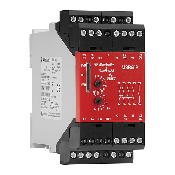
Figure 1 - Overview of Key Features
Three indicators
for status and
diagnostics
DIN Rail Mounting and Removal
s
MSR55P standstill module safety relays mount onto 35 mm (1.4 in.)
DIN rails.
Spacing
MSR55P standstill module safety relays can be mounted directly next to
other MSR and GSR safety relays.
Maintain a space of 50.8 mm (2 in.) above, below, and in front of the
relay for adequate ventilation or provide forced (fan) cooling.
Removable Terminals
MSR55P standstill module safety relays have removable terminals to
ease wiring and replacement.
Removable terminal
blocks
Standstill voltage setting
Standstill time delay setting
1. Insert the tip of a small
screwdriver into the
slot near the terminal
screws.
2. To unlock the terminal
block, rotate the
screwdriver.
Advertisement

Related Manuals for Allen-Bradley Guardmaster 440R-S35011


Summary of Contents for Allen-Bradley Guardmaster 440R-S35011
- Page 1 IMPORTANT Save these instructions for future use. Removable terminal blocks Description The Allen-Bradley Guardmaster® MSR55P back EMF modules are Three indicators Standstill voltage setting suitable to monitor the standstill of all electric motors that generate a for status and Standstill time delay setting remanence voltage while coasting to stop.
- Page 2 Back EMF Monitoring Relay Module Excessive Heat Prevention Relay Face and Terminal Identification For most applications, normal convective cooling keeps the relay within the specified operating range. Verify that the specified temperature range is maintained. Usually, proper spacing of components within an enclosure is sufficient for heat dissipation.
- Page 3 Back EMF Monitoring Relay Module Connect Power Supply Surge Suppressors Power for the MSR55P standstill module safety relay depends on the Because of the potentially high current surges that occur when switching model. The primary power supply is connected to terminals A1 and A2. inductive load devices, such as motor starters and solenoids, the use of An auxiliary (12…30V DC only) supply voltage can be connected to surge suppression is required.
- Page 4 ERR. Rockwell Automation maintains current product environmental information on its website at http://www.rockwellautomation.com/rockwellautomation/about-us/sustainability-ethics/product-environmental-compliance.page. Allen-Bradley, Guardmaster, Rockwell Automation, and Rockwell Software are trademarks of Rockwell Automation, Inc. Trademarks not belonging to Rockwell Automation are property of their respective companies.