
Related Manuals for Equalizer International FA4TM


Summary of Contents for Equalizer International FA4TM
- Page 1 FA4TM & FA9TE FLANGE ALIGNMENT TOOLS Operator Instruction Manual INNOVATION IN ITS MOST FUNCTIONAL FORM...
- Page 2 EQUALIZER法兰错位校正器FA4TM 爱泽工业ize-industries EQUALIZER法兰错位校正器FA4TM套件组件包括: 1 x FA4TM工具 1 x 68N·m(50ft·lb)扭矩扳手 1 x 22mm插座 1 x 棘轮带 1 x 使用说明书 1 x 携带箱 特殊功能 紧凑的轻巧设计8.6kg(19lbs) 4T(40kN)对准力 配有固定带...
-
Page 3: Table Of Contents
PAGE NO. INTRODUCTION SAFETY INFORMATION TECHNICAL DATA FLANGE MISALIGNMENT DETERMINATION PROCEDURE 4.1 LATERAL MISALIGNMENT 4.2 ROTATIONAL (TWIST) MISALIGNMENT FA4TM MECHANICAL FIXED FLANGE AND ROTATIONAL ALIGNMENT TOOL 5.1 KIT COMPONENTS 5.2 HOW THE FA4TM MKII WORKS 9-12 5.3 INSTALLATION AND OPERATION 13-14 5.4 EXAMINATION, MAINTENANCE AND STORAGE... -
Page 4: Introduction
1. INTRODUCTION The Equalizer FA4TM and FA9TE TOOLS are aids for use in normal maintenance and installa- tion procedures, and enable the realignment of misaligned flanges within their respective working capacities. For example, all of the tools can be used to assist in the replacement of ring and other types of flange joint. -
Page 5: Safety Information
These instructions are only to cover the safe operation of THE EQUALIZER FA4TM AND FA9TE FLANGE ALIGNMENT TOOLS, during normal maintenance/installation operations. - Page 6 A CAUTION is used to indicate correct operating or maintenance procedures and practices to prevent damage to, or destruction of equipment or other property. A WARNING indicates a potential danger that requires correct procedures or practices to avoid personal injury. A DANGER is only used when your action or lack of action may cause serious injury or even death.
-
Page 7: Technical Data
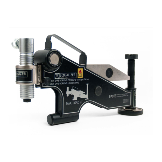
3. TECHNICAL DATA Tool Description Aligning Force Mechanical 4.0 T (40kN) FA4TM Fixed Flange and Rotational Alignment Tool from 50 ft/lbs (67.8 Nm) of torque Hydraulic 9.0 T (90 kN) FA9TE Fixed Flange and Rotational Alignment Tool from 10,000 psi (700 bar) of hydraulic pressure... -
Page 8: Flange Misalignment Determination Procedure
4. FLANGE MISALIGNMENT DETERMINATION PROCEDURE The tool being used must not be attached to a flanged joint prior to the misalignment procedure being carried out. 4.1 LATERAL MISALIGNMENT Loosen and remove every second bolt around the flange , continue with this until misalignment occurs. -
Page 9: Rotational (Twist) Misalignment
4.2 ROTATIONAL (TWIST) MISALIGNMENT If the outer circumference of the flanges are in alignment but the operator is unable to fit the bolt into any two corresponding bolt-holes then rotational misalignment may have occured. In this case the alignment tool can be attached to the most accessible point as misalignment occurs at all bolt-holes to the same degree. -
Page 10: Fa4Tm Mechanical Fixed Flange And Rotational Alignment Tool
Product Code: FA4TMSTD 5.2 HOW THE FA4TM WORKS The FA4TM is secured to the lower of the two flanges by fully inserting the lift hook into the bolt-hole at the point of greatest misalignment. The drop leg is adjusted down to the pipe while the tool is held level in the bolt-hole The wing retaining screw is loosened to allow the wing to be extended out. -
Page 11: Installation And Operation
5.3 INSTALLATION AND OPERATION KNURLED LOCKING HANDLE How to use the torque wrench KNOB Balance the wrench in your left hand and unlock the knurled handle by turning the locking knob anti-clockwise. Newton Scale (N/m) Set the torque amount by turning the knurled handle - see example 40-46 1. - Page 12 POINT OF MAX. Carry out the Flange Misalignment MISALIGNMENT Determination Procedure (see section 4) to determine the points of maximum misalignment. In this example the points of maximum misalignment are at the top and bottom of the joint. POINT OF MAX. MISALIGNMENT Guide the lift hook into the bolt-hole DROP LEG KNOB...
- Page 13 Attach the hook of the strap through the buckle on top of the base plate as shown. Now place the hook of the ratchet mechanism through the opposite side of the buckle as shown. Feed the open end of the strap through the ratchet mechanism as shown.
- Page 14 (67.8 N/m) After replacing all of the bolts (apart from the bolt which will go into the exceeding 50 ft/lbs will bolt-hole in which the FA4TM result in damage to the is located), remove the tool tool by reversing steps 2 -8.
-
Page 15: Examination, Maintenance And Storage
Any missing or damaged items are to be replaced as soon as possible and prior to the tool being used again • Store the FA4TM in a cool dry place and ensure all machined surfaces are greased • Return all items to carry case when not in use •... - Page 16 It is important that the thrust bearing is free from dirt and corrossion and rotates freely. SWIVEL With the use of a penatrating oil such as WD 40 or similar. Spray the oil between the thrust plate and the swivel as shown opposite. THRUST PLATE PENETRATING OIL...
-
Page 17: Parts List
5.5 PARTS LIST Item Part Description Item Part Description 220100-01 Main Body 01 ea Friction Pad 400801-01 01 ea 220200-01 Sliding Arm 01 ea 220500-01 Roller Shaft 02 ea 220700-01 Leg Scrw. Extension 01 ea 901601-01 Spirol Clip 02 ea Leg Screw 220600-01 01 ea... -
Page 18: Weights And Dimensions
5.6 WEIGHTS AND DIMENSIONS WEIGHTS Tool only = 8.6 kg (18.96 lbs) Torque wrench/socket = 0.9 kg (1.98 lbs) Plastic Carry-Case = 2.52 kg (5.55 lbs) GROSS KIT WEIGHT = 11.7 kg (25.8 lbs) DIMENSIONS MINIMUM EXTENSION 367 mm (14.45”) 292 mm (11.49”) 45 mm (1.77”) -
Page 19: Troubleshooting
5.7 TROUBLESHOOTING Problem: The thrust plate is sliding along the circumferance of the opposite flange as the tool is aligning the joint Grit or Dirt on wing, rollers or Ensure the rollers are rotating freely and that there is no restrictions bearings to the rollers on the wing surfaces such as grit or dirt Wing is at full extension... -
Page 20: Application Dimensions
5.8 APPLICATION DIMENSIONS MINIMUM AND MAXIMUM FLANGE SIZES Dimension A: must be between 30 and 133 mm (1.18” and 5.23”) Dimension B: bolt-hole diameter must be 24 mm (0.95”) or greater DIMENSION DIMENSION FLANGE ALIGNMENT TOOLS PAGE 18 OPERATOR INSTRUCTION MANUAL... -
Page 21: Kit Components
6. FA9TE HYDRAULIC FLANGE ALIGNMENT TOOL 6.1 KIT COMPONENTS 1 x FA9TE Tool c/w 6T Hydraulic Cylinder 1 x 10,000 psi (700 bar) Hydraulic Hose, 2m(78.75”) 1 x 10,000 psi (700 bar) HP350S Sealed Hand Pump with Gauge 1 x Instruction Manual 1 x Carry-Case 1 x Ratchet &... -
Page 22: Installation And Operation
POINT OF MAX. 6.3 INSTALLATION AND OPERATION MISALIGNMENT Carry out the Flange Misalignment Determination Procedure (see section 4) to determine the points of maximum misalignment. In this example the points of maximum misalignment are at the top and bottom of the joint. POINT OF MAX. - Page 23 Attach the hook on the strap through the base plate as shown. Now place the hook of the ratchet mechanism through the base on the opposite side as shown. Feed the open end of the strap through the ratchet mechanism as shown.
- Page 24 Connect the hydraulic pump to the hydraulic hose, and the hose to the hydraulic adjusting cylinder. Prime the pump until the joint comes into alignment. Once in alignment the bolts may be inserted and tightened. After replacing all of the bolts (apart from the bolt which will go into the bolt-hole in which the FA9TE is located), remove the tool by...
-
Page 25: Examination, Maintenance And Storage
6.4 EXAMINATION, MAINTENANCE AND STORAGE • On return from each job and before allocation against subsequent work the completeness of the Equalizer FA9TE kit must be established and items examined to ensure that they are serviceable • Any missing or damaged items are to be replaced as soon as possible and prior to the tool being used again •... - Page 26 Remove the circlip using a circlip pliers (not illustrated) Remove the shaft and two bearings. Inspect the bearing housing, shaft, and needle bearings for any sign of damage, dirt or grit. Clean then smear a small amount of grease onto the shaft and into the needle bearings.
-
Page 27: Parts Lists
6.5 PARTS LISTS Item Part Description Item Part Description Main Body 6T H. Cylinder 01 ea 230100-01 01 ea 903101-01 Wing Arm Spirol Clip 02 ea 230200-01 01 ea 901601-01 Plastic Insert 03 ea Logo For Wing 01 ea 230202-01 070233-01 M6 Release Knob 03 ea... - Page 28 HP350S HAND PUMP ITEM PART No. DESCRIPTION QUANTITY ITEM PART No. DESCRIPTION QUANTITY 710101-01 PUMP HOUSING 715800-01 SERVICE KIT H: SERVICE KIT A: 715100-01 - CHECK BALL - OIL FILTER - SPRING END CAP - O-RING - SPRING - RESERVOIR BLADDER - SPRING - REFILLING PLUG - O-RING...
-
Page 29: Weights And Dimensions
6.6 WEIGHTS AND DIMENSIONS WEIGHTS Tool with Hydraulic Cylinder = 15.5 kg (34.1 lbs) HP350S Hand Pump = 4.5 kg (9.9 lbs) Hydralic Hose = 1.0 kg (2.2 lbs) Plastic Carry-Case = 7.5 kg (16.5 lbs) GROSS KIT WEIGHT = 28.5 kg (62.8 lbs) OVERALL DIMENSIONS MINIMUM EXTENSION MAXIMUM EXTENSION... -
Page 30: Troubleshooting
6.7 TROUBLESHOOTING Problem: The tool is advancing but does not reach full pressure Air could be present in Use the airlock removal the hydraulic system procedure as follows: Connect the hand pump to the tool with the hydraulic hose RESERVOIR Close the release valve on the pump, and prime the pump... - Page 31 Problem: The friction pad is sliding in the circumference of the opposite flange as the tool is aligning the joint Grit or dirt on wing, rollers or Ensure the rollers are rotating freely and that there is no restriction to ...
-
Page 32: Range Of Application
6.8 RANGE OF APPLICATION MINIMUM AND MAXIMUM FLANGE SIZES Dimension A: must be between 93 and 228 mm (3.75” and 9”) Dimension B: bolt-hole diameter must be 31.5 mm (1.25”) or greater DIMENSION DIMENSION FLANGE ALIGNMENT TOOLS PAGE 30 OPERATOR INSTRUCTION MANUAL... -
Page 33: Bs10, Api6Bx And Api6B Flange Tables
FLANGE ALIGNMENT TOOLS PAGE 31 OPERATOR INSTRUCTION MANUAL... -
Page 34: Asme B16.5, B16.47 And Din Weld Neck Flange Tables
FLANGE ALIGNMENT TOOLS PAGE 32 OPERATOR INSTRUCTION MANUAL... -
Page 35: Spo Flange Table
FLANGE ALIGNMENT TOOLS PAGE 33 OPERATOR INSTRUCTION MANUAL...
Need help?
Do you have a question about the FA4TM and is the answer not in the manual?
Questions and answers