Advertisement
Thermal Disinfection Valve
Installation & Operating Instructions
AC17-080
Step 1 : Safety First
These instructions relate to the use of the Thermal
Disinfection Valve only, any external or 'add-on' parts will be
supplied with separate instructions.
You must read these instructions thoroughly before attempting
to install this product.
Please note; Once returned to normal operation, be sure
to run water for 10 seconds to purge out hot water in cold
pipework.
IMPORTANT : Please read these instructions
carefully and follow each stage in order!
Dart Valley Systems | Kemmings Close | Long Road | Paignton | Devon | TQ4 7TW | UK
t +44 (0)1803 529 021 | f +44(0)1803 559 016 | www.dartvalley.co.uk | techsupport@dartvalley.co.uk
Step 2 : Parts
A typical system will comprise of the parts* below:
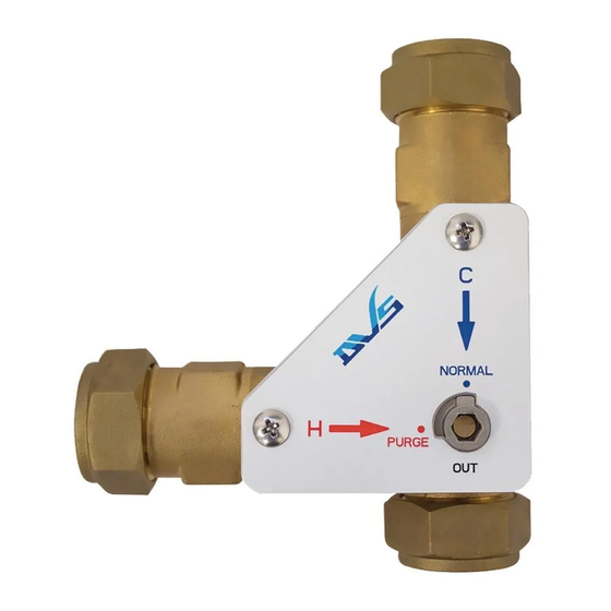
1x AC17-080
1x Label
Step 3 : Optional parts
Optional system parts will comprise of the parts* below:
UC00-070 - Reducing Kit
1x Allen key
Instruction Manual x1
Advertisement
Table of Contents

Related Manuals for Franke DVS AC17-080


Summary of Contents for Franke DVS AC17-080
- Page 1 Thermal Disinfection Valve Installation & Operating Instructions AC17-080 Step 1 : Safety First Step 2 : Parts These instructions relate to the use of the Thermal A typical system will comprise of the parts* below: Disinfection Valve only, any external or ‘add-on’ parts will be supplied with separate instructions.
- Page 2 Disinfection Valve (TDV) Step 4 : Typical Installation THERMAL PURGE OPERATION The Thermal Disinfection Valve is typically directly plumbed into the water supply, when a thermal purge is required the As short as practicable valve can be switched between “NORMAL” and “PURGE” operation via quarter turn.
Need help?
Do you have a question about the DVS AC17-080 and is the answer not in the manual?
Questions and answers