Advertisement
Quick Links
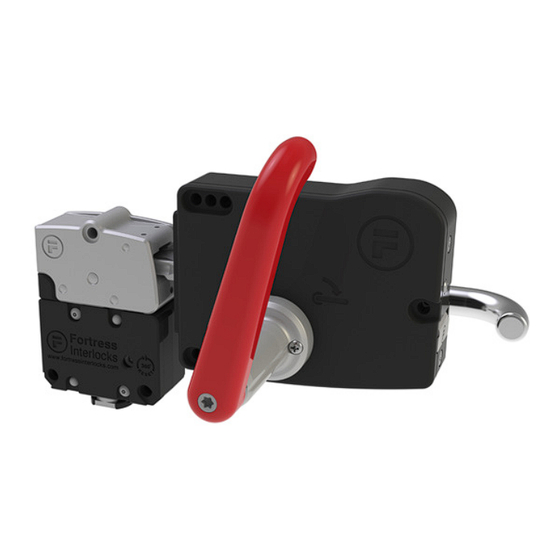
Operating Instructions: Single Action Escape Release
Head & Handle
Description
For secure head retention in all applications the top M8 head fixings must be used.
Fortress provides a single action escape release function from inside a guarded
area through the use of a head and handle application. This unit may be installed
in left or right orientation to hinged doors. The tongue incorporates a self-aligning
feature to cater for misalignment on guards. Simply turning the red handle will open
a locked guard from the inside and open the safety contacts. Releasing versions of
other modules are the type that MUST be used in conjunction with this module.
• Intuitive single action escape release handle.
• Escape release activation releases tongue and opens safety contacts.
• Handle includes Lock-Out for 4 padlocks of 8mm diameter.
• 10kN retention force.
• Stainless steel tongue is ideal for fast and frequent access.
• 2 mounting position at 180° increments allowing on site handing change
possible.
• Misalignment tolerance of +/- 10mm with +/- 4° angular misalignment.
• Security tool reset after escape release actuation or auto reset function available.
• Head can be fitted with lock-out device for additional lockout capability.
NOTICE!
If, as a result of risk assessment, it cannot be discounted that persons can be enclosed within a danger zone, the guard locks
with additional removable keys (safety keys) must be used or comparable measures must be taken - GS ET 19.
Options & Ordering Information
Description
proHead
Security Tool Reset Escape Release Head
Security Tool Reset Escape Release Head c/w Drop Down Lock-Out
Automatic Reset Escape Release Head
Automatic Reset Escape Release Head c/w Drop Down Lock-Out
proHandle
Escape Release Handle
Escape Release Handle
Escape Release Handle - Allowing Closing of Door From Inside
Escape Release Handle - Allowing Closing of Door From Inside
Important:
This product is designed for use according to the installation and operating instructions enclosed. It must be installed by
a competent and qualified personnel who have read and understood the whole of this document prior to commencing
installation. If the equipment is used in a manner not specified by the manufacturer the protection provided by the equipment
may be impaired. Any modification to or deviation from these instructions invalidates all warranties.
Fortress Interlocks Ltd accepts no liability whatsoever for any situation arising from misuse or mis-application of this product.
Note: The availability of spare Actuators and Keys makes it possible to easily bypass the safety devices and, for this reason,
the security of any spare Actuators and Keys must be effectively monitored.
DO NOT LEAVE OVERRIDE/RESET KEY IN PLACE!
Always keep in a secure place, under management control, as it allows access to areas that may have a residual
hazard, and may result in incorrect operation of some devices.
Safety switches (such as a STOP or LOK) must be fitted in conjunction with this unit to monitor when the Internal
Escape Release has been activated. When lock adaptors are also used it is not possible to change outside from a
STOP to a LOK (and vice versa) without other changes to the locks - seek advice from Fortress.
BEWARE OF INTENTIONAL MISUSE CAUSED BY OPERATORS WANTING TO BYPASS SAFETY SYSTEMS. THE
INSTALLER SHOULD ASSESS THE RISKS AND MITIGATE AGAINST THEM.
IF YOU HAVE ANY QUESTIONS OR QUERIES OF ANY NATURE WHATSOEVER PLEASE CONTACT THE SUPPLIER
WHO WILL BE PLEASED TO ADVISE AND ASSIST.
Part No.
I6
I7
A6
A7
EI2
EI4
EJ2
EJ4
1
Gard
Handling
Left / Right
Left / Right
Left / Right
Left / Right
Left
Right
Left
Right
Advertisement

Related Manuals for Halma Fortress amGardpro

Summary of Contents for Halma Fortress amGardpro
- Page 1 Gard Operating Instructions: Single Action Escape Release Head & Handle Description For secure head retention in all applications the top M8 head fixings must be used. Fortress provides a single action escape release function from inside a guarded area through the use of a head and handle application. This unit may be installed in left or right orientation to hinged doors.
- Page 2 Operating Instructions: Single Action Escape Release Head & Handle amGardpro Escape Release Head & Handle Technical Specification Housing Zinc Alloy to BSEN12844 & Stainless Steel to BS3146 Materials Internals Stainless Steel to BS3146 Paint Finish Housing Gloss powder coat on Passivated Zinc Alloy - Black Holding Force, F 10kN Operating Force...
- Page 3 ARE IN mm UNLESS www.fortressinterlocks.com 1.00 1 OF 6 DISCLOSED TO ANY 3rd PARTY WITHOUT SPECIFIC, WRITTEN APPROVAL. OTHERWISE STATED SCALE: SHEET: Halma company DROPDOWN LOCKOUT OPEN DROPDOWN LOCKOUT CLOSED SD-00018 AMGARD PRO I7 & A7 ESCAPE RELEASE HEAD DIMENSIONS DWG NO: FORTRESS 25-02-2020 THE COPYRIGHT OF THIS DRAWING BELONGS TO FORTRESS INTERLOCKS Ltd.
- Page 4 ARE IN mm UNLESS 0.40 4 OF 6 www.fortressinterlocks.com DISCLOSED TO ANY 3rd PARTY WITHOUT SPECIFIC, WRITTEN APPROVAL. OTHERWISE STATED SCALE: SHEET: Halma company SD-00018 AMGARD PRO ESCAPE RELEASE HEAD AND HANDLE DWG NO: FORTRESS 25-02-2020 ORIGINAL SIZE THE COPYRIGHT OF THIS DRAWING BELONGS TO FORTRESS INTERLOCKS Ltd.
- Page 6 Operating Instructions: Single Action Escape Release Head & Handle Tools and Fixings Required Ø8.2mm Drill Ø6.2mm Drill 3 x M8 screws (Rear fixing) 3 x M8 Washers 3 x M6 Screws 3 x M6 Nuts (Optional) 3 x M6 Washers Mounting (Escape Release Head) 1.
- Page 7 Operating Instructions: Single Action Escape Release Head & Handle 3. Position the handle so the adjustable tongue is in central position vertically position to compensate for movement of guarding in either direction overtime. Note: The distance between the interlock and handle mounting points should within the specified range to allow the tongue to fully insert into the interlock mechanism while ensuring the door can be opened and closed without the handle body making contact with the unit head.
- Page 8 Operating Instructions: Single Action Escape Release Head & Handle Plate or Guards greater than 40mm thick (e.g. noise attenuating door) This will require an EI / EJ Handle with an extended red escape release handle or an extension kit to be added to a standard EI handle.
-
Page 9: Service And Inspection
Operating Instructions: Single Action Escape Release Head & Handle Service and Inspection Regular inspection of the following is necessary to ensure trouble-free, lasting operation: • Correct operating function • Secure mounting of components • Debris and wear • WD40 lubricant or equivalent, should be applied to each mechanical element every 10,000 operations, or sooner, to ensure smooth product operation and function.
Need help?
Do you have a question about the Fortress amGardpro and is the answer not in the manual?
Questions and answers