Advertisement
Quick Links
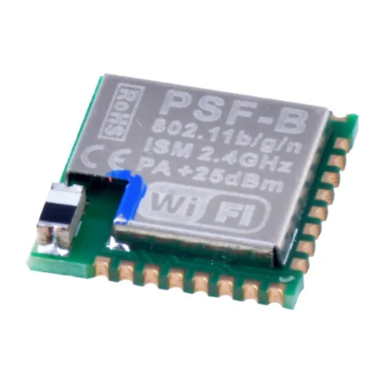
PSF-B04 Application Guide
1.Product Introduction
PSF-B04 is a 4-channel ultra-low-power Wi-Fi switch module based on ESP8285. It's
specially designed for mobile devices and Internet of Things applications with the most
competitive package size and ultra-low energy consumption technology in the industry.
Connecting users' devices to the Wi-Fi wireless network for remote or local area network
communication to achieve networking. This module can be used as a switch control for 4
household appliances. Either it can be controlled by the device button, or remotely
controlled by connecting to APP (eWeLink).
PSF-B04 has various packaging methods, and the antenna supports ceramic
antennas. It can be widely used in smart grid, smart transportation, smart home,
handheld devices, industrial control and other fields.
Product Features:
•
Built-in 32bit MCU, and can double as an application processor
•
Support wireless 802.11 b/g/n standard
•
Wi-Fi @2.4 GHz, support WPA/WPA2 security mode
•
+20.5dBm maximum outputpower in 802.11b mode
•
Support devicebutton control
•
Support timer schedule
•
Support Wi-Fi remote control
•
Support compatible pairing mode /quickpairing mode
•
Support OTA upgrade
2.Electrical Characteristics
2.1 Rated parameters
Conditions: VDD=3.3V±10% , GND=0V; test at room temperature 25°C.
Type
Model
Main chip
Hardware interface
Operating Voltage
Parameters
PSF-B04
ESP8285
UART, GPIO
2.7V~3.6V
Advertisement

Related Manuals for Sonoff PSF-B Series


Summary of Contents for Sonoff PSF-B Series
- Page 1 PSF-B04 Application Guide 1.Product Introduction PSF-B04 is a 4-channel ultra-low-power Wi-Fi switch module based on ESP8285. It’s specially designed for mobile devices and Internet of Things applications with the most competitive package size and ultra-low energy consumption technology in the industry. Connecting users’...
- Page 2 GPIO drive Max: 12mA capability Average current: ≈80mA , Maximum working current: Working current 210mAStandby: <200uA Operating 0℃~45℃ temperature Storage condition Temperature: -10℃~75℃ , Relative humidity: 20%RH~80%RH Wireless network STA/AP/STA+AP type Encryption WEP/WPA-PSK/WPA2-PSK mechanism Encryption type WEP64/WEP128/TKIP/AES Firmware upgrade OTA remote upgrade 2.2 Wi-Fi parameters Conditions: VDD=3.3V±10% , GND=0V ;...
- Page 3 802.11b: 20±2dBm (@11Mbps) 802.11g: 17±2dBm (@54Mbps) Transmit power 802.11n: 14±2dBm (@HT 20, MCS 7) Receiving 802.11b: -91 dBm (@11 Mbps, CCK) 802.11g: -75 dBm (@54Mbps, sensitivity OFDM) 802.11n: -72 dBm (MCS7) Antenna type Ceramic patch antenna 3.Module Type and Pin Definition 3.1 Module type PSF-B04 top view 3.2 Sequence of pin arrangement...
- Page 4 Bottom view of module pins:...
- Page 5 3.3. Pin definition Pin definition and function description Name Features Wi-Fi Antenna Note: PSF-B04 cannot be used ADC interface, input range: 0-1V Chip enable terminal high level: valid; low level: closed.Note: An external pull-up resistor of 1~10K, connect a 100nF capacitor to the ground.
- Page 6 The relay switch for the first channel: active high, power-on default low level. Note: As a switch button, there will be a period of high level at GPIO12 the moment of power-on, which requires a pull-down (1~4.7K) resistor to ground. Wi-Fi status indicator light, connect LED in series with current limiting STATUS resistor to 3V3...
-
Page 7: Function Description
GPIO7 GPIO8 The relay switch for the second channel, active high, power-on default GPIO5 low level. Used to program flash UART_RX Used to program flash UART_TX Power supply External reset signal: active at low level, externally need to pull up a 10K resistor to 3.3V, and connect a 100nF capacitor to ground. - Page 8 5. Timer: including single, count down, repeat, and loop timer, see details in 4.5. 6. Power-on status configuration: The power-on switch status can be configured on or off through the APP, and the default power-on status is off. 4.2. Wi-Fi status indicator light description The flashing mode of the Wi-Fi status light on the device represents the its current network working status.
- Page 9 3. No Server: The device has been connected to the router, but it cannot connect to the server (also known as”cannot access the Internet”). 4. Unregistered: The device has not been bound to account. The device needs to be bound to the eWeLink account to connect to the cloud server.
- Page 10 When the connection/acquisition fails in the above steps, there are corresponding back- off strategies and reconnection mechanisms to ensure that the device is stable and keep online. 3. Upgrade The module connects to the upgrade server, downloads and updates to the latest version of the firmware to realizes the online upgrade of the device.
- Page 11 Input reflection PA output peak valuepower when at 15.5 16.5 17.5 72.2Mbps PA output peak value power in 802.11b 19.5 20.5 21.5 mode 5.1 Sensitivity Description Typical value Unit mA CCK 1Mbps CCK 11Mbps 6Mbps(1/2BPSK) 54 Mbps (3/4 64-QAM) HT20, MCS7 (65Mbps,72.2Mbps) 5.2 Adjacent frequency suppression Description Typical value...
-
Page 12: Pcb Design
OFDM, 54Mbps HT20, MCS0 HT20, MCS7 Note: 1. 2Mbps is measured in the 802.11n mode, the MCS =7, the GI = 200uS. 2. Up to + 21.5dBm output powerin 11b mode. 6.PCB Design Precautions for PCB layout and module layout: 1. - Page 13 4. Place the module’s power supply (VCC) pin capacitance and other module pin capacitances, resistors as close as possible to the module pins, and the tracepath should be short. 7.Packaging Information Package size diagram: Share this:...
Need help?
Do you have a question about the PSF-B Series and is the answer not in the manual?
Questions and answers