
Related Manuals for Facilities Resource Group Standard Series

Summary of Contents for Facilities Resource Group Standard Series
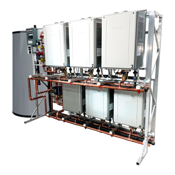
- Page 1 TTS (Total Tankless Solution) Commercial Water Heating System (Standard Series) Installation Manual TTS-S6 6 Water Heater System TTS-S-IM V2 09.22...
-
Page 2: Table Of Contents
Table of Contents Description....................................2 Before Installation .................................. 3 Venting the TTS Rack System ..............................9 Clearances ..................................... 19 TTS-S Commercial Water Heating System Parts Number & Main Components ..............22 TTS-S Specifications (System Dimensions) .......................... 23 TTS-S Specifications (Parameters) ............................25 Securing Floor Standing TTS-S Models .......................... -
Page 3: Before Installation
FRG’s TTS Series provides the most complete commercial water heater solution in the market. This tankless water heating system provides up to 1.2 mil-lion BTU/h in the smallest footprint while having the advantage of redundancy and equalizing heating performance. The TTS-S provides a time and labor-saving solution when installing multiple Noritz tankless water heaters. OPC (One Point of Connection) Water, Power, Gas, Venting &... - Page 4 TTS-S-IM V2 09.22...
- Page 5 Uncrating the TTS [Moving the TTS Racks] The rack is designed to be accessible from either of 2 directions. Refer to the following diagram for accessibility options for moving the rack system. Orientation Pallet Jack Forklift Front/Back Accessible Accessible Sides Not Accessible Accessible Note Before unpacking the rack, verify that the product is physically free of damage...
- Page 6 TTS-S2MINI, 3 Side View TTS-S4MINI, 5 Side View TTS-S6 Side View [Unpacking the TTS Rack] TTS-S-IM V2 09.22...
- Page 7 1. Remove six (6) screws to remove the top panel of the TTS rack 2. Remove six (6) screws to remove the front panel 3. Remove four (4) screws to remove the left top retaining blocks 4. Remove four (4) screws to remove the left top retaining blocks 5.
- Page 8 (View from Top) 11. Slide the TTS rack forward to remove from crate TTS-S-IM V2 09.22...
- Page 9 NORITZ America Corporation Technical Bulletin TB081122 – Additional Polypropylene Venting Options This technical bulletin is to inform Noritz customers about changes to our venting options and allowances for the following tankless water heater products: EZ98DV (GQ-C2860WX-FF US) EZ111DV (GQ-C3260WX-FF US) NRCR92DV (GQ-C2660WXQ-FF US) NRCR111DV (GQ-C3260WXQ-FF US) NCC199CDV (GQ-C3260WZ-FF US)
-
Page 10: Venting The Tts Rack System
Venting the TTS Rack System • Only vent materials approved for use with Category IV appliances shall be used. • Under normal conditions, this water heating system will not produce exhaust flue temperatures in excess of 149 °F (65 °C) and schedule 40 PVC pipe may be used as the vent material. If the system set temperature is 160 °F (70 °C) or higher and there is a return line to the system from either a recirculation pump or a storage tank, schedule 40/80 CPVC or PP must be used. - Page 11 • Under normal conditions, this appliance will not produce an exhaust flue temperature in excess of 149°F (65°C) and schedule 40 PVC pipe may be used as the vent material. If the water heater set temperature is 160°F (70°C) or higher and there is a return line to the water heater from either a recirculation pump or a combination space heating system, use schedule 40/80 CPVC or PP •...
- Page 12 • The maximum vent length when using 3 in. (75mm) pipe is 150 ft. • The maximum lengths are reduced by the number elbows used, as shown in the following table: Acceptable Termination Types The vent for each water heater may be terminated with any of the specialty terminations listed in the table below.
- Page 13 Exhaust Exhaust Exhaust Intake Intake Intake Interior View Side View ≥ 3 in MIN For both Exhaust & Intake When using Concentric Terminations Using the PVC-2CT or PVC-3CT • Multiple concentric terminations clearances should be grouped in pairs. One set shall be terminated a maximum 4 in (100 mm) apart, with the next pair maintaining a minimum of 24 in (0.6 m) spacing from the next pair.
- Page 14 Using the PVC-2LPT, PVC-3LPT, or PVC-UCVK • Multiple concentric terminations must be a minimum of 12” (0.3m) between terminations • Do not vertically align multiple terminations. Clearance Requirements Between Multiple Terminations (Vertical) TTS-S-IM V2 09.22...
- Page 15 When Using 90 Elbows or Tee Fittings • Maintain at least 3 ft (0.9m) distance between the intake and exhaust of the appliance • Maintain at least 1 ft (0.3m) distance between the exhausts of multiple units. When Using Concentric Terminations TTS-S-IM V2 09.22...
- Page 16 • For terminations at un-equal heights, maintain 24” (600 mm) minimum clearance. • For terminations at equal heights, maintain a 24” (600 mm) minimum clearance. Note: Drawings shown with optional PRC-1 accessory Common Venting the NCC199CDV TTS-S-IM V2 09.22...
- Page 17 The NCC199CDV is tested and approved to be common vented up to a maximum of 6 units on a single exhaust system. For full installation instruction on common venting the TTS-S, refer to the Common Vent Installation Manual. Guidelines for Common Venting •...
- Page 18 Determining the Size of the Common Vent • The minimum equivalent vent length is 3 ft. • Follow the table below for determining the maximum vent length and diameter of the common vent installation. • For complete instructions on determining the appropriate sizing of the common vent installation, refer to the Common Vent Installation Manual or contact Noritz technical support at (866) 766-7489.
- Page 19 Table 2: Equivalent Length of each Elbow (ft) Diameter of Elbow 3” 4” 6” 8” Length Total Equivalent Vent Length (TL) = Straight Vent Length (L) + Equivalent Length of Elbows • TL shall be less than the values listed in the Table 1 above. •...
-
Page 20: Clearances
Clearances Install the rack system so that the clearances shown below are followed. Clearance Requirements for Both Combustibles and Non-Combustibles Indoor Outdoor (with vent cap) Top of Heater 12" (300mm) 36" (900mm) Left Side of Rack 3" (75mm) 3" (75mm) Right Side of Rack 3"... - Page 21 Recommended Clearance for Service and Maintenance when Common Venting When common venting the TTS system, the following clearances are recommended in order to facilitate service and repair of the TTS system. [Inline Configurations – PVC or CPVC] [Inline Configurations – using PP TTS-S-IM V2 09.22...
- Page 22 TTS-S-IM V2 09.22...
-
Page 23: Tts-S Commercial Water Heating System Parts Number & Main Components
* The clearance requirements from vent terminations to building openings chart above apply to SV converted units. TTS-S Commercial Water Heating System Parts Number & Main Components TTS-S-IM V2 09.22... -
Page 24: Tts-S Specifications (System Dimensions)
TTS (Standard Series) Commercial Water Heating System Model Number Rack Type Configuration Illustration 2 Unit, Total Tankless Solution TTS-S2MINI-LP Standard Series, LP (399,800 BTU/hr) 2 Unit, Total Tankless Solution TTS-S2MINI-NG Standard Series, NG (399,800 BTU/hr) 3 Unit, Total Tankless Solution... - Page 25 Length (A) Depth (B) Height (C) 35” 31.5" 80” TTS-S2MINI: Total Tankless Solution – Standard Series (399,800 BTU/hr) TTS-S3: Total Tankless Solution – Standard Series (599,700 BTU/hr) 52.25" 31.5" 80” 56.75” 31.5" 80” TTS-S4MINI: Total Tankless Solution – Standard Series (799,600 BTU/hr) TTS-S5: Total Tankless Solution –...
-
Page 26: Tts-S Specifications (Parameters)
TTS-S Specifications (Parameters) TTS-S-IM V2 09.22... -
Page 27: Securing Floor Standing Tts-S Models
Securing Floor Standing TTS-S Models • All mechanical components shall be anchored and installed in accordance with national and local codes including anchorage to building structures. • For minimum concrete thickness, refer to local codes or consult with a licensed structural engineer regarding the use of appropriate expansion anchors capable of supporting the TTS weight. -
Page 28: Freeze Prevention / Insulation
Freeze Prevention / Insulation • In normal operation, freezing is prevented within the device automatically unless the outside temperature without wind is below -30°F (-35°C) for indoor installation or -4°F (-20°C) for outdoor installations. • For models installed in an area where the outside temperature can approach freezing conditions of -30°F (-35°C) or outdoor -4°F (-20°C) or below, then additional protection measures must be used. -
Page 29: Condensate Drain To Floor Or With Pump
Condensate Drain to Floor or with Pump • Each TTS unit comes with a condensate drain pre-piped which must be properly drained to ensure proper operation of this appliance. • The pH level of the condensate is approximately 2-3. An external neutralizer must be installed on the drain piping prior to disposal when required by local code or when the condensate could cause damage. - Page 30 • If the water heater has been out of use for a long period of time, make sure that you fill the condensate trap with water. This is to prevent dangerous exhaust gases from entering the building. Failure to fill the condensate trap could result in severe personal injury or death. * Do not use the condensate water, discharged from the drain pipe, for drinking purposes.
-
Page 31: Water Treatment
Water Treatment If the TTS-S will be installed in an application where the supply water is hard, the water must be treated with a water softener. Refer to the below tables for suggested treatment and maintenance measures to be taken based on the water hardness level. -
Page 32: Electrical Wiring
Electrical wiring The power connection of each unit on the TTS has been completed at factory. These units are powered from the break panel located on the TTS Rack. The Electrical Contractor will need to do the following: • Install one circuit - 30A, 208/240V-1Ph-3Wire w/Ground to the panel on the TTS Rack in accordance with all National, State and Local Codes Power Connection inside Break Panel: TTS-S-IM V2 09.22... -
Page 33: Remote Controller
Remote Controller • The TTS-S comes with a remote controller (RC-9018M) that must be installed into unit #1. Refer to the schematic on pg. 58 of this manual for instructions on locating unit #1. • Refer to directions below or pg. 45 of the Water Heater Installation Manual for description on installing the remote controller •... -
Page 34: Multi System Controller
• For additional information, refer to (SC-401-6M) Installation Manual for information such as remote initial setup (pg. 9), recirculation pump timer setup (pg. 13), system check button (pg. 15), maintenace monitors and additional settings (pg. 16). *The remote controller is not resistant to water, steam, chemcials, or UV rays. Store the remote in a location where it will not be exposed to these conditions. - Page 35 TTS-S-IM V2 09.22...
- Page 36 • The system controller is installed inside the rightmost unit denoted by a #1 sticker located on the front cover of the unit. • Each unit will have a numbered sticker on the front cover, ordered in a clockwise direction (Refer to diagram below).
- Page 37 8. Control functions 8.2.1 Light fields indicating the pump setting The pump has optional performance settings 8.1 Elements on the control panel which you can select with the push-button. See fig. 9. The pump setting is indicated by light fields in the display.
- Page 38 8.5 Pump control Manual summer mode In manual summer mode, the pump is stopped See section 8.6 Pump performance and to save energy and only the electronics are operating mode selection. running. To avoid lime deposit that could block AUTO , underfloor heating and two-pipe the pump, the pump is started every 24 hours for ADAPT...
- Page 39 8.6 Pump performance and operating mode selection The hydraulic performance shown is without check valve. AUTO ADAPT Operating range (maximum to minimum) Pos. Description • Push-button for selection of pump setting • Every time you press the push-button, the circulator setting is changed. High constant speed •...
- Page 40 9. Fault finding the product DANGER WARNING Electric shock Pressurized system Death or serious personal injury. Death or serious personal injury. - Switch off the power supply before - Before dismantling the pump, drain starting any work on the product. the system or close the isolating Make sure that the power supply valve on either side of the pump...
- Page 41 Insufficient Light field is on. The pump Increase the pump speed or heat performance is set constant pressure. too low. The thermostat is set Check to see if the circulator is in too low or is not the proper operating mode. working.
- Page 42 10. Technical data In domestic hot water systems, keep the liquid temperature below 149 °F 10.1 Operating conditions (65 °C) to eliminate the risk of lime precipitation. Supply voltage 1 x 115 V, + 10 %/- 10 %, 60 Hz. Glycol Maximum glycol concentrations with clean Motor protection...
- Page 43 11. Disposing of the product This product or parts of it must be disposed of in an environmentally sound way: 1. Use the public or private waste collection service. 2. If this is not possible, contact the nearest Grundfos company or service workshop. Subject to alterations.
- Page 44 Digital Controller Functions Overview TTS-S-IM V2 09.22...
- Page 45 TTS-S-IM V2 09.22...
- Page 46 TTS-S-IM V2 09.22...
- Page 47 TTS-S-IM V2 09.22...
- Page 48 TTS-S-IM V2 09.22...
- Page 49 TTS-S-IM V2 09.22...
- Page 50 TTS-S-IM V2 09.22...
- Page 51 TTS-S-IM V2 09.22...
- Page 52 TTS-S-IM V2 09.22...
- Page 53 TTS-S-IM V2 09.22...
- Page 54 Timer Switch Operation TTS-S-IM V2 09.22...
-
Page 55: Final Checklist
(except items with designated conditional answers), installation is not complete. Review the appropriate sections to complete the installation. If you have any questions or need assistance with the installation, contact Facilities Resource Group at 877-554-0004. Before Installation... - Page 56 Condensate drain is discharging condensate (This may require operating water heaters for upwards of 15 minutes) Condensate is flowing freely Condensate line is free of leaks Condensate is disposed of in accordance with local building codes Electrical Electricity supplied is single phase, 120VAC, 60 Hz Post Installation Control module (RC-9018M) is mounted in a clean, dry location (RC-9018M is not waterproof or UV rated)
-
Page 57: Trial Operation
Trial Operation The installer should test operate the unit, followed by explaining to the customer how to use the unit, and give the owner this manual before leaving the installation site. Preparation steps. 1. Confirm the condensate trap is filled with approx. 10 oz. (280 mL) of water inside the exhaust (indoor installations). - Page 58 • If the water heater does not operate normally, refer to “Troubleshooting” in the Operation Manual. After the trial operation, clean the filter in the cold water inlet. • Use the remote controller to see the status of how many units are igniting. Shutdown Steps.
-
Page 59: Warranty For Tankless Units & Tts System Components
Warranty for Tankless Units & TTS System Components Warranty Registration Required * Start Up Sheet Required** Warranty Period Period of Coverage (Date of Installation or 30 Days After Purchase) Labor Parts Heat Exchanger Tankless Water Heater* 1 year 5 years 10 years TTS-S Series** 1 year... - Page 60 TTS-S-IM V2 09.22...
- Page 61 TTS-S-IM V2 09.22...
Need help?
Do you have a question about the Standard Series and is the answer not in the manual?
Questions and answers