Table of Contents
Advertisement
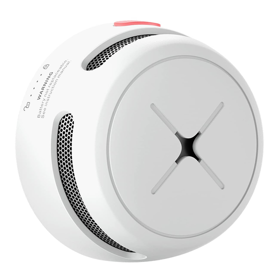
AEGISLINK
Wireless Interlinked Smoke Alarm
Model: S-RF500
User Manual
This user manual contains important information regarding the operation of your AEGISLINK smoke
alarm. Ensure you read this user manual fully before installing and operating the alarm. If you are installing
this smoke alarm for use by others, you must leave this manual (or a copy of it) with the end user.
Introduction
Thank you for purchasing our smoke alarm. This smoke alarm
conforms with the European Standard EN
14604:2005+AC:
2008and is designed to detect smoke. Our product lineups are constantly expanding.
Product Profile
Advertisement
Table of Contents

Related Manuals for Aegislink S-RF500

Summary of Contents for Aegislink S-RF500
- Page 1 Model: S-RF500 User Manual This user manual contains important information regarding the operation of your AEGISLINK smoke alarm. Ensure you read this user manual fully before installing and operating the alarm. If you are installing this smoke alarm for use by others, you must leave this manual (or a copy of it) with the end user.
-
Page 2: Package Contents
S-RF500 Buzzer Test/Silence Button LED Indicator Pinhole Pairing Button Package Contents 1 × Alarm Unit 1 × Mounting Bracket 2 × Screws 2 × Anchor Plugs 1 × User Manual 1 × Pin... -
Page 3: Safety Information
Safety Information IMPORTANT! DANGERS, WARNINGS, AND CAUTIONS ALERT YOU TO IMPORTANT OPERATING INSTRUCTIONS OR TO POTENTIALLY HAZARDOUS SITUATIONS. PAY SPECIAL ATTENTION TO THESE SITUATIONS. THIS ALARM IS NOT INTENDED TO ALERT HEARING IMPAIRED INDIVIDUALS. THE USE OF ALCOHOL OR DRUGS MAY ALSO IMPAIR ONE’S ABILITY TO HEAR THE SMOKE ALARM. - Page 4 The wireless interlinked alarms in one multi-pack have already been interconnected to each other, so the alarms in each multi-pack have their own independent interlinked network. If you have more than one multi-pack, you will need to connect them all to the same network, but you do not have to disconnect each alarm individually.
- Page 5 NOTES 1. The alarm will enter the searching mode or the pairing mode for 60 seconds with the LED flashing red. After 60 seconds, repeat step 2 to connect the alarms. If needed, press the pinhole pairing button once while the alarm is in the searching mode or the pairing mode, and the LED will stop flashing red and the alarm will quit the pairing mode to enter normal status.
-
Page 6: Alarm Test
In addition to the weekly tests you should perform, it is recommended to test the alarm after returning from a long trip or vacation. X-SENSE S-RF500 If your is interconnected to other wireless alarms, we recommend that every individual alarm is tested during the weekly test. -
Page 7: Installation Positioning
Installation Positioning NOTE: If a smoke alarm is installed in a kitchen, ensure it has an accessible silence button, and install it as far away from the stove and sink as possible to avoid false alarms. ①Study ②Bedroom ③Garage ④Living Room ⑤Kitchen ⑥Basement ⑦Smoke Detectors... - Page 8 5. If an alarm is installed onto a wall, a distance of 4-12 inches (10-30 cm) should be kept below the ceiling. 6. If the length of a room or hall is beyond 30 feet (900 cm), several alarms should be installed in the same room.
- Page 9 8. In multi-level houses or apartments, install at least one wireless smoke alarm on each level and keep them installed in a straight vertical line (see diagram) with as few obstacles between each of the interconnected alarms as possible to ensure optimal signal transmission. Locations to Avoid: 1.
-
Page 10: Installation Method
4. BATTERIES SHOULD NOT BE EXPOSED TO EXCESSIVE HEAT SUCH AS DIRECT SUNLIGHT, FIRE, ETC. Installation Method NOTE: Before installation, it is recommended to test the interconnected alarms in the rooms where you intend to install them to ensure that they are within transmission range and that nothing will interfere with their communication. - Page 11 counterclockwise. 2. Pull the battery removal tab to remove the battery, and then install a new battery, matching the correct polarity markings. 3. Test the alarm, and then mount the alarm onto the mounting bracket by twisting clockwise to lock the alarm.
-
Page 12: Alarm Mode
Alarm cancellation: When the smoke concentration level Unit that detects drops below alarm The LED flashes green once smoke None. threshold, the alarm signal every second for 5 seconds. initiates an alarm. will stop. Then, the alarm goes back to the standby mode. -
Page 13: Silence Mode
2. If the Initiating Unit Is Triggered by CO: When one CO alarm is triggered in the interconnected network, the unit will beep 4 times every 5.8 seconds, paired with the LED flashing red. Any other interlinked units in the network will follow suit—they will beep 4 times every 5.8 seconds, paired with the LED that flashes red 4 times first, followed by the LED that flashes green once with every beep. -
Page 14: Maintenance
Battery Life 5 years Sensor Type Photoelectric Safety Standard EN 14604:2005+AC:2008 Operating Ambient 40–100°F (4.4–37.8℃) Temperature ≤ 85% (non-condensing) Operating Relative Humidity ≥ 85 dB at 10 ft (3 m) @ 3.2 ± 0.3 kHz pulsing alarm Alarm Loudness Silence Duration About 9 minutes Operating Frequency 915.675MHz... -
Page 15: Troubleshooting
3. Never use detergents or other solvents to clean the unit. 4. Avoid spraying air fresheners, hair spray or other aerosols near the alarm. 5. Do not paint the unit. Paint will seal the vents and interfere with the sensor’s ability to detect fire. 6. -
Page 16: Environmental Protection
Waste electrical products should not be disposed of with household waste. Please recycle where facilities exist. Check with Local Authority or retailer for recycling advice. Manufacturer and Service Information Smartie International LLC Address: 160 Greentree Dr, Dover, DE 19904, USA Email: support@aegislink.co.uk...
Need help?
Do you have a question about the S-RF500 and is the answer not in the manual?
Questions and answers
How far away from a bedroom door can the S-RF500 be installed?